1
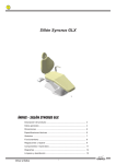
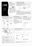
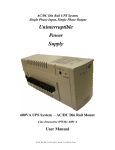
For your records
User Guide
The serial number of your UPS is on the rear panel. You
should note the serial number in the space provided below.
Retain this booklet as a permanent record of your
purchase to aid in identification in the event of theft or
loss.
Model No:
Serial No.:
Purchase Date:
Clever Series
Model CS385B, CS530B, CS730B
LIMITED WARRANTY
What the warranty covers:
Limitation of implied warranties:
THERE ARE NO WARRANTIES, EXPRESS OR IMPLIED, WHICH
EXTEND BEYOND THE DESCRIPTION CONTAINED HEREIN
We warrant this product to be free from defects in material and
INCLUDING THE IMPLIED WARRANTY OF MERCHANTABILITY AND
workmanship during the warranty period. If a product proves to be
FITNESS FOR A PARTICULAR PURPOSE.
defective in material or workmanship during the warranty period, we will at
our sole option repair or replace the product with a like product.
How long the warranty is effective:
For accurate warranty period and conditions, please contact local branch offices or
your dealers.
Exclusion of damages:
OUR LIABILITY IS LIMITED TO THE COST OF REPAIR OR
REPLACEMENT OF THE PRODUCT. WE SHALL NOT BE LIABLE FOR:
1.
DAMAGE TO OTHER PROPERTY CAUSED BY ANY DEFECTS IN THE
PRODUCT*, DAMAGES BASED UPON INCONVENIENCE, LOSS OF
Who the warranty protects:
USE OF THE PRODUCT, LOSS OF TIME, LOSS OF PROFITS, LOSS OF
This warranty is valid only for the first consumer purchaser.
BUSINESS OPPORTUNITY, LOSS OF GOODWILL, LOSS OF DATA,
LOSS OF SOFTWARE, COSTS OF SUBSTITUTE EQUIPMENT,
What the warranty does not cover:
INTERFERENCE WITH BUSINESS RELATIONSHIPS, CLAIMS BY THIRD
1.
2.
3.
Any product on which the serial number has been defaced, modified or
removed.
Damage, deterioration or malfunction resulting from:
a) Accident, misuse, neglect, fire, water, or other acts of nature,
unauthorized product modification, or failure to follow instructions
supplied with the product.
b) Repair or attempted repair by anyone not authorized by OPTI.
c) The fault is the result of accidental damage or damage in transit or
transportation, including but not limited to liquid spillage.
d) Removal or installation of the product.
e) Causes external to the product.
f) Use of supplies or parts not meeting our specifications.
g) Normal wear and tear.
h) Any other cause which does not relate to a product defect.
Removal, installation and set-up service charges.
PARTIES, OR OTHER COMMERCIAL LOSS, EVEN IF ADVISED OF THE
POSSIBILITY OF SUCH DAMAGES.
2.
ANY OTHER DAMAGES, WHETHER INCIDENTAL, CONSEQUENTIAL
OR OTHERWISE.
3.
ANY CLAIM AGAINST THE CUSTOMER BY ANY OTHER PARTY.
Effect of state law (for US):
This warranty gives you specific legal rights, and you may also have other
rights which vary from state to state. Some states do not allow limitations on
implied warranties and/or do not allow the exclusion of incidental or
consequential damages, so the above limitations and exclusions may not
apply to you.
Life Support:
We do not recommend the use of our UPS products for life support
IMPORTANT SAFETY INSTRUCTIONS
IMPORTANT SAFETY INSTRUCTIONS
SAVE THESE INSTRUCTIONS
equipment or direct care where failure of a UPS product could cause failure
of, or diminished effectiveness of the life support equipment or patient care.
*Except as expressly provided for by the UPS “Equipment Protection Policy”
●
EFFECTIVE October 1, 1997
●
●
●
●
●
●
●
●
WARNING (SAVE THESE INSTRUCTIONS): This manual contains
important instructions that should be followed during installation and
maintenance of the UPS and batteries.
WARNING (Controlled Environment): These units are intended for
installation in a temperature controlled, indoor area free of conductive
environment.
CAUTION: Risk of electric shock, do not remove cover. No user
serviceable parts inside. Refer servicing to qualified service personnel.
CAUTION: Do not dispose of batteries in a fire, the battery may explode.
CAUTION: Do not open or mutilate the battery, released electrolyte is
harmful to the skin and eyes. It may be toxic.
CAUTION: A battery can present a risk of electric shock and high short
circuit current. The following precaution should be observed when working on
batteries:
Remove watches, rings or other metal objects.
Use tools with insulated handles.
Wear rubber gloves and boots.
Do not lay tools or metal parts on top of batteries.
Disconnect charging source prior to connecting or disconnecting battery
terminals.
Servicing of batteries should be performed or supervised by personnel
knowledgeable of batteries and the required precautions. Keep unauthorized
personnel away from batteries.
When replacing battery, replace with same type.
Do not connect any additional batteries by yourself.
-1-
1.1 “Power On” Indicator
TABLE OF CONTENTS
Important Safety Instructions ................................................................................... 1
1. Presentation .......................................................................................................... 2
Power On indicator illuminates when utilities’ power is normal. The indicator also
illuminates per each 4 seconds under Backup mode. Rapid flash (1 sec) means the inner
battery should be replaced again.
Attention: The internal battery has to be replaced when rapid flash occurred under AC
mode.
2. Installation............................................................................................................ 3
3. Operation.............................................................................................................. 4
4. Software and Computer Interface (Option) .......................................................... 5
5. Battery Maintenance and Replacement ................................................................ 6
Appendix A Troubleshooting.................................................................................... 6
Appendix B Specifications ....................................................................................... 7
1.2 Outlets Design for AC Adapters
Allow two AC power adapter blocks to be plugged into the UPS without blocking adjacent
outlets.
1.3 Battery Power-Supplied Outlets
Please read and save this manual!
Thank you for selecting this uninterruptible power system (UPS). It provides you with a
perfect protection for connected equipment. The manual is a guide to install and use the
UPS. It includes important safety instructions for operation and correct installation of the
UPS. If you should have any problems with the UPS, please refer to this manual before
calling customer service.
Inspect the UPS upon receipt. The packaging is recyclable; keep it for reuse or disposed
of properly.
Provide instantaneous back-up power and full-time bypass protection to your equipment.
Ensure temporary uninterrupted operation of your equipment during power failure.
1.4 Full-time Bypass Protection Outlets
Provide full-time Bypass protection to your equipment. Prevent surge from traveling
through your system through unprotected peripherals.
1.5 Power button (ON/OFF/TEST/SILENCE)
The UPS can be turned on while pressing power button until buzzer stops (about 2
seconds). After the UPS is turned on, it conducts a self-test and enter normal mode.
Press the power button for 1 second under normal mode would also enable the self-test
function again. The silence function can be enabled/disabled by pressing the power
button for 1 second under backup mode.
In addition, Power button can be used as the master on/off switch of your equipment by
leaving your equipment connected to UPS and switched on. To turn off the UPS, please
press power button until buzzer stops (about 2 seconds).
1. PRESENTATION
Front View and Side View
1.6 Circuit Breaker (or Fuse)
Serves as an overload and fault protection. This is a critical component of the advanced
UPS surge protection circuit.
Circuit Breaker
Circuit Breaker
Switch
Switch
2. INSTALLATION
2.1 Recharge the battery
385 VA
530/730 VA
The styles of cover are just for reference only
-2-
UPS may be used by anyone immediately upon receipt. The battery is fully charged
before shipped from the factory. However, user is recommended to recharge the battery
at least four hours before using UPS. Energy loss may occur during shipping or long
duration storage. To recharge the battery, simply let UPS be plugged into an AC outlet
and switch it on.
2.2 Connect the loads
Plug your primary equipment (e.g. computer, monitor and critical data storage device,
-3-
etc.) to the Battery backup outlets. Plug your peripheral equipment (e.g. printer, scanner,
fax, or audio device) to the Full-time Bypass Protection outlets. Do not plug laser printer
to the UPS, as its power demand is much higher than typical peripherals and may cause
the circuit breaker (or fuse) to trip.
3.2 Check the power requirement of your equipment
If you wish to protect a fax or a modem, connect the telephone cable from the wall outlet
to the “IN” jack. Connect the telephone cable (provided) from the “OUT” jack to the fax or
modem. To protect a10/100Base-T (UTP) network interface, obtain and use a UTP cable
to connect the “OUT” jack to your computer.
3.2.1. Make sure the total power of your equipment does not exceed rating capacity.
3.2.2. Also make sure the equipment you plugged into the Battery Power-Supplied
outlets does not require total power exceeding the capacity of the UPS. Otherwise,
overload may occur and cause the circuit breaker to trip. If the power requirement of your
equipment differs from VA, convert the requirement power into VA by doing the
calculations below:
3.2.3. If the power requirement of your equipment is listed other than VA, convert the
requirement into VA by doing the calculations below.
Watt (W) X 2 =
VA
2.4 Connect to the utility power
3.3 Limited rating power of UPS
Plug UPS to a 2-pole, 3-wire grounding receptacle. Make sure the battery supply outlets
of the UPS do not service equipment requiring heavy electricity (e.g. refrigerator, air
conditioner, copier, etc.)
Attention: When using extension cords, make sure the total rating of the loads is
suitable.
When utility power failure occurs, the battery power outlets will supply power to your
equipment from its battery. The buzzer will beep once every 4 seconds. Be sure that your
equipment is running under the limited rating power. To restore the battery power by
plugging UPS back in to the existing power source. Perform the self-test to make sure
UPS works properly.
2.3 Connect the telephone
3.4 Checking table for Buzzer, LED and Status.
2.5 UPS self-test
UPS will conduct a self-test once switched on it each time. Besides this, switch on your
equipment after switch on UPS. This function is disabled while buzzer is alarmed caused
by full (over) loads.
Buzzer
OFF
OFF
2.6 Battery auto-charging
The internal battery would be charged by charging circuit automatically, while utility
power is connected to the unit.
2.7 Auto restart feature
UPS would shut-down while battery voltage is too low, and wake up automatically when
utility power and battery voltage is normal.
2.8 Overload protection
UPS automatic shut down if load exceeds 110% of nominal rating for 10 sec or if load
exceeds 120% of nominal rating for 3 sec.
2.9 Optimal battery status
ON
ON:4’S
OFF:1’S
ON:1’S
OFF:4’S
ON:1’S
OFF:1’S
ON:0.5’S
OFF:0.5’S
Power-on LED (GREEN)
ON
ON:0.5’S
OFF:0.5’S
AC MODE ON
BACKUP MODE
ON:1’S
OFF:4’S
AC MODE ON
BACKUP MODE
ON:1’S
OFF:4’S
ON:1’S
OFF:4’S
ON:1’S
OFF:1’S
ON
Status
AC MODE
BATTERY FAULT
OVER LOAD
FULL LOAD
BACKUP
MODE
BATTERY
LOW
CHARGER ABNORMAL
To maintain the optimal battery status, leave UPS plugged in and switched on at all time.
4. SOFTWARE AND COMPUTER INTERFACE
2.10 No load Shutdown feature
UPS is equipped with no load shutdown function. While no loads are connected to the
UPS, the unit will automatically shutdown after 3 minutes.
3. OPERATION
3.1 Simple test
It is recommended that the user perform a simulation test when using UPS for the first
time or when adding an additional piece of equipment. Conduct a simulation-test: first,
switch on UPS and wait for the power indicator to light up, then simply unplug UPS to
simulate the event of utility failure.
-4-
4.1 Power Monitoring Software
The OPTI-SAFE Sentinel software (or other power monitoring software) is applied
standard USB interface to perform monitoring functions, and then provides an orderly
shutdown of a computer in the event of power failure. Moreover, OPTI-SAFE Sentinel
displays all the diagnostic symptoms on monitor, such as Voltage, Frequency, Battery
level and so on. The software is available for Windows 95/98/2000/Me, Windows NT V4.0
or later, Novell Netware and others. Call your dealer for more information on computer
OS compatible solutions.
-5-
4.2 Interface Kits
A series of interface kits is available for operation systems that provide UPS monitoring.
Each interface kit includes the special interface cable required to convert status signals
from the UPS into signals which individual operating system recognize. The interface
cable at UPS side must be connected to REMOTE PORT, at computer side can be either
COM 1 or COM 2. The other installation instructions and powerful features please refer to
READ.ME file.
APPENDIX B SPECIFICATIONS
MODEL
UPS Capacity(VA/W)
No. of sockets
(NEMA 5-15R)
CAUTION: Use only factory supplied or authorized UPS monitoring cable!
4.3 The characteristics of computer interface port
The computer interface port has the following characteristics:
The communication port on the back of the UPS may be connected to host computer.
This port allows the computer to monitor the status of the UPS and control the operation
of the UPS in some cases. Its major functions normally include some or all of the
following:
To broadcast a warning when power fails.
To close any open file before the battery is exhausted.
To turn-off the UPS.
Some computers are equipped with a special connector to link with the communication
port. In addition, special plug-in cord may be needed. Some computers may need special
UPS monitoring software. Contact your dealer for the details on the various interface Kits.
Output
Voltage (on battery)
730VA/365W
2 Battery
2 Battery Backup +
Backup
2 Surge Protection
Simulated sine wave at 100V/115V/ 220V/
240V +/-5% AVR Controlled by PWM
Protection
Frequency
50 or 60Hz +/- 10% (auto sensing)
Unit Input
Circuit breaker for overload & short circuit protection
Overload Protection
Type
Battery
50 or 60Hz +/- 0.3Hz
100V +/-20%, 110V +/- 25%,
220V/230V/240V, 170V~280 at line input
UPS automatic shutdown if overload exceeds 110%
of nominal at 10 seconds, 120% at 3 seconds
UPS output cut off immediately
460 Joules(MAX.), 2ms
Sealed, maintenance-free lead acid batteries with 3-5
years typical lifetime
Typical Recharge Time
(to 90% of full capacity)
To store UPS, cover it and store it with the battery fully charged. During extended storage, just
connect the utility power to recharge the battery every three months to ensure battery life.
Protection
APPENDIX A TROUBLESHOOTING
Weight (Net)
-6-
530VA/265W
Voltage (single phase)
Input
Spike Protection
Possible Cause
Solution
Circuit breaker button popped up as Unplug at least one piece of equipment
a result of overload.
from the Full-time Surge Protection
outlets.
Switch off UPS, wait 5 seconds, reset the
circuit breaker (press down breaker
button), then switch on UPS.
UPS doesn’t
Battery undercharged or depleted
Recharge the battery by leaving the UPS
perform to its
due to frequent power outages.
plugged in and switched on.
expected runtime. The power required by your
Unplug at least one piece of equipment
from the UPS outlets.
equipment slightly exceeds the
capacity of the UPS.
The battery is slightly worn-out.
Consider replacing the battery.
UPS cannot be
The battery is worn-out.
Replace the battery the instructions in this
turned on.
manual.
Mechanical problem.
Contact your sales representative.
385VA/190W
<10 milliseconds, including detection time
5.1 Battery maintenance
Problems
Full-time Bypass
Protection outlets
stop providing
power to the
equipment
CS730B
Transfer Time
Short Circuit
5.2 Storage
CS530B
Frequency (on battery)
5. BATTERY MAINTENANCE
For the preventive maintenance, keep the area around the UPS clean and duty-free.
Please also keep the UPS at ambient temperature of 25℃ (77℉). It is recommend that
the batteries charge for 24 hours after long storage.
CS385B
Physical
6 hours
Automatic itself-test, Over discharge protection, short
circuit protection by fuse
3.53 lbs
5.73 lbs
1.6 kgs
2.6 kgs
3.74×3.74×6.22
Dimensions (L×W×H)
inches
95×95×158 mm
Interface
Communication Port
Battery Back-Up
Alarm
3.74 × 5.43 × 6.22 inches
95 × 138 ×158 mm
USB port
Slow beeping sound every 4 seconds (Buzzer can be
muted by pressing main switch button)
Battery Low
Continue beeping sound every second
100% load
Continue beeping sound every 4 second
Overload
Continue beeping sound
Ambient operation
Environment
3,500 meters max. elevation, 0-95% humidity
(non-condensing water), 0-40℃
Audible Noise
<40dBA (1 meter from surface)
-7-