1
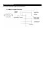
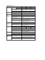
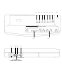
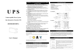
OFFICE UPS
MULTI-DEVICE PROTECTION UPS
500S/600S/750S
USER’S MANUAL
1.Safety instructions
Thank you for selecting this uninterrupted power source. It provides you with
better protection for connected equipment.
Please read this manual!
This manual provides safety, installation and operating instructions that will help
you derive the fullest performance and service life that the UPS has to offer.
Please save this manual!
It includes important instructions for the safe use of this UPS and for quick
solutions factory service should take as the UPS comes into question.
Please save or recycle the packaging materials!
The UPS’s shipping materials were designed with great care to provide
protection from transportation related damage. These materials are invaluable
if you ever have to return the UPS for service. Damage created during delivery
is not covered under the warranty.
2.CAUTION!
• Caution: Risk of electric shock hazardous live parts inside this unit are
energized from the battery supply even when the input AC power is
connected.
• Warning: To reduce the risk of fire, replace only with the same type and
rating of fuse.
• Warning: To reduce the risk of fire or electric shock, install in
temperature and humidity controlled indoor area of conductive
contaminants.
• CAUTION: OFFICE UPS has an internal battery source. When the
On/Off control is on, the Battery Power output outlets are energized,
even when the unit is not plugged in.
• Warning: Place OFFICE UPS indoors, in a protected area that has
adequate air flow, and is free from excessive dust. Do not place OFFICE
UPS to be exposed in envirmonment of humidity, rain, heatemitting
source, or directs sunlight.
• Warning: Connect OFFICE UPS to a two-pole, three-wire, grounded AC
power outlet. The outlet must be protected by appropriate branch
protection(fuse or circuit breaker).
• Warning: Connection to any other type of outlet may result in a shock
hazard and riolate local electrical codes.
• Warning: To reenergize OFFICE UPS in an emergency, first switch the
On/Off control to the off position. Then, unplug OFFICE UPS office from
the wall outlet. To debilitate the unit entirely, disconnect the battery. (See
“Battery Replacement” below.)
• Warning: Use of OFFICE UPS in an life support applications where
failure of this equipment can reasonably be expected to cause the
failure of the life support equipment or to significantly affect its safety or
effectiveness is not recommended.
• CAUTION: Risk of Electrical Shock! Battery circuit is not isolated from
AC input. Hazardous voltage may exist between terminal and ground.
Disconnect power cord from wall receptacle before servicing battery.
• CAUTION: Telephone line current limiting feature (where applicable)
could be rendered inoperable if improperly installed. Never install
telephone wiring during an electrical storm.
3.Installation
3.1Note: When delivered and stored, the battery in OFFICE UPS will more or
less lose charge. Full recharge will be achieved after about 4 hours of normal
operation. Do not expect full battery run time during this initial recharge period.
3.2Plug OFFICE UPS into an activating outlet. Do not plug it into a service
branch that has a heavy motor load equipped with it (e.g., an air conditioner or
refrigerator.) Operate in accordance with the indications below prior to switching
OFFICE UPS on.
3.3Plug your computer and monitor into the Battery Power output outlets.
Positions of the rest outlets provide for and datacritical device that requires
power under condition of utility power failure (e.g., an external tape backup,
storage drive or CD ROM.)
Caution: Never connect a laser printer with the Battery Power output
outlets.
3.4Plug your system peripheral equipment (e.g., a scanner, fax printer, audio
device or generator ) into the Surge Protection outlets. There is no power
supplied with these outlets in the event of utility power failure.
3.5The RJ45/RJ11 modular sockets are at the back of OFFICE UPS (300/500VA
Models only), offering protection against surges brought to your computer’s
fax/modem or network interface card by the telephone or network wiring. To
protect a fax/modem, connect the existing cable from the wall outlet to the “IN”
jack. Connect the telephone cable that was supplied with OFFICE UPS from the
“OUT” jack, to the fax/modem. To protect a 10Base TUPT network interface,
contact your LAN manager for a short length of UTP cable with which the
connection between the “OUT” jack and your computer can be made.
3.6Connect Computer interface: UPSMON series software (or other software
supporting RS232 communication) and an interface kits can be used with this
UPS. Use only kits supplied or approved by the manufacturer. If used, connect
the interface cable to the 9pin computer interface port to OFFICE UPS.
Note: Computer interface connection is optional. The UPS works properly
without a computer interface connection.
Caution: Use only factory supplied or authorized UPS monitoring cable.
3.7Switch On/Off control of all system equipment to the on position.
3.8Turn on OFFICE UPS, and all the outlets will be powered. UPS will also
perform a self-test function for 8 seconds, which resolves if the battery power is
sufficient for connected loads. Always keep OFFICE UPS in “On” condition to
keep optimal battery charge.
Note: Classify the instruction above as reference while battery has
thoroughly worn out to be replaced.(3-6 years)
4.Description and Operation
4.1Battery Power Outlets
The four Battery Power output outlets will provide protection if under status of
surge or battery backup. Plug your computer, monitor, and other “datacritical”
device into these outlets. There is still appropriate space for an adapter block in
the outlet configuration.
Caution: Never plug a laser printer into the Battery Power output outlets.
4.2 Surge Protected Outlets
The four outlets can offer protection against surge such as those caused by
connected equipment that has high initial current or lightning. In the event of
utility power failure, plug equipment that consumes no power into these outlets.
Devices included could be a printer, scanner, fax, power generator or an audio
device.
4.3 On/Test button
This button controls the power to all the outlets. For maintenance of battery
optimum charge, always leave OFFICE UPS in “On” condition.
4.4 Line OK Indicator (GREEN LED)
A green indicator is on when the OFFICE UPS is switched on and is supplying
conditioned utility power to the outlets. When first switched on, OFFICE UPS will
perform selftest for 8 seconds. During the period of test, the battery can be
examined if it affords to provide the equipment that is connected to the Battery
Power Supplied outlets. Selftest succeeds when following this procedure:
(1) The On/Off indicator displays four seconds illumination while OFFICE UPS is
checking the battery charger.
(2) When OFFICE UPS examines the battery, the Backup indicator lights for four
seconds.
(3) Selftest is completely finished when the On/Off indicator illuminates again.
4.5 CHARGING indicator (YELLOW LED)
The LED illuminates when the battery is charged by line input power. It always
lights once the mains is existing.
Accompanying Audible Alarm
If the battery energy detected by OFFICE UPS runs low, the UPS will sound an
audible alarm for 30 seconds to caution that its duration may be shorter than
anticipated. A minimum of four hours for OFFICE UPS recharge is allowed. The
audible alarm could also indicate an overload condition. When the UPS is
overloaded, remove noncritical loaded equipment from Battery Power output
outlets.
4.6 BACK UP indicator (YELLOW LED )
The LED illuminated when the UPS is supplying battery power to the loads.
Accompanying Audible Alarm
As soon as the utility power fails, the OFFICE UPS will sound an audile alarm.
When the battery runs low to about 2 minutes of duration, the alarm will emit
continuous beeps. This warns you that your run time is approximately exhausted,
and you in no time have to save your files and shut down your system!
4.7 OVERLOAD indicator (RED LED)
The LED lights up when the loads connected to the UPS exceed the UPS’s
capacity.
4.8 BATTERY FAULT indicator (RED LED)
The LED is on when the UPS’s battery is no longer useful and must be replaced.
Note: When replacing battery, disconnect the utility power, and then open the
case. The battery’s polarity should be carefully observed while installing the new
battery to avoid short.
4.9 Electrical Wiring Fault Indicator
This indicator lights when there is either no ground circuit or a reversed polarity
in the building wiring. If it lights, ask full support from qualified service personnel
to check your building wiring.
4.10 Circuit Breaker
This circuit breaker will trip to disconnect the unit from utility power if OFFICE
UPS is in an extremely overloaded condition. When this happens, the black
button will pop up, and the Surge Protection outlets will stop powering. If this
occurs, unplug at least one piece of equipment. Also press circuit breaker button
back into place to reset the circuit breaker.
4.11 AC INPUT POWER RECEPTACLE
4.12 Modem/Fax/10BaseT”IN” Jack
OFFICE UPS provides protection from surges working on modem, fax or
10BaseT wiring. Connect the existing, incoming wiring from the wall, into this
jack.
4.13 Modem/Fax/10BaseT”OUT” Jack
Connect the telephone that was provided with OFFICE UPS from this jack to
your computer for modem or fax application. For 10BaseT applications, please
contact your LAN manager for a short length of UTP cable to get connection
from this jack to your computer.
4.14 COMPUTER INNTERFACE
5.Wall Mounting
5.1 It is acceptable for vertical or horizontal positioning of OFFICE UPS to a wall
surface. Use the template above to place the securing fasteners (not supplied).
Note: Place the On/Off control to the right for horizontal positioning, to the top for
vertical.
5.2 Hold this page against the wall with the appropriate edge parallel to the floor.
5.3 Use thumbtacks to hold this page in place. Be sure that the template circles
line up where you want the mounting fasteners to be installed. Use sharp nail or
pin to penetrate the center each appropriate template circle to mark the wall.
5.4 Install fasteners at the marked locations. Leave the head of both fasteners
5/16"(8mm) out from the surface of the wall. Fasteners must be able to reliably
support 15lb (6.8kg).
5.5 Put OFFICE UPS in position of the keyhole slots over the fastener heads.
For vertical mounting, slide the unit down into place. For horizontal mounting,
turn it slightly counterclockwise until it is securely in place.
6.Battery Replacement
6.1 CAUTION: Read and follow safety precautions indicated before replacing
battery. Serving and precautions of battery should be performed or supervised
by qualified service personnel to ensure correct operation. Keep unauthorized
persons away from batteries.
6.2 CAUTION: When replacing, use the same number and type of sealed, lead
acid battery. Use of any other batteries may present a risk of fire or explosion.
Ask your dealer for further information to ensure ease of batteries replacement.
The battery is recyclable; save it for reuse or dispose of it in proper way.
6.3 CAUTION: The battery can cause a risk of electrical shock and high
shortcircuit current. Make sure to observe the following precautions as working
with batteries for disposal or replacement; remove watches, rings, and other
metal objects; use tools that have insulated handles; do not dispose of battery in
a fire, it may explode; do not open or willfully damage the battery, since released
electrolyte is harmful to the skin and eyes, and may be toxic.
6.4 Switch all equipment On/Off controls to the off position, and unplug from
OFFICE UPS. Turn off OFFICE UPS, and unplug it from the wall outlet to ensure
its off condition.
6.5 Place the OFFICE UPS face down on soft material. Loose the screw holding
the top of the unit to the bottom. After it is released, use both thumbs to push
battery cover tabs in and away from unit.
6.6 Once removing battery cover, pull back the battery retaining clip, and then tip
the battery up and out.
6.7 Disconnect the battery wires one at a time. Grasp each wire connector and
pull straight back. Be careful not to pull the wires, Take out spent battery at the
end of its useful life and return it to the factory for recycling.
6.8 Place the new battery into the battery compartment. Connect the red wire to
the plus (+) pole; black wire to the minus (). Tip the new battery, pole end first,
into the battery compartment. Lightly press the battery until the retaining clip
snaps into place.
6.9 Place back the battery cover. We recommend that new battery be initially
charged for at least 4 hours to help condition the battery.
7.Software Options
7.1 The UPSMON software: The UPSMON software is applied standard RS232
interface to perform monitoring functions, and then provides an orderly shutdown
of a computer in the event of power failure. Moreover, UPSMON displays all the
diagnostic symptoms on monitor, such as Voltage, Frequency, Battery level and
so on. The software is available for DOS, Windows 3.1x, Window 95 Window 98
& NT V3.5 or later.
7.2 Interface Kits: A series of interface kits is available for operation systems that
provide UPS monitoring. Each interface kit includes the special interface cable
required to convert status signals from the UPS into signals that individual
operating system recognize. The interface cable at UPS side must be connected
to REMOTE PORT, at computer side can be either COM1 orCOM2. The other
installation instructions and powerful features please refer to READ.ME file.
Caution: Use only factory supplied or authorized UPS monitoring cable.
8.Computer Interface Port
The computer interface port has the following characteristics:
D-SUB 9 Pin Female Connector
Low Battery
Contacts
Normally
Open
Mains Failure
Common
UPS Shut Down or
RS232 TD Pin3
Signal High Min. 1 Second
RS232 RD Pin2
RS232RTS Pin 7
RS232DTR Pin4
No Connection
Pin Number
SPECIFCATION
MODEL
OUTPUT
KOF-500S
Capacity
KOF-600S
KOF-750S
(on battery)
500VA
600VA
750VA
(surge rotection) 500VA
400VA
250VA
Voltage (on battery)
Simulated sine wave at 100/115/220/240
±5%
Frequency (on battery)
50 or 60HZ±0.5%
Transfer Time
2/4 milliseconds, including detection time
INPUT
Voltage
±15% at line input
Frequency
50 or 60HZ ±10 (auto sensing)
PROTECTION Spike Protection
240 Joules, 2ms
AND
EMI/RFI Filter
10dB at 0.15MHz, 50dB at 30MHz
FILTERING
Overload Protection UPS
If overload exceeds 105% of normal at 20
automatic shutdown
seconds
UPS Output
Overload & short circuit protection
Tel/Fax/Modem 10 Base-T Cable Single line (2 wires, RJ11) or network (UPT,
Port
11/RJ45) compatible jacks
Short Circuit
UPS output cut off immediately or input
circuit breaker protection
User
Type
Sealed, Maintenance-free lead acid
Replaceable Typical Recharge Time
4 hours (to 90% of full capacity)
BATTERY
Protection
Automatic self-test & discharge protection,
replace battery indicator
Back-up Time ( minutes )
7-15
15-30
18-33
PHYSICAL
Net Weight (Kg)
3.7
4.0
4.2
Shipping Weight (Kg)
4.0
4.3
4.5
Dimension (mm) WxDxH
420x170x65
Input Inlet
IEC320 power inlet
Receptacles
NEMA 5-15R (115V)/IEC 320 female
appliance coupler (230V)
ALARM
Battery Back-up
Slow beeping sound (about 0.47Hz)
Battery Low
Rapid beeping sound (about 1.824Hz)
Overload
Continue beeping sound
INTERFACE RS232 INTERFACE
Bi-directional communication port
ENVIRONAmbient Operation
3500 meters max. elevation, 0-95%
MENT
humidity noncondensing, 0-40 deg C
Audible noise
<40dBA (1 meter from surface)
Storage Condition
15000meters max. elevation
4.9
4.8
4.7
4.6
4.5
4.4
Surge Protection
Battery Power Output
4.1
4.11
AC INPUT
4.12 4.13
4.14
REMOTE PORT
TEL/FAX/MODEM
SURGE PRTECTION PORT
4.2
4.3
4.10