1
Chapter.book : covbook
1 Tue Sep 17 12:21:10 1996
Xilinx ABEL
User Guide
Introduction
State Machine Design
Methodology
ABEL-HDL for FPGAs
Getting Started
How to Use Xilinx ABEL
Commands
XEPLD
JEDEC and PALASM Files
Design Examples
Glossary
Error and Warning Messages
Supported Device Types
Xilinx ABEL User Guide — 0401317 01
Printed in U.S.A.
Chapter.book : covbook
2 Tue Sep 17 12:21:10 1996
Xilinx ABEL User Guide
R
, XACT, XC2064, XC3090, XC4005, and XC-DS501 are registered trademarks of Xilinx. All XC-prefix
product designations, XACT-Floorplanner, XACT-Performance, XAPP, XAM, X-BLOX, X-BLOX plus, XChecker,
XDM, XDS, XEPLD, XPP, XSI, BITA, Configurable Logic Cell, CLC, Dual Block, FastCLK, HardWire, LCA, Logic
Cell, LogicProfessor, MicroVia, PLUSASM, SMARTswitch, UIM, VectorMaze, VersaBlock, VersaRing, and ZERO+
are trademarks of Xilinx. The Programmable Logic Company and The Programmable Gate Array Company are
service marks of Xilinx.
IBM is a registered trademark and PC/AT, PC/XT, PS/2 and Micro Channel are trademarks of International Business
Machines Corporation. DASH, Data I/O and FutureNet are registered trademarks and ABEL, ABEL-HDL and ABELPLA are trademarks of Data I/O Corporation. SimuCad and Silos are registered trademarks and P-Silos and P/CSilos are trademarks of SimuCad Corporation. Microsoft is a registered trademark and MS-DOS is a trademark of
Microsoft Corporation. Centronics is a registered trademark of Centronics Data Computer Corporation. PAL and
PALASM are registered trademarks of Advanced Micro Devices, Inc. UNIX is a trademark of AT&T Technologies,
Inc. CUPL, PROLINK, and MAKEPRG are trademarks of Logical Devices, Inc. Apollo and AEGIS are registered
trademarks of Hewlett-Packard Corporation. Mentor and IDEA are registered trademarks and NETED, Design
Architect, QuickSim, QuickSim II, and EXPAND are trademarks of Mentor Graphics, Inc. Sun is a registered
trademark of Sun Microsystems, Inc. SCHEMA II+ and SCHEMA III are trademarks of Omation Corporation. OrCAD
is a registered trademark of OrCAD Systems Corporation. Viewlogic, Viewsim, and Viewdraw are registered
trademarks of Viewlogic Systems, Inc. CASE Technology is a trademark of CASE Technology, a division of the
Teradyne Electronic Design Automation Group. DECstation is a trademark of Digital Equipment Corporation.
Synopsys is a registered trademark of Synopsys, Inc. Verilog is a registered trademark of Cadence Design Systems,
Inc.
Xilinx does not assume any liability arising out of the application or use of any product described or shown herein;
nor does it convey any license under its patents, copyrights, or maskwork rights or any rights of others. Xilinx
reserves the right to make changes, at any time, in order to improve reliability, function or design and to supply
the best product possible. Xilinx will not assume responsibility for the use of any circuitry described herein other
than circuitry entirely embodied in its products. Xilinx devices and products are protected under one or more of
the following U.S. Patents: 4,642,487; 4,695,740; 4,706,216; 4,713,557; 4,746,822; 4,750,155; 4,758,985;
4,820,937; 4,821,233; 4,835,418; 4,853,626; 4,855,619; 4,855,669; 4,902,910; 4,940,909; 4,967,107; 5,012,135;
5,023,606; 5,028,821; 5,047,710; 5,068,603; 5,140,193; 5,148,390; 5,155,432; 5,166,858; 5,224,056; 5,243,238;
5,245,277; 5,267,187; 5,291,079; 5,295,090; 5,302,866; 5,319,252; 5,319,254; 5,321,704; 5,329,174; 5,329,181;
5,331,220; 5,331,226; 5,332,929; 5,337,255; 5,343,406; 5,349,248; 5,349,249; 5,349,250; 5,349,691; 5,357,153;
5,360,747; 5,361,229; 5,362,999; 5,365,125; 5,367,207; 5,386,154; 5,394,104; 5,399,924; 5,399,925; 5,410,189;
5,410,194; 5,414,377; RE 34,363, RE 34,444, and RE 34,808. Other U.S. and foreign patents pending. Xilinx, Inc.
does not represent that devices shown or products described herein are free from patent infringement or from any
other third party right. Xilinx assumes no obligation to correct any errors contained herein or to advise any user of
this text of any correction if such be made. Xilinx will not assume any liability for the accuracy or correctness of
any engineering or software support or assistance provided to a user.
Xilinx products are not intended for use in life support appliances, devices, or systems. Use of a Xilinx product in
such applications without the written consent of the appropriate Xilinx officer is prohibited.
Xilinx Development System
Chapter.book : covbook
3 Tue Sep 17 12:21:10 1996
Xilinx ABEL
User Guide
Xilinx ABEL User Guide
Accelerate FPGA Macros
with One-Hot Approach
Chapter.book : covbook
4 Tue Sep 17 12:21:10 1996
Xilinx ABEL User Guide
Xilinx Development System
Chapter.book : preface.doc
i Tue Sep 17 12:21:10 1996
Preface
About This Manual
This manual describes the Xilinx ABEL program, which you can use
to create Xilinx FPGA modules using state machines, Boolean
equations, and truth tables. You can also create Xilinx EPLD modules
and full designs.
Before using this manual, you should be familiar with the operations
that are common to all Xilinx’s software tools: how to bring up the
system, select a tool for use, specify operations, and manage design
data. These topics are covered in the Xilinx Reference Guide.
Other publications that you can consult for related information are
the Xilinx ABEL Software Design Reference Manual from Data I/O and
Xilinx’s Viewlogic Interface User Guide, OrCAD Interface User Guide,
and Mentor Version 8 Interface User Guide.
Manual Contents
This manual covers the following topics:
●
Chapter 1, ‘‘Introduction,” describes Xilinx ABEL’s prominent
features and the design flows and files used in FPGA and EPLD
design.
●
Chapter 2, ‘‘State Machine Design Methodology,” shows you how
to design a state machine and gives examples using Xilinx ABEL.
●
Chapter 3, ‘‘ABEL-HDL for FPGAs,” describes how to use the
ABEL Hardware Description Language (ABEL-HDLTM) for FPGA
designs.
Xilinx ABEL User Guide — 0401317 01
i
Chapter.book : preface.doc
ii Tue Sep 17 12:21:10 1996
Xilinx ABEL User Guide
ii
●
Chapter 4, ‘‘Getting Started,” describes the Xilinx ABEL
environment for PCs and workstations. It also explains how to
invoke and exit XABEL and how to obtain help.
●
Chapter 5, ‘‘How to Use Xilinx ABEL,” gives step-by-step
instructions for performing Xilinx ABEL’s major functions.
●
Chapter 6, ‘‘Commands,” lists and describes all the commands
available in XABEL: XDM commands on the PC and workstation,
and command-line commands for ABL2XNF, ABL2PLD, SynthX,
AHDL2X, BLIFOPTX, PLASimX, and ImproveX.
●
Chapter 7, ‘‘XEPLD,” describes how to use Xilinx ABEL to process
EPLD designs.
●
Chapter 8, ‘‘JEDEC and PALASM Files,” describes how to convert
JEDEC and PALASM files to ABEL-HDL format so that Xilinx
ABEL can process them.
●
Chapter 9, ‘‘Design Examples,” gives several extended examples
demonstrating how to use Xilinx ABEL to process FPGA and
EPLD designs.
●
Appendix A, “Glossary,” defines all the terms that you need to
understand to use Xilinx ABEL effectively.
●
Appendix B, ‘‘Error and Warning Messages,” lists the error and
warning messages that Xilinx ABEL issues.
●
Appendix C, ‘‘Supported Device Types,” lists the device types for
FPGAs and EPLDs that Xilinx ABEL supports.
●
Appendix D, ‘‘Accelerate FPGA Macros with One-Hot
Approach,” reprints an article describing one-hot encoding in
detail.
Xilinx Development System
Chapter.book : conventions.doc
iii Tue Sep 17 12:21:10 1996
Conventions
The following conventions are used in this manual’s syntactical
statements.
Courier font
regular
System messages or program files appear
in regular Courier font.
Courier font
bold
Literal commands that you must enter in
syntax statements are in bold Courier font.
italic font
Variables that you replace in syntax
statements are in italic font.
[ ]
Square brackets denote optional items or
parameters. However, in bus specifications,
such as bus [7:0], they are required.
{ }
Braces enclose a list of items from which
you must choose one or more.
·
·
·
A vertical ellipsis indicates material that has
been omitted.
...
A horizontal ellipsis indicates that the
preceding can be repeated one or more
times.
|
A vertical bar separates items in a list of
choices.
↵
This symbol denotes a carriage return.
Xilinx ABEL User Guide — 0401317 01
iii
Chapter.book : conventions.doc
iv Tue Sep 17 12:21:10 1996
Xilinx ABEL User Guide
iv
Xilinx Development System
Chapter.book : ChapterTOC.doc
v Tue Sep 17 12:21:10 1996
Contents
Chapter 1
Introduction
Function .......................................................................................
Platforms......................................................................................
Architectures ................................................................................
Design Flow .................................................................................
FPGAs ....................................................................................
EPLDs.....................................................................................
Features.......................................................................................
XABEL Editor..........................................................................
State Encoding .......................................................................
Simulation ...............................................................................
FPGA Area and Speed Optimization ......................................
FPGA Level Specifications .....................................................
FPGA Mapping .......................................................................
Signal Saving..........................................................................
Incompletely Specified FPGA State Machines .......................
FPGA State Machine Speed Optimization..............................
Flip-Flop Support ....................................................................
Full EPLD Design Support......................................................
Automatic Design Updating ....................................................
XMake, XEMake, and XSimMake...........................................
Unsupported Features .................................................................
Programs and Files Used ............................................................
Documentation.............................................................................
Chapter 2
1-1
1-2
1-2
1-2
1-2
1-5
1-7
1-7
1-7
1-8
1-8
1-8
1-9
1-9
1-9
1-10
1-10
1-10
1-11
1-11
1-11
1-12
1-15
State Machine Design Methodology
State Machine Example ...............................................................
State Diagram ..............................................................................
State Table...................................................................................
State Machine Implementation ....................................................
Encoding Techniques ..................................................................
Symbolic and Encoded State Machines .................................
Compromises in State Machine Encoding..............................
Binary Encoding......................................................................
Xilinx ABEL User Guide — 0401317 01
2-1
2-2
2-2
2-4
2-5
2-5
2-6
2-6
v
Chapter.book : ChapterTOC.doc
vi Tue Sep 17 12:21:10 1996
Xilinx ABEL User Guide
One-Hot Encoding ..................................................................
One-Hot Encoding in Xilinx FPGA Architecture.................
Limitations..........................................................................
Standard Encoding .................................................................
Encoding for EPLDs................................................................
State Machine Examples .............................................................
Symbolic State Machine Design .............................................
Encoded State Machine Design..............................................
Chapter 3
ABEL-HDL for FPGAs
Keywords .....................................................................................
Xilinx Property Initialstate........................................................
Xilinx Property Save................................................................
Xilinx Property Dlc2s...............................................................
Xilinx Property Dlp2s...............................................................
Xilinx Property Dlp2p ..............................................................
Xilinx Property Dlc2p...............................................................
Xilinx Property Block ...............................................................
Attribute Assignments ..................................................................
Dot Extensions .............................................................................
Pin and Node Declarations ..........................................................
@DCSET Directive ......................................................................
@DCSTATE Directive..................................................................
Module Names .............................................................................
Identifier Case Sensitivity.............................................................
Supported Device Types..............................................................
Chapter 4
3-1
3-1
3-3
3-3
3-4
3-4
3-4
3-4
3-5
3-9
3-19
3-20
3-20
3-21
3-21
3-21
Getting Started
Invoking XABEL ...........................................................................
From the Operating System....................................................
From XDM...............................................................................
Exiting XABEL..............................................................................
Navigating in XABEL....................................................................
Editing Window .......................................................................
Menus .....................................................................................
Dialog Boxes...........................................................................
Command Buttons .............................................................
Check Boxes......................................................................
Mode Buttons.....................................................................
List Boxes ..........................................................................
Option Boxes .....................................................................
vi
2-7
2-7
2-7
2-8
2-8
2-8
2-9
2-15
4-1
4-1
4-1
4-2
4-2
4-2
4-4
4-5
4-5
4-6
4-6
4-6
4-6
Xilinx Development System
Chapter.book : ChapterTOC.doc
vii Tue Sep 17 12:21:10 1996
Contents
Text Boxes......................................................................... 4-6
Toolbar Icons .......................................................................... 4-6
Obtaining Help ............................................................................. 4-7
Chapter 5
How to Use Xilinx ABEL
Entering the Design Description .................................................. 5-1
Checking the ABL File Syntax ..................................................... 5-3
Compiling the Design................................................................... 5-4
Simulating the Design .................................................................. 5-5
Synthesizing a State Machine for FPGAs.................................... 5-8
Synthesizing a State Machine for EPLDs .................................... 5-9
Viewing Output............................................................................. 5-11
Running ABL2XNF for FPGAs..................................................... 5-12
In XDM.................................................................................... 5-12
In XMake................................................................................. 5-13
On Command Line.................................................................. 5-13
Running ABL2PLD....................................................................... for
EPLDs.......................................................................................... 5-13
In XDM.................................................................................... 5-13
On Command Line.................................................................. 5-14
Running SynthX, AHDL2X, BLIFOPTX, ImproveX, and PLASimX 5-14
Incorporating XSF Module into Schematic................................... 5-14
Deleting Intermediate Files .......................................................... 5-16
Chapter 6
Commands
PC Graphical Interface Commands .............................................
File Menu ................................................................................
New ...................................................................................
Open..................................................................................
Insert..................................................................................
Save ..................................................................................
Save As .............................................................................
Save Options .....................................................................
Print ...................................................................................
DOS Shell..........................................................................
Save and Exit ....................................................................
Exit.....................................................................................
Delete Line ........................................................................
Replicate Line....................................................................
Search ...............................................................................
Next ...................................................................................
Xilinx ABEL User Guide
6-1
6-1
6-1
6-1
6-2
6-2
6-2
6-2
6-2
6-3
6-3
6-3
6-3
6-3
6-4
6-4
vii
Chapter.book : ChapterTOC.doc
viii Tue Sep 17 12:21:10 1996
Xilinx ABEL User Guide
Edit.....................................................................................
My Text Editor Is................................................................
Repaint ..............................................................................
Compiler Listing .................................................................
Compiled Equations...........................................................
Simulation Results .............................................................
Xilinx SYNTHX Report.......................................................
Xilinx EPLD Equations.......................................................
Errors .................................................................................
View File ............................................................................
Compile Menu.........................................................................
Xilinx FPGA Netlist ............................................................
Xilinx FPGA Options ..........................................................
Xilinx EPLD Netlist.............................................................
Xilinx EPLD Options ..........................................................
Parse ABEL Source...........................................................
Error Check ABEL Source .................................................
Parse ABEL Vectors Only..................................................
Options ..............................................................................
Simulate Equations............................................................
Re-Simulate .......................................................................
Trace Options ....................................................................
Options Menu..........................................................................
Auto Update.......................................................................
Program Pause..................................................................
Spaces to Tabs..................................................................
Read Only..........................................................................
Help for Help......................................................................
Index ..................................................................................
Keyboard ...........................................................................
Design Process..................................................................
Menus ................................................................................
Program Options................................................................
Language...........................................................................
Xilinx Flow..........................................................................
Devices ..............................................................................
Errors .................................................................................
About .................................................................................
Workstation Graphical Interface Commands ...............................
File Menu ................................................................................
New....................................................................................
viii
6-4
6-4
6-4
6-4
6-5
6-5
6-5
6-5
6-5
6-5
6-5
6-6
6-6
6-9
6-9
6-10
6-10
6-10
6-10
6-11
6-12
6-12
6-14
6-14
6-15
6-15
6-15
6-17
6-17
6-17
6-17
6-17
6-17
6-17
6-17
6-18
6-18
6-18
6-18
6-18
6-18
Xilinx Development System
Chapter.book : ChapterTOC.doc
ix Tue Sep 17 12:21:10 1996
Contents
Open..................................................................................
Insert..................................................................................
Save ..................................................................................
Save As .............................................................................
Save Options .....................................................................
Print ...................................................................................
Exit.....................................................................................
Edit Menu................................................................................
Undo ..................................................................................
Cut .....................................................................................
Copy ..................................................................................
Paste .................................................................................
Clear ..................................................................................
Delete ................................................................................
Find....................................................................................
Replace .............................................................................
Go To.................................................................................
Edit ....................................................................................
Options Menu .........................................................................
Xilinx FPGA Netlist ............................................................
Xilinx EPLD........................................................................
Compile .............................................................................
Simulate.............................................................................
Auto-Make .........................................................................
Editor .................................................................................
Compile Menu.........................................................................
Xilinx FPGA Optimize ........................................................
Xilinx EPLD Netlist.............................................................
Parse ABEL Source...........................................................
Error Check ABEL Source.................................................
Parse Vectors Only............................................................
Simulate Equations............................................................
Re-simulate .......................................................................
Compiler Listing.................................................................
Compiled Equations ..........................................................
Simulation Results.............................................................
Xilinx SYNTHX Report.......................................................
Xilinx EPLD Equations.......................................................
Error Log............................................................................
Any File..............................................................................
Transcript...........................................................................
Xilinx ABEL User Guide
6-18
6-18
6-18
6-19
6-19
6-19
6-19
6-19
6-19
6-19
6-19
6-20
6-20
6-20
6-20
6-20
6-20
6-20
6-20
6-21
6-24
6-25
6-26
6-29
6-30
6-31
6-32
6-32
6-32
6-32
6-32
6-32
6-32
6-33
6-33
6-33
6-33
6-33
6-33
6-34
6-34
ix
Chapter.book : ChapterTOC.doc
x Tue Sep 17 12:21:10 1996
Xilinx ABEL User Guide
Help Menu...............................................................................
On Context.........................................................................
On Help..............................................................................
Index ..................................................................................
On ABEL Language...........................................................
On Error Messages............................................................
On Devices ........................................................................
On Version.........................................................................
Command Line Options ...............................................................
ABL2XNF Options...................................................................
Addpins..............................................................................
Area ...................................................................................
Blknm.................................................................................
Encode...............................................................................
Family ................................................................................
-Helpall...............................................................................
Listing ................................................................................
Maxclbs..............................................................................
Memmiser ..........................................................................
Nomap ...............................................................................
Nooptimize.........................................................................
Old_library .........................................................................
Output_directory ................................................................
Output_xnf .........................................................................
Paramfile............................................................................
Parttype .............................................................................
Sm_speed_opt...................................................................
Speed ................................................................................
Unspecified_state ..............................................................
ABL2PLD Options...................................................................
-p........................................................................................
-r ........................................................................................
SynthX Options .......................................................................
Addpins..............................................................................
Area ...................................................................................
Blknm.................................................................................
Encode...............................................................................
Errlog .................................................................................
Family ................................................................................
-Helpall...............................................................................
Mapped_xnf .......................................................................
x
6-34
6-34
6-34
6-34
6-35
6-35
6-35
6-35
6-35
6-35
6-36
6-36
6-36
6-36
6-36
6-37
6-37
6-37
6-37
6-38
6-38
6-38
6-38
6-38
6-39
6-39
6-39
6-39
6-39
6-40
6-40
6-40
6-40
6-41
6-41
6-41
6-41
6-42
6-42
6-42
6-42
Xilinx Development System
Chapter.book : ChapterTOC.doc
xi Tue Sep 17 12:21:10 1996
Contents
Maxclbs .............................................................................
Memmiser..........................................................................
Old_library .........................................................................
Optimize ............................................................................
Output_directory ................................................................
Output_xnf .........................................................................
Parttype .............................................................................
Sm_speed_opt ..................................................................
Unspecified_state ..............................................................
AHDL2X Options ....................................................................
-Args ..................................................................................
-Blif ....................................................................................
Errlog .................................................................................
-List....................................................................................
-O.......................................................................................
-Ovector.............................................................................
-Pla ....................................................................................
-Retain ...............................................................................
-Silent ................................................................................
-Syntax ..............................................................................
-Vector ...............................................................................
BLIFOPTX Options .................................................................
-Errlog................................................................................
-Help ..................................................................................
-O.......................................................................................
-Pla ....................................................................................
-Reduce .............................................................................
PLASimX Options ...................................................................
-Break ................................................................................
-Initial .................................................................................
-Ivector...............................................................................
-O.......................................................................................
-Signal ...............................................................................
-Trace ................................................................................
-Trace ................................................................................
-X .......................................................................................
-Z .......................................................................................
ImproveX Options ...................................................................
-z........................................................................................
-v........................................................................................
-x........................................................................................
Xilinx ABEL User Guide
6-42
6-42
6-43
6-43
6-43
6-43
6-43
6-43
6-44
6-44
6-44
6-45
6-45
6-45
6-45
6-45
6-46
6-46
6-46
6-46
6-46
6-46
6-47
6-47
6-47
6-47
6-47
6-48
6-48
6-48
6-48
6-49
6-49
6-49
6-49
6-50
6-50
6-50
6-51
6-51
6-51
xi
Chapter.book : ChapterTOC.doc
xii Tue Sep 17 12:21:10 1996
Xilinx ABEL User Guide
-X .......................................................................................
-m.......................................................................................
-p........................................................................................
-o........................................................................................
-l.........................................................................................
-g........................................................................................
Chapter 7
XEPLD
Device Architecture ......................................................................
Creating Design Files...................................................................
ABEL-HDL File Structure ........................................................
Using Multiple Files.................................................................
Including Files....................................................................
Declarations Section Modifications .........................................
Specifying the Device ........................................................
Declaring Signals...............................................................
Including Xilinx EPLD Properties .......................................
Assigning Device Pins .......................................................
Declaring Three-State Signals...........................................
Supported ABEL Dot Extensions ............................................
Attribute Assignment...............................................................
Minimization and Polarity ........................................................
Minimization.......................................................................
Polarity...............................................................................
XOR Optimization ...................................................................
How to Use XEPLD......................................................................
Starting XDM and XABEL .......................................................
Converting and Combining Your XABEL Files........................
Converting a Single ABL Design File.................................
Combining ABL Files in a Behavioral Design ....................
Combining ABL Files in a Schematic Design ....................
Compiling ABL Files ..........................................................
Including PLUSASM Equation Files ..................................
Including Externally Generated JEDEC Files ....................
Saving the Pin Assignment .....................................................
Creating a Programming File ..................................................
Reports Produced by Fitnet and Fiteqn .......................................
Resource Report.....................................................................
Mapping Report ......................................................................
Pinlist Report...........................................................................
Partition Log Report ................................................................
xii
6-51
6-51
6-51
6-52
6-52
6-52
7-1
7-2
7-2
7-3
7-5
7-6
7-6
7-7
7-11
7-13
7-13
7-13
7-16
7-18
7-18
7-19
7-19
7-20
7-20
7-20
7-21
7-21
7-23
7-24
7-24
7-24
7-25
7-25
7-26
7-26
7-26
7-27
7-27
Xilinx Development System
Chapter.book : ChapterTOC.doc
xiii Tue Sep 17 12:21:10 1996
Contents
Logic Optimization and Device Assignment Report................
General Message Log Report.................................................
Equations Report ....................................................................
PLUSASM Assembly Log Report ...........................................
Creating a Simulation Model...................................................
Chapter 8
JEDEC and PALASM Files
Converting a JEDEC File to an ABEL-HDL File...........................
Converting a PALASM File to an ABEL-HDL File........................
Counter.pds File .....................................................................
Counter.abl File ......................................................................
Chapter 9
7-27
7-27
7-27
7-27
7-28
8-1
8-3
8-3
8-4
Design Examples
Saving Pin Names in Final XNF File............................................
Mapping Networks into CLBs.......................................................
Area and Speed Optimization ......................................................
Specifying Logic Levels ...............................................................
Creating a Multiple State Machine Description ............................
Creating a Simple Sequencer ......................................................
Sequence.abl File ...................................................................
Detailed Description of Sequence.abl.....................................
Simulating an ABEL-HDL Design ................................................
Smplst3.abl File ......................................................................
Detailed Description of Smplst3.abl........................................
Opening the Smplst3.abl File..................................................
Simulating the File ..................................................................
Examine the Simulation Results .............................................
Converting Encoded State Machine to Symbolic State Machine.
Encoded State Machine — Z_encode.abl ..............................
Symbolic State Machine — Zipcode.abl .................................
Converting Device-Specific (22V10) Design to
Device-Independent Design.........................................................
Dsme1.abl File........................................................................
Dsme2.abl File........................................................................
EPLD Design Example ................................................................
Top-Level File for Blackjack Game ..............................................
Included File for Blackjack Game — muxadd1 ............................
Included File for Blackjack Game — binbcd1 ..............................
Xilinx ABEL User Guide
9-1
9-3
9-5
9-13
9-15
9-19
9-19
9-21
9-23
9-24
9-25
9-28
9-28
9-29
9-30
9-31
9-34
9-36
9-37
9-38
9-40
9-41
9-45
9-46
xiii
Chapter.book : ChapterTOC.doc
xiv Tue Sep 17 12:21:10 1996
Xilinx ABEL User Guide
Appendix A Glossary
ABEL ............................................................................................
ABEL-HDL File.............................................................................
ABL File........................................................................................
Attributes ......................................................................................
Behavioral Design ........................................................................
Binary Encoding ...........................................................................
Encoded State Machine ...............................................................
EPLD............................................................................................
Fast Function Block (FFB) ...........................................................
Fitting ...........................................................................................
Fitter .............................................................................................
JEDEC .........................................................................................
Maximal Encoding........................................................................
Minimization .................................................................................
One-Hot Encoding........................................................................
Optimization .................................................................................
PAL ..............................................................................................
PALASM.......................................................................................
PLD ..............................................................................................
PLUSASM ....................................................................................
Polarity .........................................................................................
Standard Encoding.......................................................................
State Diagram ..............................................................................
State Encoding.............................................................................
State Machine ..............................................................................
State Table...................................................................................
States ...........................................................................................
Symbolic State Machine...............................................................
Trace Information .........................................................................
Truth Table...................................................................................
XABEL..........................................................................................
XEPLD .........................................................................................
Xilinx ABEL ..................................................................................
A-1
A-1
A-1
A-1
A-1
A-2
A-2
A-2
A-2
A-2
A-2
A-2
A-2
A-3
A-3
A-3
A-3
A-3
A-3
A-4
A-4
A-4
A-4
A-4
A-4
A-5
A-5
A-5
A-5
A-5
A-6
A-6
A-6
Appendix B Error and Warning Messages
ABL2XNF .....................................................................................
AHDL2X Error Messages.............................................................
StateX Error Messages ................................................................
ImproveX Error Messages ...........................................................
xiv
B-1
B-2
B-2
B-13
Xilinx Development System
Chapter.book : ChapterTOC.doc
xv Tue Sep 17 12:21:10 1996
Contents
SynthX Error Messages ............................................................... B-14
Appendix C Supported Device Types
Device Types ............................................................................... C-1
Device Polarity ............................................................................. C-2
Supported Device Types.............................................................. C-2
Appendix D Accelerate FPGA Macros with One-Hot Approach
Accelerate FPGA Macros with One-Hot Approach ...................... D-1
Xilinx ABEL User Guide
xv
Chapter.book : ChapterTOC.doc
xvi Tue Sep 17 12:21:10 1996
Xilinx ABEL User Guide
xvi
Xilinx Development System
Chapter.book : covch1
17 Tue Sep 17 12:21:10 1996
Xilinx ABEL
User Guide
Xilinx ABEL User Guide — 0401317 01
Introduction
Printed in U.S.A.
Chapter.book : covch1
18 Tue Sep 17 12:21:10 1996
Xilinx ABEL User Guide
Xilinx Development System
Chapter.book : ch1.doc
1 Tue Sep 17 12:21:10 1996
Chapter 1
Introduction
This chapter describes Xilinx ABEL’s function, its place in the Xilinx
FPGA and EPLD design flows, the architectures with which it works,
its major features, and the programs and files used in its processing.
Function
Xilinx ABEL consists of a Xilinx-specific version of the ABEL design
entry software, called XABEL, and a series of translation programs.
For Xilinx FPGA designs, it enables you to create modules by using
state machines, Boolean equations, and truth tables. For Xilinx EPLD
designs, it allows you to create both modules and full designs. You
can use the ABEL Hardware Description Language (ABEL-HDL)
within Xilinx ABEL to define logic in terms of these equations, truth
tables, and state machine descriptions. For some circuits, using these
methods can be more convenient than specifying logic schematically.
The ability to combine text-based with graphic-based entry gives you
great flexibility when designing Xilinx FPGAs and EPLDs.
You can functionally simulate an FPGA design using Xilinx ABEL’s
PLASimX program after you create the ABEL-HDL (ABL) file
containing the logic. Then you can optimize it and compile it into
Xilinx Netlist Format (XNF) using the SynthX utility. Finally, you can
include the design as a functional block as part of a top-level design
created in a schematic editor. The ABEL-created design can be
merged with XNF files created by schematic entry programs to create
complete designs.
You can use ABEL-HDL to create either a full or partial EPLD design
that you can mix with schematics. After you create the ABEL-HDL
file, you translate it to PLUSASM format. PLUSASM is the
proprietary behavioral description language for mapping designs to
Xilinx EPLD devices. It is a superset of the PALASM equation syntax
Xilinx ABEL User Guide — 0401317 01
1-1
Chapter.book : ch1.doc
2 Tue Sep 17 12:21:10 1996
Xilinx ABEL User Guide
commonly used to define the functionality of simple PAL devices.
From there, you can use the Xilinx Design Manager (XDM) to
include PLUSASM files in a behavioral or schematic design, then fit
the design to one of the Xilinx EPLD devices.
Xilinx ABEL is accessible through XDM. You can also enter
commands on the XDM or operating system command line. The
XMake program allows you to automatically complete the design
through the final bitstream with one command.
Platforms
Xilinx ABEL is available on both IBM-compatible personal computers
and Sun workstations.
Architectures
You can create designs for the Xilinx XC2000, XC2000L, XC3000,
XC3000A/L, XC3100, XC3100A, XC4000, XC4000A/H, XC5200,
XC7200, and XC7300 architectures.
Design Flow
The design flow involved in using Xilinx ABEL depends on whether
you are using FPGAs or EPLDs.
FPGAs
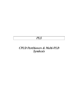
Figure 1-1 shows how Xilinx ABEL fits into the Xilinx FPGA design
flow, and Figure 1-2 shows the files used and created in the FPGA
design process.
1-2
Xilinx Development System
Chapter.book : ch1.doc
3 Tue Sep 17 12:21:10 1996
Introduction
Schematic
Editor
XDM
Text Editor
XABEL
ABL file
AHDL2X
PLASimX
functional
simulation
ABL2XNF
(AHDL2X,BLIFOPTX,
SynthX)
Schematic-toXNF Translator
BLIFOPTX
XNF file
XNF file
XAS file
Pre-Processors
Optimization
and
XNF
Translation
SynthX
XSF file
XAS file
XNF file
XNFMerge
XSF file
XFF file
XSimMake
functional
simulation
XNFPrep
4K,4KA, 4KH, 5K
2K,3K, 3KA, 3KL
Simulator
PGF file
XNFMap
XNF to Simulator
PPR
Guide
File
MAP file
LCA file
LCA2XNF
3KL,
3KA
PPR
2K,3K
XNFBA
LCA2XNF
APR
Guide
File
Guide
File
LCA file
LCA file
MakeBits
Download
or XChecker
MakePROM
X4056
Figure 1-1 Xilinx ABEL in the Xilinx FPGA Design Flow
Xilinx ABEL User Guide
1-3
Chapter.book : ch1.doc
4 Tue Sep 17 12:21:10 1996
Xilinx ABEL User Guide
XDM
XABEL
Xilinx
.abl
Design Synthesis
Simulation
AHDL2X
.lst
.dmc .tmv
AHDL2X
.bl0
.dmc
BLIFOPTX
STATEX
.xnf
Xilinx
.tmv
BLIFOPTX
.tt1
.bl1
Synthx
.tt1
PLASIMX
.xsf
.sm#
IMPROVEX
.xnf
.rep
top.xnf file
.xas
synthx.log
err.err
TRANSLATE → XMake
.lca
.bit
X4044
Figure 1-2 Files Involved in FPGA Processing
1-4
Xilinx Development System
Chapter.book : ch1.doc
5 Tue Sep 17 12:21:10 1996
Introduction
EPLDs
The EPLD design flow is illustrated in Figure 1-3 and Figure 1-4.
XABEL
JED file
JED2HDLX
ABL file
ABL file
ABL file
AHDL2X
BLIFOPTX
PLA2EQNX
XEPLD
Top-Level
PLUSASM
file from XABEL
Included
PLUSASM
file from XABEL
Included
PLUSASM
file from XABEL
FITEQN Command
Report file
VMH file
MakePRG
Intel HEX prog.file
MakeJED
JEDEC prog.file
XSimMake
OrCAD/Viewlogic sim.file
VMH2XNF
XNF file
For Third-Party
Simulators
X4520
Figure 1-3 Xilinx ABEL Design Flow for Behavioral Designs
Xilinx ABEL User Guide
1-5
Chapter.book : ch1.doc
6 Tue Sep 17 12:21:10 1996
Xilinx ABEL User Guide
XABEL
JED file
JED2HDLX
ABL file
ABL file
ABL file
AHDL2X
BLIFOPTX
Third-Party
Schematics
PLA2EQNX
XEPLD
PLUSASM PLD file
PLUSASM PLD file
PLUSASM PLD file
Schematic Netlist file
Report file
FITNET Command
VMH file
MakePRG
Intel HEX prog.file
MakeJED
JEDEC prog.file
XSimMake
VMH2XNF
OrCAD/Viewlogic sim.file
XNF file
For Third-Party
Simulators
X4518
Figure 1-4 Xilinx ABEL Design Flow for Schematic Designs
You have a wide variety of options for creating your EPLD design.
1-6
●
You can create a completely behavioral design, or you can use
behavioral modules in a schematic design.
●
You can use only ABL files, or you can mix ABL files with
PALASM, PLUSASM, or JEDEC files converted with the
JED2HDLX utility.
●
You can take advantage of special architectural features of Xilinx
EPLD devices in ABL files by including PLUSASM Property
statements.
Xilinx Development System
Chapter.book : ch1.doc
7 Tue Sep 17 12:21:10 1996
Introduction
●
After you have integrated your design in XDM, you can create
programming files in Intel Hex or JEDEC format.
●
You can create timing simulation models for OrCAD, Viewlogic,
or other third-party simulators.
Features
This section briefly describes the major features available in this
version of Xilinx ABEL.
XABEL Editor
The Xilinx ABEL front end consists of a menu-based editor called
XABEL. XABEL calls various back-end processors to convert an
ABEL-HDL (ABL) source file to an XNF file that can be merged with
other XNF files.
XABEL supports complete designs for EPLDs only. Xilinx requires
that FPGA designs entered using Xilinx ABEL represent only part of
the complete design, that is, that the schematic contain typically only
a module defined by state machine or equation entry. The nonschematic (ABEL-HDL) portion of the design is created using the
XABEL editor or a word processor that produces ASCII text and then
is processed to generate an XNF file. XMake subsequently processes
the complete FPGA design. XMake can also process the whole design
from the ABL file. XEMake processes EPLD designs.
State Encoding
You can describe symbolic or encoded state machines in Xilinx ABEL.
Either type can be implemented with one-hot encoding (OHE),
binary encoding, or a hybrid of OHE and binary called standard
encoding. A detailed description of these types of encoding is given
in the ‘‘State Machine Design Methodology” chapter.
Xilinx ABEL User Guide
1-7
Chapter.book : ch1.doc
8 Tue Sep 17 12:21:10 1996
Xilinx ABEL User Guide
Simulation
You can perform several types of simulation when you use Xilinx
ABEL:
●
Functional simulation, using PLASimX, of the ABEL-HDL source
file in Xilinx ABEL
●
Unit-delay simulation, using XSimMake, of the whole design from
the flattened schematic (for FPGAs only)
●
Worst-case timing simulation, using XSimMake, after placement
and routing
FPGA Area and Speed Optimization
Using the Area and Speed options of the Compile ➝ Xilinx FPGA
Options command (Options ➝ Xilinx FPGA Netlist command on
workstations), you can choose whether to optimize for area or speed
during logic optimization. If you elect to optimize for area with the
Area option, the ImproveX utility tries to make the design as small as
possible; when you optimize for speed with the Speed option, it tries
to make the design run as fast as possible. When you select the
Standard option, it tries to make the design as fast as possible while
meeting the area constraints, if they are specified with the CLB Limit
option. Otherwise, ImproveX attempts to achieve a reasonable
solution instead of optimizing for either speed or area.
FPGA Level Specifications
Level specifications optimize logic to a specific number of levels.
Using designated keywords in the ABEL-HDL file, which are listed in
the ‘‘ABEL-HDL for FPGAs” chapter, you can specify four types of
timing requirements as an alternative to the area-speed optimization
just described. You can specify the maximum number of CLB levels
on the following paths in the synthesized portion of your design:
1-8
●
Flip-flop to flip-flop
●
Flip-flop to output pin
●
Input pin to flip-flop
●
Pure combinatorial logic paths in the module
Xilinx Development System
Chapter.book : ch1.doc
9 Tue Sep 17 12:21:10 1996
Introduction
If you specify these timing requirements in the ABEL-HDL file, Xilinx
ABEL optimizes for area while trying to meet the specified speed
constraints. These constraints act only as guiding parameters for
logic synthesis, because actual delay is difficult to predict. They are
valid only when you choose the Standard optimization option of the
Compile ➝ Xilinx FPGA Options command on PCs (Options ➝
Xilinx FPGA Netlist command on workstations); otherwise, they are
ignored.
The output XNF file does not contain any TIMESPEC symbols. You
must specify them for the complete design in the higher-level
schematic.
FPGA Mapping
Through the Xilinx Property Map statement in the ABEL-HDL file for
FPGAs, you can specify that the subnetwork between the output pin
and the specified inputs be mapped into one CLB using F, G, and H
function generators. This capability allows you a control similar to
that which FMAP and HMAP constraints give for schematic entry. At
most, a map can have nine inputs for XC4000 designs and five for
XC3000 designs. The Xilinx Property Map keyword is discussed in
detail in the ‘‘ABEL-HDL for FPGAs” chapter.
Signal Saving
Normally only pin names are preserved in the final XNF file that
Xilinx ABEL produces for FPGAs; intermediate nodes and signals
may disappear. You can place a keyword in the ABEL-HDL file to
save the specified signal name in the final XNF file. However, you
must also declare the signal as a node in this file.
For EPLD devices, you can use Property statements to direct the
EPLD fitting software to keep intermediate nodes visible for
simulation.
Incompletely Specified FPGA State Machines
For FPGAs, you can determine how SynthX processes incompletely
specified state machines. A netlist compilation option gives you the
choice of having the state machine automatically transition into the
initial state; having it stay in the current state, thus forcing it to
completion; or indicating that you do not care how the machine
Xilinx ABEL User Guide
1-9
Chapter.book : ch1.doc
10 Tue Sep 17 12:21:10 1996
Xilinx ABEL User Guide
behaves under unspecified input conditions, so that state machine
behavior is unpredictable for certain input conditions. The Compile
➝ Xilinx FPGA Options (Options ➝ Xilinx FPGA Netlist on
workstations) ➝ State Machine Options ➝ Go To Initial State, Stay In
Current State, and Don’t Care commands implement these options,
respectively.
FPGA State Machine Speed Optimization
SynthX provides an option for state machine speed optimization
using state-splitting techniques, resulting in a faster design
implementation at the expense of a small number of extra CLBs. On
the basis of one-hot encoding, in which one flip-flop is used for a
state, SynthX tries to reduce the number of logic levels in the critical
path by using more than one flip-flop to represent the same state. The
state machine is in a particular state if any of the flip-flops
representing that state are set ‘‘on.” SynthX automatically decides
which states to split.
The State Machine Speed Optimization option appears on the dialog
box activated by the Compile ➝ Xilinx FPGA Options command on
PCs and the Options ➝ Xilinx FPGA Netlist command on
workstations. By default, this option is turned off. Turn it on only if
you want a faster circuit at the expense of additional CLBs.
Flip-Flop Support
Xilinx ABEL supports D, JK, T, and synchronous SR flip-flops. SynthX
automatically maps JK, T, and SR flip-flops into D flip-flops, which
are the only type supported by the FPGA architecture. It uses dot
extensions to implement flip-flop control signals. The ‘‘ABEL-HDL
for FPGAs” chapter lists and describes these dot extensions.
PLA2EQNX automatically translates these functions into the
appropriate syntax for Xilinx EPLD devices.
You can implement asynchronous latches with equations but not with
the asynchronous latch dot extension, .L.
Full EPLD Design Support
Xilinx ABEL supports complete design entry for EPLDs without the
need for schematic entry. It also supports partial designs in a
schematic environment just as it does for FPGAs. You can specify the
1-10
Xilinx Development System
Chapter.book : ch1.doc
11 Tue Sep 17 12:21:10 1996
Introduction
required pinout using normal ABEL syntax and access all features of
the EPLD devices using Property statements.
Automatic Design Updating
Xilinx ABEL has an auto-updating command, called Options ➝ Auto
Update on PCs and Options ➝ Auto-Make on workstations, that
automatically updates input files whenever you select a command
that uses these files and they are out of date or missing. If running the
programs that produce these files is required for the updating, this
option runs them automatically. It is on by default.
When this option is turned off, Xilinx ABEL runs the programs that
produce the input files.
XMake, XEMake, and XSimMake
For FPGAs, XMake automatically runs the translation programs
required to convert your design into an XNF file. It accepts as input
either a schematic or an ABEL-HDL file. You can run XMake in
interactive or batch mode.
For EPLDs, you can run XEMake after generating PLUSASM files.
XEMake can process both schematic and fully behavioral designs.
For both FPGAs and EPLDs, XSimMake can automatically generate
the VSM netlist required for simulation.
Unsupported Features
Xilinx ABEL does not support the following language features:
●
For FPGAs, bidirectional I/O pins specified in ABEL-HDL
●
Place and route constraints for FPGAs, except for some mapping
and timing constraints specified through Xilinx properties. These
property keywords are described in detail in the ‘‘ABEL-HDL for
FPGAs” chapter; all others are discussed in the Xilinx Reference
Guide.
●
Explicit utilization of special FPGA features within ABEL, such as
ROMs, RAMs, edge decoders, IOB flip-flops, IOB three-state
buffers, and fast carry logic
Xilinx ABEL User Guide
1-11
Chapter.book : ch1.doc
12 Tue Sep 17 12:21:10 1996
Xilinx ABEL User Guide
●
If-Then statements that are not state-exclusive, that is, duplicate If
conditions that transition to two different states
●
FPGA input and output flip-flops, which must be instantiated
schematically. Xilinx ABEL supports complete EPLD designs.
●
XSF file generation for EPLD devices
●
Area/speed optimization, timing specification, and incompletely
specified state machines for EPLD devices
●
Automatic encoding — that is, selection of the optimal encoding
scheme by the software — specifically for EPLD devices
Programs and Files Used
Xilinx ABEL uses the following programs during ABEL-HDL design
processing:
1-12
●
Xilinx Design Manager (XDM) invokes XABEL from the Design
Entry menu.
●
XABEL is the basic Xilinx ABEL design environment. It consists of
a text editor, AHDL2X, BLIFOPTX, PLASimX, SynthX, ABL2XNF,
and PLA2EQNX.
●
AHDL2X compiles the source ABL file, checks for the correct
syntax, expands macros, acts on directives, and produces an Open
ABEL II (BL0) file and a test vector (TMV) file.
●
BLIFOPTX translates and optimizes the Open ABEL II (BL0) file
output by AHDL2X. For simulation, it produces a PLA (TT1) file,
which the PLASimX simulator accepts. For FPGA synthesis, it
optimizes the BL0 file to produce an optimized Open ABEL I
(BL1) file. For EPLDs, it optimizes the BL0 file to produce an
optimized PLA (TT2) file.
●
PLASimX simulates equations using a PLA (TT1) file and test
vector (TMV) files. It outputs an SM# file.
●
PLA2EQNX reads the PLA (TT2) file and generates PLUSASM
equations for EPLD devices. This input is submitted to the EPLD
fitter, which converts the design into a programming file for a
specific application.
●
SynthX runs StateX and ImproveX for FPGA devices. It produces
an XNF file, an XSF file, and an XAS file.
Xilinx Development System
Chapter.book : ch1.doc
13 Tue Sep 17 12:21:10 1996
Introduction
●
XMake automatically translates FPGA design files from ABEL to
XNF by invoking ABL2XNF.
●
ABL2XNF runs AHDL2X, BLIFOPTX, and SynthX in batch mode
and translates ABL files into XNF files for FPGAs.
●
ABL2PLD runs AHDL2X, BLIFOPTX, and PLA2EQNX for
EPLDs.
●
StateX performs logic synthesis on files described in Open ABEL
format and creates an XNF file.
●
ImproveX optimizes combinatorial logic within XNF files for
FPGAs.
In addition, Xilinx ABEL offers other programs that you can call to
perform specific functions that are not part of the main Xilinx ABEL
design flow.
●
JED2HDLX converts a JEDEC file to an ABL file. It is described in
detail in the ‘‘JEDEC and PALASM Files” chapter of this manual.
●
SymGen reads a Xilinx ABEL-generated or user-created XSF file
containing the symbol name and input and output names and
creates a macro file for OrCAD and a symbol for Viewlogic. The
OrCAD Draft schematic editor reads this macro file and creates a
functional block that references a Xilinx ABEL-created XNF file.
Viewlogic PROcapture reads the symbol and incorporates it into
the schematic. Instructions for using SymGen are given in the
‘‘How to Use Xilinx ABEL” chapter of this manual.
●
CleanupX deletes intermediate files created by Xilinx ABEL. It is
described in detail in the ‘‘How to Use Xilinx ABEL” chapter of
this manual.
Table 1-1 shows the files produced by these programs.
Xilinx ABEL User Guide
1-13
Chapter.book : ch1.doc
14 Tue Sep 17 12:21:10 1996
Xilinx ABEL User Guide
Table 1-1 Xilinx ABEL Files Used During Processing
File
1-14
Description
ABL
ABEL-HDL source file
LST
Compiler listing file generated when you select the
Compile Options command (Options Compile on
workstations)
DMC
Design manager control file that associates the source
file name with the XABEL software output file
err.err
Error file created during processing
TT1
ABEL PLA file used by PLASimX
TT2
PLA file containing equations used by PLA2EQNX
BL0
Open ABEL II file
BL1
Open ABEL I file
TMV
Test vector file used for simulation with PLASimX
REP
Report file from SynthX
synthx.log
Log file of screen output containing errors and
warnings
SM#
Simulation output from PLASimX
XNF
Xilinx Netlist Format file, output by SynthX, that
contains the synthesized design
XAS
Xilinx Netlist Format file, output by SynthX, that
contains the synthesized design represented by
primitive symbols that can be incorporated by XSimMake for functional simulation.
XSF
SynthX output file that is input to SymGen, the symbol generator. SymGen automatically generates the
schematic symbol for the ABEL module.
PLD
PLA2EQNX output file in PLUSASM format that is
input to the EPLD fitter
Xilinx Development System
Chapter.book : ch1.doc
15 Tue Sep 17 12:21:10 1996
Introduction
Documentation
The Xilinx ABEL documentation consists of two separate manuals:
the Xilinx ABEL Software Design Reference Manual from Data I/O and
this manual, the Xilinx ABEL User Guide from Xilinx. Each of these
manuals covers different aspects of designing with Xilinx ABEL, but
together they provide a complete reference for this design
environment.
The Xilinx ABEL User Guide is a general reference to ABEL-HDL and
how to use it when creating designs. It discusses the ABEL-HDL
syntax, the features of Xilinx ABEL, state machine methodology,
step-by-step instructions for using Xilinx ABEL, EPLD processing,
and a list of Xilinx ABEL commands. In addition, it includes
examples that illustrate the topics discussed.
Some topics covered in the Xilinx ABEL Software Design Reference
Manual are not pertinent to Xilinx designs. To minimize confusion, it
is recommended that you use the Xilinx ABEL User Guide as your
primary reference, and use the Xilinx ABEL Software Design Reference
Manual as a supplement.
You can order extra copies of these two manuals from your local
Xilinx distributor or Xilinx sales office.
All example files referred to in the Xilinx ABEL User Guide can be
found in the \$XACT\examples\xabel\designs directory for PCs
and in the /$XACT/examples/xabel/designs directory for
workstations.
Xilinx ABEL User Guide
1-15
Chapter.book : ch1.doc
16 Tue Sep 17 12:21:10 1996
Xilinx ABEL User Guide
1-16
Xilinx Development System
Chapter.book : covch2
17 Tue Sep 17 12:21:10 1996
Xilinx ABEL
User Guide
Xilinx ABEL User Guide — 0401317 01
State Machine Design
Methodology
Printed in U.S.A.
Chapter.book : covch2
18 Tue Sep 17 12:21:10 1996
Xilinx ABEL User Guide
Xilinx Development System
Chapter.book : ch2.doc
1 Tue Sep 17 12:21:10 1996
Chapter 2
State Machine Design Methodology
State machine design typically starts with the translation of a concept
into a “paper design,” usually in the form of a state diagram or a
bubble diagram. The paper design is converted to a state table and
finally into the source code itself. To illustrate the process of
developing state machines, this chapter presents an example in
which a state machine repetitively sequences through the five
numbers 9, 5, 1, 2, and 4. These numbers are then displayed on the
7-segment display of a Xilinx XC3000 demonstration board.
State Machine Example
The state machine used as an example has four modes, which can be
selected by two inputs: DIR (direction) and SEQ (sequence). DIR
reverses the sequence direction; SEQ alters the sequence by swapping
the position of two of the numbers in the sequence. When the
machine is turned on, it starts in the initial state and displays the
number 9. It then sequences to the next number shown, depending
on the input. This sequence is summarized in Table 2-1.
Table 2-1 State Relationships
SEQ
DIR
1
1
9➝5➝1➝2➝4➝9 . . .
1
0
9➝4➝2➝1➝5➝9 . . .
0
1
9➝5➝2➝1➝4➝9 . . .
0
0
9➝4➝1➝2➝5➝9 . . .
Xilinx ABEL User Guide — 0401317 01
Sequence of Displayed Number
2-1
Chapter.book : ch2.doc
2 Tue Sep 17 12:21:10 1996
Xilinx ABEL User Guide
Conceptual descriptions show the state progression and controlling
modes, but they do not clearly show how change conditions result.
State Diagram
The state diagram is a pictorial description of state relationships.
Figure 2-1 gives an example of a state diagram. Even though a state
diagram provides no extra information, it is generally easier to
translate a state diagram into a state table. Each circle contains the
name of the state, while arrows to and from the circles show the
transitions between states and the input conditions that cause state
transitions. These conditions are written next to each arrow.
Display = 9
S9
dir = 0
dir = 1
Display = 5
S5
seq = 1
&
dir = 0
dir = 1
Display = 4
0
seq
dir =
=0&
0&
seq
=1
ir
= 0 & dir = 1 seq =
&d
dir =
seq 1
0
or
seq = 1
seq = 1
=0
&
dir
&
&
dir = 1
0
dir = 1
q=
e
s
seq = 0 & dir = 1
S4
Display = 1
dir = 0
S4
seq = 1
&
dir = 0
S2
seq = 1 & dir = 0
or
seq = 0 & dir = 1
Display = 2
X2025
Figure 2-1 State Diagram
State Table
The next step is to create a step-by-step description of the state
diagram in a form compatible with the requirements of the ABEL
Hardware Description Language (ABEL-HDL), which is the state
machine language that Xilinx ABEL uses. This description is typically
written as a list of present states, next states, and conditions for
change to occur, as shown in Table 2-2. It indicates the combinations
of inputs that can transition from one state to the next.
2-2
Xilinx Development System
Chapter.book : ch2.doc
3 Tue Sep 17 12:21:10 1996
State Machine Design Methodology
Table 2-2 Present States, Next States, and Conditions
Present State
Next State
Conditions
S9
S5
DIR = 1
S9
S4
DIR = 0
S5
S1
SEQ = 1 & DIR = 1
S5
S9
DIR = 0
S5
S2
SEQ = 0 & DIR = 1
S1
S5
SEQ = 1 & DIR = 0
S1
S4
SEQ = 0 & DIR = 1
S1
S2
SEQ = 1 & DIR = 1
or
SEQ = 0 & DIR = 0
S2
S4
SEQ = 1 & DIR = 1
S2
S5
SEQ = 0 & DIR = 0
S2
S1
SEQ = 1 & DIR = 0
or
SEQ = 0 & DIR = 1
S4
S1
SEQ = 0 & DIR = 0
S4
S2
SEQ = 1 & DIR = 0
S4
S9
DIR = 1
As you become more familiar with the ABEL-HDL syntax, the state
table begins to look more like the form that the language needs.
Eventually it also becomes more natural to convert a concept straight
into the state table without needing a state diagram or “present statenext state” list to clarify the concept. In ABEL-HDL, the table is
denoted by the State_diagram keyword. The ABEL-HDL syntax is
explained in the ‘‘State Machine Examples” section of this chapter
and in the ‘‘ABEL-HDL for FPGAs” chapter.
The final step is to enter the “present state-next state” list into a file
called the ABEL-HDL (ABL) file. For this example, the state table
looks like the following.
Xilinx ABEL User Guide
2-3
Chapter.book : ch2.doc
4 Tue Sep 17 12:21:10 1996
Xilinx ABEL User Guide
state s9:
if (dir) then s5
else s4;
state s5:
if (!dir) then s9
else if (seq & dir) then s1
else s2;
state s1:
if (seq !$ dir) then s2
else if (seq) then s5
else s4;
state s2:
if (seq $ dir) then s1
else if (!seq) then s5
else s4;
state s4:
if (dir) then s9
else if (!seq) then s1
else s2;
State Machine Implementation
A state machine requires memory and the ability to make decisions.
The actual hardware used to implement a state machine consists of
state registers (flip-flops) and combinatorial logic (gates). State
registers store the current state until the next state is calculated, and a
logic network performs functions that calculate the next state on the
basis of the present state and the state machine inputs. Figure 2-2
shows the transition logic transitioning through the state registers to
the output decoder logic.
Feedback
Logic Gates
State
Registers
Outputs
Inputs
Outputs
X4635
Logic Gates
Figure 2-2 Parts of a State Machine
The amount of logic used to calculate the next state varies according
to the type of state machine being implemented. You must choose the
2-4
Xilinx Development System
Chapter.book : ch2.doc
5 Tue Sep 17 12:21:10 1996
State Machine Design Methodology
most efficient design approach, depending on the hardware in which
the design will be implemented. In general, state machines designed
with Xilinx ABEL should use less than 256 states.
Encoding Techniques
The states in a state machine are represented by setting certain values
in the set of state registers. This process is called state assignment or
state encoding.
There are many ways to arrange, or encode, state machines. For
example, for a state machine of five states, you can use three flip-flops
set to values for states 000, 001, 010, 011, 100, which results in a highly
encoded state machine implementation. You can also use five flipflops set to values 00001, 00010, 00100, 01000, 10000, that is, one flipflop per state, which results is a one-hot-encoded state machine
implementation. State encoding has a substantial influence on the
size and performance of the final state machine implementation. This
section describes the encoding techniques that you can use with
Xilinx ABEL to create FPGA and EPLD designs. In addition, it gives
an example and a detailed description of a symbolic and an encoded
state machine with similar functions.
Symbolic and Encoded State Machines
A symbolic state machine makes no reference to the actual values
stored in the state register for the different states in the state table.
Therefore, the software determines what these values should be; it
can implement the most efficient scheme for the architecture being
targeted or the size of the machine being produced.
All that is defined in a symbolic state machine is the relationship
among the states in terms of how input signals affect transitions
between them, the values of the outputs during each state, and in
some cases, the initial state.
An encoded state machine requires the same definition information
as a symbolic machine, but in addition, it requires you to define the
value of the state register for each state.
You can implement both symbolic and encoded state machines with
any type of encoding described in the following sections.
Xilinx ABEL User Guide
2-5
Chapter.book : ch2.doc
6 Tue Sep 17 12:21:10 1996
Xilinx ABEL User Guide
Symbolic state machines are supported for EPLDs, but they are less
efficient than encoded state machines. When symbolic state machines
are used for EPLDs, the Xilinx Property statements described in the
‘‘ABEL-HDL for FPGAs” chapter are ignored.
Compromises in State Machine Encoding
A good state machine design must optimize the amount of
combinatorial logic, the fanin to each register, the number of registers,
and the propagation delay between registers. However, these factors
are interrelated, and compromises between them may be necessary.
For example, to increase speed, levels of logic must be reduced.
However, fewer levels of logic result in wider combinatorial logic,
that is, in a higher fanin than can be implemented efficiently given the
limited number of fanins imposed by the FPGA architecture.
As another example, you must factor the logic to decrease the gate
count; that is, you must extract and implement shared terms using
separate logic. Factoring reduces the amount of logic but increases
the levels of logic between registers, which slows down the circuit. In
general, the performance of a highly encoded state machine
implemented in an FPGA device drops as the number of states grows,
because of the wider and deeper decoding that is required for each
additional state. EPLDs are less sensitive to this problem because they
allow a higher fanin.
Binary Encoding
Using the minimum number of registers to encode the machine is
called binary, or maximal, encoding, because the registers are used to
their maximum capacity. Each register represents one bit of a binary
number. The example discussed earlier in this chapter has five states,
which can be represented by three bits in a binary-encoded state
machine.
Although binary encoding keeps the number of registers to a
minimum, it generally increases the amount of combinatorial logic
because more combinatorial logic is required to decode each state.
Given this compromise, binary encoding works well when
implemented in Xilinx EPLD devices, where gates are wide and
registers are few.
2-6
Xilinx Development System
Chapter.book : ch2.doc
7 Tue Sep 17 12:21:10 1996
State Machine Design Methodology
One-Hot Encoding
One-hot encoding takes an approach that is opposite to that of binary
encoding. In one-hot encoding, an individual state register is
dedicated to one state. Only one flip-flop is active, or hot, at any one
time. If the example discussed earlier in this chapter is implemented
as a one-hot encoded state machine, it uses five state registers.
There are two ways that one-hot encoding can significantly reduce
the amount of combinatorial logic used to implement a state
machine. As noted earlier, highly encoded designs tend to require
many high fanin logic functions to interpret the inputs. One-hot
encoding simplifies this interpretation process, because each state has
its own register, or flip-flop. As a result, the state machine is already
“decoded,” so the state of the machine is determined simply by
finding out which flip-flop is active. One-hot encoding reduces the
width of the combinatorial logic and, as a result, the state machine
requires fewer levels of logic between registers, reducing its
complexity and increasing its speed.
Although one-hot encoding can be used for EPLDs and FPGAs, it is
better suited to FPGAs.
See the “Accelerate FPGA Macros with One-Hot Approach”
appendix of this manual for a detailed description of one-hot
encoding and its applications.
One-Hot Encoding in Xilinx FPGA Architecture
One-hot encoding is well-suited to Xilinx FPGAs because the Xilinx
architecture is rich in registers, while each configurable logic block
(CLB) has a limited number of inputs. As a result, state machine
designs that require few registers, many combinatorial elements, and
large fanin do not take full advantage of these resources. In general, a
one-hot state machine implemented in a Xilinx FPGA minimizes both
the number of CLBs and the levels of logic used. As a result, the
circuit can run much faster than it would using binary encoding.
Limitations
In some cases, the one-hot method may not be the best encoding
technique for a state machine implemented in a Xilinx device. For
example, if the number of states is small, the speed advantages of
Xilinx ABEL User Guide
2-7
Chapter.book : ch2.doc
8 Tue Sep 17 12:21:10 1996
Xilinx ABEL User Guide
using the minimum amount of combinatorial logic may be offset by
delays resulting from inefficient CLB use. In general, it is worthwhile
to consider alternative encoding schemes for machines with fewer
than eight states. One approach is to blend one-hot encoding with
other encoding techniques in order to best use the resources of the
Xilinx device. This approach in Xilinx ABEL is called standard
encoding, which is described in the next section.
Standard Encoding
Sometimes the best results are obtained using a method that
incorporates features of both binary and one-hot encoding. Standard
encoding forms clusters of states and uses binary encoding for each
cluster. One-hot encoding is a special case of standard encoding in
which each cluster contains exactly one state. Binary encoding is a
special case in which all states belong to a single cluster.
Standard encoding can be used with FPGAs only.
Encoding for EPLDs
EPLD devices generally implement binary-encoded state machines
more efficiently. Binary encoding uses the minimum number of
registers. Each state is represented by a binary number stored in the
registers. Using as few registers as possible usually increases the
amount of combinatorial logic needed to interpret each state.
EPLD devices have wide gates and a large amount of combinatorial
logic per register, so it is best to start with binary encoding. If the
complexity of the state machine logic is such that binary encoding
exhausts all product term resources of an EPLD, try a slightly less
fully encoded state machine.
The syntax used to specify one-hot encoded state machines for
FPGAs is also supported for EPLD designs.
Using the @DCSET and @DCSTATE directives to indicate don’t-cares
explicitly often improves results during logic reduction.
State Machine Examples
This section provides an example of a symbolic state machine and an
encoded state machine. Both of these designs, after being translated
2-8
Xilinx Development System
Chapter.book : ch2.doc
9 Tue Sep 17 12:21:10 1996
State Machine Design Methodology
and merged with their respective schematic designs, display a 9, 5, 1,
2, and 4 on the 7-segment display of a Xilinx demonstration board.
See the ‘‘Design Examples” chapter in this manual for an example
showing how to process an ABEL-HDL file, merge it with a
schematic file, convert the resulting file into an LCA file, and
download it to a Xilinx demonstration board.
Symbolic State Machine Design
You can find this ABEL-HDL file, zipcode.abl, in the
\$XACT\examples\xabel\designs directory for PCs and in the
/$XACT/examples/xabel/designs directory for workstations. This
file targets an FPGA device, not an EPLD device.
module zipcode
title ’LCA, with symbolic state machine entry’
”clocks
clock
pin;
”control inputs
dir , seq , sync_input
pin;
”outputs
a , b , c , d , e , f , g
pin;
”state diagram declaration and assignment
sbit
s9 , s5 , s1 , s2 , s4
STATE_REGISTER
istype ’reg_D’;
STATE;
xilinx property ’Initialstate s9’;
”output
”
”
”
”
f
”
”
”
e
”
”
”
Xilinx ABEL User Guide
decoding
a
----|
| b
|
|
--g-|
| c
|
|
----d
_
|_|
|
a
b
c
d
e
=
=
=
=
=
_
|_
_|
_
| _| |_|
| |_
|
nine, five, two
nine, one, two, four
nine, five, one, four
two, five
two
2-9
Chapter.book : ch2.doc
10 Tue Sep 17 12:21:10 1996
Xilinx ABEL User Guide
”
”
”
f = nine, five, four
g = nine, five, two, four
Equations
sbit.clk = clock;
a
b
c
d
e
f
g
=
=
=
=
=
=
=
(s9 #
(s9 #
(s9 #
(s2 #
(s2);
(s9 #
(s9 #
s5 # s2);
s1 # s2 # s4);
s5 # s1 # s4);
s5);
s5 # s4);
s5 # s2 # s4);
State_Diagram sbit
”This state machine displays a 9, 5, 1, 2 or 4 on the 7”segment display of a 3020 demo board. DIR and SEQ are
”the external inputs. The display is defined by the
”state that the state machine is in. The sequencing is
”defined by the following table:
”DIR
”
”1
”0
”1
”0
”
2-10
SEQ
sequence
1
1
0
0
9
9
9
9
->
->
->
->
5
4
5
4
->
->
->
->
1
2
2
1
->
->
->
->
2
1
1
2
->
->
->
->
4
5
4
5
->
->
->
->
9
9
9
9
..
..
..
..
State s9:
if
else
( dir) then s5
s4;
State s5:
if
else if
else
(!dir) then s9
(seq) then s1
s2;
State s1:
if
( seq !$ dir ) then s2
else if
( seq) then s5
else
s4;
State s2:
if
else if
else
( seq $ dir) then s1
(!seq) then s5
s4;
State s4:
if
else if
else
( dir) then s9
(!seq) then s1
s2;
sync_reset s1:
sync_input;
Xilinx Development System
Chapter.book : ch2.doc
11 Tue Sep 17 12:21:10 1996
State Machine Design Methodology
TEST_VECTORS
([clock,dir,seq,sync_input]->[a,b,c,d,e,f,g])
[ .c. , 1 , 1 ,
1
]->[0,1,1,0,0,0,0];
[ .c. , 1 , 1 ,
0
]->[1,1,0,1,1,0,1];
[ .c. , 1 , 1 ,
0
]->[0,1,1,0,0,1,1];
[ .c. , 1 , 1 ,
0
]->[1,1,1,0,0,1,1];
[ .c. , 1 , 1 ,
0
]->[1,0,1,1,0,1,1];
[ .c. , 1 , 1 ,
0
]->[0,1,1,0,0,0,0];
[ .c. , 1 , 1 ,
0
]->[1,1,0,1,1,0,1];
[ .c. , 1 , 1 ,
0
]->[0,1,1,0,0,1,1];
[ .c. , 1 , 1 ,
0
]->[1,1,1,0,0,1,1];
”Change Direction
[ .c. , 0 , 1 ,
0
]->[0,1,1,0,0,1,1];
[ .c. , 0 , 1 ,
0
]->[1,1,0,1,1,0,1];
[ .c. , 0 , 1 ,
0
]->[0,1,1,0,0,0,0];
[ .c. , 0 , 1 ,
0
]->[1,0,1,1,0,1,1];
[ .c. , 0 , 1 ,
0
]->[1,1,1,0,0,1,1];
”Change Sequence
[ .c. , 1 , 0 ,
0
]->[1,0,1,1,0,1,1];
[ .c. , 1 , 0 ,
0
]->[1,1,0,1,1,0,1];
[ .c. , 1 , 0 ,
0
]->[0,1,1,0,0,0,0];
[ .c. , 1 , 0 ,
0
]->[0,1,1,0,0,1,1];
[ .c. , 1 , 0 ,
0
]->[1,1,1,0,0,1,1];
”Change Direction
[ .c. , 0 , 0 ,
0
]->[0,1,1,0,0,1,1];
[ .c. , 0 , 0 ,
0
]->[0,1,1,0,0,0,0];
[ .c. , 0 , 0 ,
0
]->[1,1,0,1,1,0,1];
[ .c. , 0 , 0 ,
0
]->[1,0,1,1,0,1,1];
[ .c. , 0 , 0 ,
0
]->[1,1,1,0,0,1,1];
”sync_input=1
”dir=seq=1
”dir=seq=1
”dir=seq=1
”dir=seq=1
”dir=seq=1
”dir=seq=1
”dir=seq=1
”dir=seq=1
->s1
->s2
->s4
->s9
->s5
->s1
->s2
->s4
->s9
”dir=0
”dir=0
”dir=0
”dir=0
”dir=0
seq=1
seq=1
seq=1
seq=1
seq=1
->s4
->s2
->s1
->s5
->s9
”dir=1
”dir=1
”dir=1
”dir=1
”dir=1
seq=0
seq=0
seq=0
seq=0
seq=0
->s5
->s2
->s1
->s4
->s9
”dir=1
”dir=1
”dir=1
”dir=1
”dir=1
seq=0
seq=0
seq=0
seq=0
seq=0
->s4
->s1
->s2
->s5
->s9
end
An explanation of this file follows.
An ABEL-HDL file must begin with a Module statement and end
with an End statement.
module zipcode
The Module statement includes an identifier, in this case ‘‘zipcode,”
that names the module as well as the resulting XNF or PLUSASM file.
The module name and its file name should be the same; otherwise,
the file name used for the intermediate files changes during
compilation.
title ’LCA, with symbolic state machine entry’
The Title statement, which is optional, gives a module a title that
appears in intermediate files created by the Xilinx ABEL software.
The Title statement is also used for informational purposes.
Xilinx ABEL User Guide
2-11
Chapter.book : ch2.doc
12 Tue Sep 17 12:21:10 1996
Xilinx ABEL User Guide
”clocks
clock
pin;
”control inputs
dir , seq , sync_input
pin;
”outputs
a , b , c , d , e , f , g
pin;
All of the signals associated with the pin declaration represent the
input and output signals of the file. To ensure connectivity, the signal
names in the pin declarations must match those appearing on the
functional block that represents the state machine in the schematic.
See Figure 2-1. The quotation marks before “clocks,” “control inputs,”
and “outputs” denote these words as comments.
”state diagram declaration and assignment
sbit
s9 , s5 , s1 , s2 , s4
STATE_REGISTER
istype ’reg_D’;
STATE;
The State_register keyword declares a symbolic state machine. The
State keyword declares states that appear in a symbolic state
machine. State_register must be used in conjunction with the State
keyword.
xilinx property ’Initialstate s9’;
The Xilinx Property Initialstate statement declares the power-up and
global reset state — ‘‘s9” in this example — for a symbolic state
machine. If this command is not specified, Xilinx ABEL randomly
selects a power-up state. This statement is not supported for Xilinx
EPLDs.
”output
”
”
”
”
f
”
”
”
e
”
”
2-12
decoding
a
----|
| b
|
|
--g-|
| c
|
|
----d
_
|_|
|
a
b
c
d
=
=
=
=
_
|_
_|
_
| _| |_|
| |_
|
nine , five , two
nine , one , two, four
nine , five , one , four
two , five
Xilinx Development System
Chapter.book : ch2.doc
13 Tue Sep 17 12:21:10 1996
State Machine Design Methodology
”
”
”
”
e = two
f = nine , five, four
g = nine , five, two, four
These comment lines show how each of the states relates to the 7segment display outputs. Using comments is recommended to
document the function of the state machine and associated equations.
Comments can appear anywhere in an ABEL-HDL file.
Equations
The Equations statement defines the beginning of a group of
equations in the ABEL-HDL file.
sbit.clk = clock;
All of the states associated with the ‘‘sbit” State_register declaration
now have the signal called ‘‘clock” as their clock source.
a
b
c
d
e
f
g
=
=
=
=
=
=
=
(s9 #
(s9 #
(s9 #
(s2 #
(s2);
(s9 #
(s9 #
s5 # s2);
s1 # s2 # s4);
s5 # s1 # s4);
s5);
s5 # s4);
s5 # s2 # s4);
These equations define the relationship between the outputs and the
states. The equations do not have to be related to the states. You can
include combinatorial or registered logic, which refers to signals not
used in the state machine. In this example, the equations decode the
current state for output on the 7-segment display on the
demonstration board.
State_Diagram sbit
The statements following the State_diagram keyword define the
operation of the state machine named “sbit.”
”
”
”
”
”
”
”
dir
seq
1
0
1
0
1
1
0
0
sequence
9
9
9
9
->
->
->
->
5
4
5
4
->
->
->
->
1
2
2
1
->
->
->
->
2
1
1
2
->
->
->
->
4
5
4
5
->
->
->
->
9
9
9
9
.....
.....
.....
.....
These comments indicate the sequencing of the state machine. The
‘‘dir” and ‘‘seq” signal names are the conditional inputs. The ‘‘dir”
Xilinx ABEL User Guide
2-13
Chapter.book : ch2.doc
14 Tue Sep 17 12:21:10 1996
Xilinx ABEL User Guide
signal name is ‘‘s5,” an external switch on the demonstration board,
and ‘‘seq” is ‘‘s6.”
State s9:
if
else
( dir) then s5
s4;
State s5:
if
else if
else
(!dir) then s9
(seq) then s1
s2;
State s1:
if
( seq !$ dir ) then s2
else if
( seq) then s5
else
s4;
State s2:
if
else if
else
( seq $ dir) then s1
(!seq) then s5
s4;
State s4:
if
else if
else
( dir) then s9
(!seq) then s1
s2;
These statements represent a “present state, condition, next state”
description of the state machine. The states can be listed in any order.
The Xilinx Property Initialstate statement defines the first state.
sync_reset
s1:
sync_input;
The Sync_reset statement specifies the state to which the state
machine moves when the associated equation — in this case, a single
input called Sync_input — is true.
TEST_VECTORS
([clock,dir,seq,sync_input]->[a,b,c,d,e,f,g])
[ .c. , 1 , 1 ,
1
]->[0,1,1,0,0,0,0];
[ .c. , 1 , 1 ,
0
]->[1,1,0,1,1,0,1];
[ .c. , 1 , 1 ,
0
]->[0,1,1,0,0,1,1];
[ .c. , 1 , 1 ,
0
]->[1,1,1,0,0,1,1];
[ .c. , 1 , 1 ,
0
]->[1,0,1,1,0,1,1];
[ .c. , 1 , 1 ,
0
]->[0,1,1,0,0,0,0];
[ .c. , 1 , 1 ,
0
]->[1,1,0,1,1,0,1];
[ .c. , 1 , 1 ,
0
]->[0,1,1,0,0,1,1];
[ .c. , 1 , 1 ,
0
]->[1,1,1,0,0,1,1];
”Change Direction
[ .c. , 0 , 1 ,
0
]->[0,1,1,0,0,1,1];
[ .c. , 0 , 1 ,
0
]->[1,1,0,1,1,0,1];
[ .c. , 0 , 1 ,
0
]->[0,1,1,0,0,0,0];
[ .c. , 0 , 1 ,
0
]->[1,0,1,1,0,1,1];
[ .c. , 0 , 1 ,
0
]->[1,1,1,0,0,1,1];
”Change Sequence
[ .c. , 1 , 0 ,
0
]->[1,0,1,1,0,1,1];
2-14
”sync_input=1
”dir=seq=1
”dir=seq=1
”dir=seq=1
”dir=seq=1
”dir=seq=1
”dir=seq=1
”dir=seq=1
”dir=seq=1
->s1
->s2
->s4
->s9
->s5
->s1
->s2
->s4
->s9
”dir=0
”dir=0
”dir=0
”dir=0
”dir=0
seq=1
seq=1
seq=1
seq=1
seq=1
->s4
->s2
->s1
->s5
->s9
”dir=1 seq=0
->s5
Xilinx Development System
Chapter.book : ch2.doc
15 Tue Sep 17 12:21:10 1996
State Machine Design Methodology
[ .c. , 1 , 0 ,
[ .c. , 1 , 0 ,
[ .c. , 1 , 0 ,
[ .c. , 1 , 0 ,
”Change Direction
[ .c. , 0 , 0 ,
[ .c. , 0 , 0 ,
[ .c. , 0 , 0 ,
[ .c. , 0 , 0 ,
[ .c. , 0 , 0 ,
0
0
0
0
]->[1,1,0,1,1,0,1];
]->[0,1,1,0,0,0,0];
]->[0,1,1,0,0,1,1];
]->[1,1,1,0,0,1,1];
”dir=1
”dir=1
”dir=1
”dir=1
seq=0
seq=0
seq=0
seq=0
->s2
->s1
->s4
->s9
0
0
0
0
0
]->[0,1,1,0,0,1,1];
]->[0,1,1,0,0,0,0];
]->[1,1,0,1,1,0,1];
]->[1,0,1,1,0,1,1];
]->[1,1,1,0,0,1,1];
”dir=1
”dir=1
”dir=1
”dir=1
”dir=1
seq=0
seq=0
seq=0
seq=0
seq=0
->s4
->s1
->s2
->s5
->s9
Test vectors, used by PLASimX during simulation, are a list of the
outputs expected for combinations of inputs. PLASimX initializes the
state machine to the state specified in the Xilinx Property Initialstate
statement.
To observe the initial state specified by the Initialstate keyword, add
the following statement before the first test vector:
[0, 1, 1, 1]->[1, 1, 1, 0, 0, 1, 1]; ”initialstate = s9
Specifying 0 for the ‘‘clk” value allows you to observe the initial state
during simulation.
end
The End statement denotes the end of the module.
Encoded State Machine Design
You can find this ABEL-HDL file, z_encode.abl, in the
\XACT\examples\xabel\designs directory for PCs and the
/$XACT/examples/xabel/designs directory for workstations. The
z_encode.abl file is the encoded state machine version of the
zipcode.abl file. This file produces efficient results for Xilinx EPLDs.
module z_encode
title ’Encoded version of zipcode.abl’
”clocks
clock
”control inputs
dir , seq , sync_input
pin;
pin;
”outputs
a , b , c , d , e , f , g
”state register flip flops
ff_2, ff_1, ff_0
Xilinx ABEL User Guide
pin;
node istype ’reg’;
2-15
Chapter.book : ch2.doc
16 Tue Sep 17 12:21:10 1996
Xilinx ABEL User Guide
”state register definition and state assignments
”The state which has all 0’s assigned to the state register
”flip-flops will be the state which is the initial reset
”state and the asynchronous reset state.
state_reg = [ff_2, ff_1, ff_0];
s9 = [ 0 , 0 , 0 ];
s5 = [ 0 , 0 , 1 ];
s1 = [ 0 , 1 , 0 ];
s2 = [ 0 , 1 , 1 ];
s4 = [ 1 , 0 , 0 ];
nine
= state_reg == s9;
five
= state_reg == s5;
one
= state_reg == s1;
two
= state_reg == s2;
four
= state_reg == s4;
”output
”
”
”
”
f
”
”
”
e
”
”
”
”
”
decoding
a
----|
| b
|
|
--g-|
| c
|
|
----d
_
|_|
|
a
b
c
d
e
f
g
=
=
=
=
=
=
=
_
|_
_|
_
| _| |_|
| |_
|
nine , five , two
nine , one , two, four
nine , five , one , four
two , five
two
nine , five, four
nine , five, two, four
Equations
state_reg.clk = clock;
”The following equations do the same as the ‘sync_reset ”s1:
sync_input;’ statement in the symbolic version of
”this state machine (zipcode.abl)
[ff_2,ff_0].sr = sync_input;
ff_1.sp = sync_input;
”output equations
a = (nine #
b = (nine #
c = (nine #
d = (two #
e = (two);
f = (nine #
g = (nine #
five # two);
one # two # four);
five # one # four);
five);
five # four);
five # two # four);
State_Diagram state_reg
2-16
Xilinx Development System
Chapter.book : ch2.doc
17 Tue Sep 17 12:21:10 1996
State Machine Design Methodology
”This state machine displays a 9, 5, 1, 2, or 4 on the 7”segment display of a 3020 demo board. DIR and SEQ are
”the external inputs. The display is defined by the
”state that the state machine is in. The sequencing is
”defined by the following table:
”
”DIR
SEQ
sequence
”
”1
1
9 -> 5 -> 1 -> 2 -> 4 -> 9 .....
”0
1
9 -> 4 -> 2 -> 1 -> 5 -> 9 .....
”1
0
9 -> 5 -> 2 -> 1 -> 4 -> 9 .....
”0
0
9 -> 4 -> 1 -> 2 -> 5 -> 9 .....
state
s9:
if
else
( dir) then s5
s4;
state
s5:
if
else if
else
(!dir) then s9
(seq) then s1
s2;
state
s1:
if
( seq !$ dir ) then s2
else if
( seq) then s5
else
s4;
state
s2:
if
else if
else
( seq $ dir) then s1
(!seq) then s5
s4;
state
s4:
if
else if
else
( dir) then s9
(!seq) then s1
s2;
TEST_VECTORS
([clock,dir,seq,sync_input]->[a,b,c,d,e,f,g])
[ .c. , 1 , 1 ,
1
]->[0,1,1,0,0,0,0];
[ .c. , 1 , 1 ,
0
]->[1,1,0,1,1,0,1];
[ .c. , 1 , 1 ,
0
]->[0,1,1,0,0,1,1];
[ .c. , 1 , 1 ,
0
]->[1,1,1,0,0,1,1];
[ .c. , 1 , 1 ,
0
]->[1,0,1,1,0,1,1];
[ .c. , 1 , 1 ,
0
]->[0,1,1,0,0,0,0];
[ .c. , 1 , 1 ,
0
]->[1,1,0,1,1,0,1];
[ .c. , 1 , 1 ,
0
]->[0,1,1,0,0,1,1];
[ .c. , 1 , 1 ,
0
]->[1,1,1,0,0,1,1];
”Change Direction
[ .c. , 0 , 1 ,
0
]->[0,1,1,0,0,1,1];
[ .c. , 0 , 1 ,
0
]->[1,1,0,1,1,0,1];
[ .c. , 0 , 1 ,
0
]->[0,1,1,0,0,0,0];
[ .c. , 0 , 1 ,
0
]->[1,0,1,1,0,1,1];
[ .c. , 0 , 1 ,
0
]->[1,1,1,0,0,1,1];
”Change Sequence
[ .c. , 1 , 0 ,
0
]->[1,0,1,1,0,1,1];
[ .c. , 1 , 0 ,
0
]->[1,1,0,1,1,0,1];
Xilinx ABEL User Guide
”sync_input=1
”dir=seq=1
”dir=seq=1
”dir=seq=1
”dir=seq=1
”dir=seq=1
”dir=seq=1
”dir=seq=1
”dir=seq=1
->s1
->s2
->s4
->s9
->s5
->s1
->s2
->s4
->s9
”dir=0
”dir=0
”dir=0
”dir=0
”dir=0
seq=1
seq=1
seq=1
seq=1
seq=1
->s4
->s2
->s1
->s5
->s9
”dir=1 seq=0
”dir=1 seq=0
->s5
->s2
2-17
Chapter.book : ch2.doc
18 Tue Sep 17 12:21:10 1996
Xilinx ABEL User Guide
[ .c. , 1 , 0 ,
[ .c. , 1 , 0 ,
[ .c. , 1 , 0 ,
”Change Direction
[ .c. , 0 , 0 ,
[ .c. , 0 , 0 ,
[ .c. , 0 , 0 ,
[ .c. , 0 , 0 ,
[ .c. , 0 , 0 ,
0
0
0
]->[0,1,1,0,0,0,0]; ”dir=1 seq=0
]->[0,1,1,0,0,1,1]; ”dir=1 seq=0
]->[1,1,1,0,0,1,1]; ”dir=1 seq=0
->s1
->s4
->s9
0
0
0
0
0
]->[0,1,1,0,0,1,1];
]->[0,1,1,0,0,0,0];
]->[1,1,0,1,1,0,1];
]->[1,0,1,1,0,1,1];
]->[1,1,1,0,0,1,1];
->s4
->s1
->s2
->s5
->s9
”dir=1
”dir=1
”dir=1
”dir=1
”dir=1
seq=0
seq=0
seq=0
seq=0
seq=0
end
An explanation of this file follows.
An ABEL-HDL file must begin with a Module statement and end
with an End statement.
module z_encode
The Module statement includes an identifier, in this case ‘‘z_encode,”
that names the module as well as the resulting XNF file. The module
name and its file name should be the same; otherwise, the file name
used for the intermediate files changes during the Xilinx ABEL
compilation process.
title ’Encoded version of zipcode.abl’
The Title statement, which is optional, gives a module a title that
appears in intermediate files created by the Xilinx ABEL software.
The Title statement is also used for documentation purposes.
”clocks
clock
”control inputs
dir , seq , sync_input
pin;
pin;”
outputs
a , b , c , d , e , f , g
pin;
All of the signals associated with pin declarations represent the input
and output signals of the file. The relative signal position in the pinlist
corresponds to the pin number of the PLD library component in the
schematic. ‘‘Clocks,” ‘‘control inputs,” and ‘‘outputs” are comment
lines.
”state register flip flops
ff_2, ff_1, ff_0
2-18
node istype ’reg’;
Xilinx Development System
Chapter.book : ch2.doc
19 Tue Sep 17 12:21:10 1996
State Machine Design Methodology
Each of the state registers must be defined explicitly in an encoded
state machine. In this example, three flip-flops are needed to
accommodate the five states. The Reg keyword defines the flip-flops
as D-type flip-flops.
”state register definition and state assignments
”The state which has all 0’s assigned to the state ”register
flip-flops will be the state which is the
”initial reset state and the asynchronous reset
”state.
state_reg = [ff_2, ff_1, ff_0];
s9 = [ 0 , 0 , 0 ];
s5 = [ 0 , 0 , 1 ];
s1 = [ 0 , 1 , 0 ];
s2 = [ 0 , 1 , 1 ];
s4 = [ 1 , 0 , 0 ];
These lines define the encoding of the state machine. Unlike a
symbolic state machine, encoding in an encoded state machine must
be defined explicitly.
nine
five
one
two
four
=
=
=
=
=
state_reg
state_reg
state_reg
state_reg
state_reg
==
==
==
==
==
s9;
s5;
s1;
s2;
s4;
These declarations equate nine, five, one, two, and four to the states
‘‘s9,” ‘‘s5,” ‘‘s1,” ‘‘s2,” and ‘‘s4,” respectively. ‘‘S9,” ‘‘s5,” ‘‘s1,” ‘‘s2,”
and ‘‘s4” cannot be used in equations in encoded state machines.
”output
”
”
”
”
f
”
”
”
e
”
”
”
”
”
decoding
a
----|
| b
|
|
--g-|
| c
|
|
----d
_
|_|
|
a
b
c
d
e
f
g
=
=
=
=
=
=
=
_
|_
_|
_
| _| |_|
| |_
|
nine, five, two
nine, one, two, four
nine, five, one, four
two, five
two
nine, five, four
nine, five, two, four”
These comment lines show how each of the states relates to the
7-segment display outputs. Using comments is recommended to
document the function of the state machine and associated equations.
Xilinx ABEL User Guide
2-19
Chapter.book : ch2.doc
20 Tue Sep 17 12:21:10 1996
Xilinx ABEL User Guide
Equations
The Equations keyword defines the beginning of a group of equations
in the ABEL-HDL file.
state_reg.clk = clock;
All of the flip-flops (“ff_2,” “ff_1,” “ff_0”) associated with the
State_reg declaration now have the signal called ‘‘clock” as their clock
source.
”The following equations do the same as the ‘sync_reset
”s1: sync_input;’ statement in the symbolic version of
”this state machine (zipcode.abl)
[ff_2,ff_0].sr = sync_input;
ff_1.sp = sync_input;
As explained in the comment lines, these two statements perform the
same function as the Sync_reset s1: Sync_input statement in the
zipcode.abl file. (Sync_reset and Async_reset can only be used with
symbolic state machines). These statements specify the state to which
the state machine moves when the associated equation — in this case,
a single input called ‘‘sync_input” — is true.
”output equations
a = (nine #
b = (nine #
c = (nine #
d = (two #
e = (two);
f = (nine #
g = (nine #
five # two);
one # two # four);
five # one # four);
five);
five # four);
five # two # four);
These equations define the relationship between the outputs and the
states. In this example, the equations decode the current state for
output on the 7-segment display on the demonstration board.
State_Diagram state_reg
The equations following the State_diagram keyword describe the
operation of the ‘‘state_reg” state machine.
”This state machine displays a 9, 5, 1, 2, or 4 on the
”7-segment display of a 3020 demo board. DIR and SEQ are
”the external inputs. The display is defined by the
”state that the state machine is in. The sequencing is
”defined by the following table:
”
”DIR
SEQ
sequence
”
2-20
Xilinx Development System
Chapter.book : ch2.doc
21 Tue Sep 17 12:21:10 1996
State Machine Design Methodology
”1
”0
”1
”0
1
1
0
0
9
9
9
9
->
->
->
->
5
4
5
4
->
->
->
->
1
2
2
1
->
->
->
->
2
1
1
2
->
->
->
->
4
5
4
5
->
->
->
->
9
9
9
9
.....
.....
.....
.....
These comments indicate the sequencing of the state machine. The
‘‘dir” and ‘‘seq” signal names are the conditional inputs. The ‘‘dir”
signal name is ‘‘s5,” an external switch on the demonstration board,
and ‘‘seq” is ‘‘s6.”
state
s9:
if
else
( dir) then s5
s4;
state
s5:
if
else if
else
(!dir) then s9
(seq) then s1
s2;
state
s1:
if
( seq !$ dir ) then s2
else if
( seq) then s5
else
s4;
state
s2:
if
else if
else
( seq $ dir) then s1
(!seq) then s5
s4;
state
s4:
if
else if
else
( dir) then s9
(!seq) then s1
s2;
These statements represent a “present state, condition, next state”
description of the state machine, just as in the zipcode.abl example.
The states can be listed in any order, since the first state (‘‘s9”) was
defined in the state register definitions and state assignments section.
In the zipcode.abl example, the first state was defined by the Xilinx
Property Initialstate keyword.
TEST_VECTORS
([clock,dir,seq,sync_input]->[a,b,c,d,e,f,g])
[ .c. , 1 , 1 ,
1
]->[0,1,1,0,0,0,0];
[ .c. , 1 , 1 ,
0
]->[1,1,0,1,1,0,1];
[ .c. , 1 , 1 ,
0
]->[0,1,1,0,0,1,1];
[ .c. , 1 , 1 ,
0
]->[1,1,1,0,0,1,1];
[ .c. , 1 , 1 ,
0
]->[1,0,1,1,0,1,1];
[ .c. , 1 , 1 ,
0
]->[0,1,1,0,0,0,0];
[ .c. , 1 , 1 ,
0
]->[1,1,0,1,1,0,1];
[ .c. , 1 , 1 ,
0
]->[0,1,1,0,0,1,1];
[ .c. , 1 , 1 ,
0
]->[1,1,1,0,0,1,1];
”Change Direction
[ .c. , 0 , 1 ,
0
]->[0,1,1,0,0,1,1];
[ .c. , 0 , 1 ,
0
]->[1,1,0,1,1,0,1];
[ .c. , 0 , 1 ,
0
]->[0,1,1,0,0,0,0];
Xilinx ABEL User Guide
”sync_input=1
”dir=seq=1
”dir=seq=1
”dir=seq=1
”dir=seq=1
”dir=seq=1
”dir=seq=1
”dir=seq=1
”dir=seq=1
->s1
->s2
->s4
->s9
->s5
->s1
->s2
->s4
->s9
”dir=0 seq=1
”dir=0 seq=1
”dir=0 seq=1
->s4
->s2
->s1
2-21
Chapter.book : ch2.doc
22 Tue Sep 17 12:21:10 1996
Xilinx ABEL User Guide
[ .c. , 0 , 1 ,
[ .c. , 0 , 1 ,
”Change Sequence
[ .c. , 1 , 0 ,
[ .c. , 1 , 0 ,
[ .c. , 1 , 0 ,
[ .c. , 1 , 0 ,
[ .c. , 1 , 0 ,
”Change Direction
[ .c. , 0 , 0 ,
[ .c. , 0 , 0 ,
[ .c. , 0 , 0 ,
[ .c. , 0 , 0 ,
[ .c. , 0 , 0 ,
0
0
]->[1,0,1,1,0,1,1]; ”dir=0 seq=1
]->[1,1,1,0,0,1,1]; ”dir=0 seq=1
->s5
->s9
0
0
0
0
0
]->[1,0,1,1,0,1,1];
]->[1,1,0,1,1,0,1];
]->[0,1,1,0,0,0,0];
]->[0,1,1,0,0,1,1];
]->[1,1,1,0,0,1,1];
”dir=1
”dir=1
”dir=1
”dir=1
”dir=1
seq=0
seq=0
seq=0
seq=0
seq=0
->s5
->s2
->s1
->s4
->s9
0
0
0
0
0
]->[0,1,1,0,0,1,1];
]->[0,1,1,0,0,0,0];
]->[1,1,0,1,1,0,1];
]->[1,0,1,1,0,1,1];
]->[1,1,1,0,0,1,1];
”dir=1
”dir=1
”dir=1
”dir=1
”dir=1
seq=0
seq=0
seq=0
seq=0
seq=0
->s4
->s1
->s2
->s5
->s9
Test vectors used during simulation are a list of the outputs expected
for combinations of inputs.
end
The End statement denotes the end of the module.
2-22
Xilinx Development System
Chapter.book : covch3
23 Tue Sep 17 12:21:10 1996
Xilinx ABEL
User Guide
ABEL-HDL for FPGAs
Xilinx ABEL User Guide — 0401317 01
Printed in U.S.A.
Chapter.book : covch3
24 Tue Sep 17 12:21:10 1996
Xilinx ABEL User Guide
Xilinx Development System
Chapter.book : ch3.doc
1 Tue Sep 17 12:21:10 1996
Chapter 3
ABEL-HDL for FPGAs
This chapter describes how to use the ABEL Hardware Description
Language (ABEL-HDL) when creating Xilinx FPGA designs.
Included are discussions of keywords, attribute assignments, dot
extensions, and pin and node assignments. See the “Supported
Device Types” appendix for a listing of supported device types.
The ‘‘XEPLD” chapter gives the ABEL-HDL syntax for EPLD designs.
For a list of the operators and the syntax that ABEL-HDL uses, see the
Xilinx ABEL Software Design Reference Manual from Data I/O.
Keywords
Xilinx ABEL recognizes seven keywords that simplify the creation of
state machines. These keywords are described in this section. All
other keywords noted in this manual are not specific to Xilinx ABEL;
you can find a description of them in the Xilinx ABEL Software Design
Reference Manual from Data I/O.
Keywords are not case-sensitive. Refer to the ‘‘State Machine Design
Methodology” chapter in this manual for information about where
keyword statements should be placed in the ABEL-HDL source file.
Xilinx Property Initialstate
The Xilinx Property Initialstate keyword defines the initial power-up
state. It instructs the compiler to arrange the logic so that the state
machine always goes to the specified state during power-up or global
reset. If you do not use this statement or the Async_reset statement,
the compiler chooses the initial state.
Note: Xilinx Property statements are FPGA-specific. For EPLDspecific properties, see the ‘‘XEPLD” chapter of this manual.
Xilinx ABEL User Guide — 0401317 01
3-1
Chapter.book : ch3.doc
2 Tue Sep 17 12:21:10 1996
Xilinx ABEL User Guide
Use the following syntax for the Xilinx Property Initialstate keyword:
xilinx property ’initialstate state_name’
The state register name is required if there are multiple state
machines in the module. In this case, use the following syntax:
xilinx property ’initialstate state_register_name
state_name’
Single or double quotation marks must be placed around Initialstate,
the state register name, and the state name.
Here is an example of the first form of this keyword:
xilinx property ’initialstate st01’;
Following is an example of the syntax used with multiple state
machines:
xilinx property ’initialstate sreg st01’;
During simulation, PLASimX initializes the state machine to the state
specified in the Xilinx Property Initialstate statement. To observe the
specified initial state, specify 0 (zero) for the clock input instead of .c.
for the first test vector. This specification allows you to observe the
initialization state in the simulation results.
The Xilinx Property Initialstate keyword applies to symbolic state
machines only.
Xilinx Property Map
The Xilinx Property Map keyword ensures that the subnetwork
between the output pin and the specified inputs is mapped into one
CLB. However, you can use the Xilinx Property Map statement only
to map non-registered signals into CLBs; you cannot use registered
signals. The syntax of this keyword is the following:
xilinx property ’map output_pin input1 input2 input3...’
Single or double quotation marks must be placed around Map and
the final input. Output_pin must be declared as an output pin or a
node. The output pin must be a combinatorial signal; it cannot be a
sequential signal. Input1 input2 input3 . . . must be declared as input
pins or nodes. Also, the map should be logically feasible.
3-2
Xilinx Development System
Chapter.book : ch3.doc
3 Tue Sep 17 12:21:10 1996
ABEL-HDL for FPGAs
For XC3000 designs, up to five inputs are allowed. The subnetwork is
mapped into a CLB using F and/or G generators.
For XC4000 designs, nine is the maximum number of inputs allowed.
The subnetwork is mapped into F, F and H, or F, G, and H function
generators, depending on the number of inputs and the mapping
logic.
Not all six-, seven-, eight-, or nine-input functions can fit into a CLB.
If ImproveX cannot fit the entire map into one CLB, it issues an error
message and stops processing.
You can use the Xilinx Property Map keyword with symbolic or
encoded state machines.
The ‘‘Design Examples” chapter gives examples showing how to use
the Xilinx Property Map statement.
Xilinx Property Save
Normally only pin names are preserved in the final XNF file that
Xilinx ABEL produces; intermediate nodes and signals may
disappear. The Xilinx Property Save keyword ensures that the
specified signal name is saved in the final XNF file. However, you
must also declare the signal as a pin or a node in the ABEL-HDL file;
otherwise, SynthX issues an error message. The syntax to use this
keyword is as follows:
xilinx property ’save signal_name’
You can use the Xilinx Property Save keyword with symbolic or
encoded state machines.
The ‘‘Design Examples” chapter gives examples showing how to use
the Xilinx Property Save statement.
Xilinx Property Dlc2s
The Xilinx Property Dlc2s keyword sets the maximum number of
logic levels on all paths from flip-flop to flip-flop. The syntax of this
command is the following:
xilinx property ’dlc2s maximum’
Xilinx ABEL User Guide
3-3
Chapter.book : ch3.doc
4 Tue Sep 17 12:21:10 1996
Xilinx ABEL User Guide
Here is an example of this syntax:
xilinx property ’dlc2s 4’
You can use the Xilinx Property Dlc2s keyword with symbolic or
encoded state machines.
Xilinx Property Dlp2s
The Xilinx Property Dlp2s keyword sets the maximum number of
logic levels on all paths from input pin to flip-flop. The syntax of this
command is the following:
xilinx property ’dlp2s maximum’
You can use the Xilinx Property Dlp2s keyword with symbolic or
encoded state machines.
Xilinx Property Dlp2p
The Xilinx Property Dlp2p keyword sets the maximum number of
logic levels on pure combinatorial logic paths in the module. The
syntax of this command is the following:
xilinx property ’dlp2p maximum’
You can use the Xilinx Property Dlp2p keyword with symbolic or
encoded state machines.
Xilinx Property Dlc2p
The Xilinx Property Dlc2p keyword sets the maximum number of
logic levels on all paths from flip-flop to output pin. The syntax of
this command is the following:
xilinx property ’dlc2p maximum’
You can use the Xilinx Property Dlc2p keyword with symbolic or
encoded state machines.
Xilinx Property Block
The Xilinx Property Block keyword sets block attributes to a register
symbol in the output XNF file. The syntax of this command is the
following.
3-4
Xilinx Development System
Chapter.book : ch3.doc
5 Tue Sep 17 12:21:10 1996
ABEL-HDL for FPGAs
xilinx property ’block register_name attribute’
or
xilinx property ’block state_name attribute’
where register_name is a registered pin or node name, and state_name
is a one-hot-encoded state machine. Attribute is a parameter such as
TNM or RLOC and the values that you assign to the register symbol.
SynthX does not check to see if the attribute is valid or not; it assumes
that you have used it correctly.
Attribute Assignments
You must assign attributes to pins and nodes to specify the type of
register or define the polarity of the logic. Although in some cases
attributes are not required, you should use them to define the
function and/or source of signals. Attributes that are indicated as
“supported” in Table 3-1 allow existing ABEL-HDL files containing
Programmable Logic Array (PLA) architecture-specific statements to
be converted to an FPGA by Xilinx ABEL. Attributes indicated as
“recommended” in Table 3-1 should be the only ones used in Xilinx
ABEL source files designed specifically for FPGAs.
You must always use the “:=” assignment operator for equations
defining registered signals. The assignment operator used in
equations defining combinatorial signals is “=”.
Signals that are not explicitly stated as registered signals through the
use of the Reg attribute or the “:=” operator default to ‘‘com.”
The following example shows how to assign attributes in Xilinx
ABEL.
in1, in2, clock
out1
out2
PIN;
PIN ISTYPE ’com’;
PIN ISTYPE ’reg’;
equationsout1
= in1 & in2;
”same as out1 PIN;”
out2
:= in2;
out2.clk = clock;
Table 3-1 highlights several key attributes and indicates their
functions.
Xilinx ABEL User Guide
3-5
Chapter.book : ch3.doc
6 Tue Sep 17 12:21:10 1996
Xilinx ABEL User Guide
Table 3-1 Key ABEL-HDL Attributes
Attribute
Usage
Description
Buffer
Supported
Has no effect on the sense of the
signal
Com
Recommended
Specifies combinatorial signal
Invert
Supported
May invert the sense of the signal
(and any reset or preset, if assigned)
at the output pin
Neg
Supported
Has no effect on the signal. Provides
backward-compatibility for PAL-toLCA conversions
Pos
Supported
Has no effect on the signal. Provides
backward-compatibility for PAL-toLCA conversions
Reg
Recommended
Specifies clocked memory element
(generic flip-flop)
Reg_d
Recommended
Specifies clocked memory element
(D-type flip-flop)
Reg_g
Supported
Specifies clocked memory element
(D-type flip-flop). Cannot be used
with .CE dot extensions.
Reg_t
Supported
Specifies clocked memory element
(toggle-type flip-flop)
Reg_sr
Supported
Specifies clocked memory element
(SR-type flip-flop)
Reg_jk
Supported
Specifies clocked memory element
(JK-type flip-flop)
The Neg, Pos, and Buffer attributes do not affect the sense of a signal;
however, Invert does. In registered devices, the Invert attribute
ensures that an inverter is located between the output pin and its
associated registered output. The location of the inverter is important
because it affects a register’s reset, preset, and power-up behavior, as
observed on the associated output pin. Its effect is demonstrated by
the following examples, which are based on a simple logic function
3-6
Xilinx Development System
Chapter.book : ch3.doc
7 Tue Sep 17 12:21:10 1996
ABEL-HDL for FPGAs
and its associated output.
Figure 3-1 represents the implementation of the dot extensions,
which are described in the next section, when the Invert attribute is
not used, that is, when any valid combination of the Pos, Neg, Reg_d,
and Buffer attributes is used.
signal.oe
a
D
b
Q
signal
signal.fb
signal.q
signal.pin
X2070
Figure 3-1 Dot Extension Implementation
The output and the logic that generates it is specified in
ABEL-HDL by the following statements.
Declarations
signal istype ’reg_d’;
Equations
signal := a & b;
Figure 3-2 represents the interpretation of the dot extensions when
the Invert attribute is used with any valid combination of the Pos,
Neg, and Reg_D attributes.
The output and the logic that generates it is specified in ABEL-HDL
by the following statements.
Declarations
signal istype ’reg_d, invert’;
Equations
signal := a & b;
Xilinx ABEL User Guide
3-7
Chapter.book : ch3.doc
8 Tue Sep 17 12:21:10 1996
Xilinx ABEL User Guide
signal.oe
a
D
b
signal
Q
signal.q
signal.fb
signal.pin
X2071
Figure 3-2 Effect of Invert Attribute on Dot Extensions
When .D is used in Figure 3-3, the input to the D register is not
inverted, although the resulting signal from the register, in addition
to all signals with dot extensions, is inverted from the previous figure.
However, the preset, reset, and power-up conditions are the same as
those in the previous figure.
Figure 3-3 is similar to that of Figure 3-2, except that the equation is
specified using the .D dot extension as follows.
Declarations
signal istype ’reg_d, invert’;
Equations
signal.d = a & b;.
signal.oe
a
b
signal.d
D
Q
signal
signal.q
signal.fb
signal.pin
X2072
Figure 3-3 Effect of Invert Attribute and .D on Dot Extensions
3-8
Xilinx Development System
Chapter.book : ch3.doc
9 Tue Sep 17 12:21:10 1996
ABEL-HDL for FPGAs
Dot Extensions
Dot extensions allow you to explicitly define certain control signals
related to flip-flops and outputs. In the following three tables,
“recommended” dot extensions are for use in “new” deviceindependent designs. “Supported” dot extensions maintain
compatibility with existing device-specific designs.
When you specify a dot extension, the Xilinx ABEL programs use
architectural features or create logic that implements the function
implied by that dot extension. The device at which the design is
targeted must have a corresponding resource to support this logic.
While the XC2000-, XC3000-, XC4000-, and XC5200-series FPGA
architectures support many common dot extensions, there are some
differences. In general, it is best to minimize the number of different
dot extensions used in a design in order to maximize the number of
FPGAs in which the design can be implemented.
Note: The interpretation of dot extensions described here is for a pin
with no attributes. Attributes can modify the interpretation of the dot
extensions, as described in the previous section.
Table 3-2, Table 3-3, and Table 3-4 identify supported Xilinx ABEL dot
extensions for the XC2000, XC3000, XC4000, and XC5200 families,
respectively.
Xilinx ABEL User Guide
3-9
Chapter.book : ch3.doc
10 Tue Sep 17 12:21:10 1996
Xilinx ABEL User Guide
Table 3-2 Dot Extensions for XC2000 FPGA Devices
Dot
Extension
3-10
Usage
Description
.AP
Recommended
Maps to asynchronous preset
.AR
Recommended
Maps to asynchronous reset
.CE
Supported
Maps to the select line of a
multiplexer, as shown in
Figure 3-4
.CLK
Recommended
Maps to flip-flop’s clock pin
.D
Supported
Maps to the data input of a D flipflop
.FB
Supported
Refers to the output of a flip-flop
.OE
Not supported
.PIN
Supported
Maps to either a registered or a
combinatorial output
.Q
Supported
Refers to the output of a flip-flop
.SP
Recommended
Maps to synchronous preset. See
the description of .SR, following.
.SR
Recommended
Maps to synchronous reset. Overrides .SP if both are used on same
flip-flop and are concurrently
active
.J
Supported
Maps to the J pin of a JK flip-flop
macro
.K
Supported
Maps to the K pin of a JK flip-flop
macro
.T
Supported
Maps to the T pin of a T flip-flop
macro
.S
Supported
Maps to the Set pin of an S-R flipflop macro
.R
Supported
Maps to the Reset pin of an S-R flipflop macro
Xilinx Development System
Chapter.book : ch3.doc
11 Tue Sep 17 12:21:10 1996
ABEL-HDL for FPGAs
Table 3-3 Dot Extensions for XC3000 FPGA Devices
Dot
Extension
Usage
Description
.AP
Supported
Emulates an asynchronous preset,
as shown in Figure 3-6. Cannot be
used with .AR on the same flip-flop
.AR
Recommended
Maps to asynchronous reset. Cannot be used with .AP on the same
flip-flop
.CE
Recommended
Maps to clock enable
.CLK
Recommended
Maps to flip-flop’s clock pin
.D
Supported
Maps to the data input of a D flipflop
.FB
Supported
Refers to the output of a flip-flop
.OE
Recommended
Maps to 3-state enable of BUFT
.PIN
Supported
Maps to either a registered or a
combinatorial output
.Q
Supported
Refers to the output of a flip-flop
.SP
Recommended
Maps to synchronous preset
.SR
Recommended
Maps to synchronous reset
.J
Supported
Maps to the J pin of a JK flip-flop
macro
.K
Supported
Maps to the K pin of a JK flip-flop
macro
.T
Supported
Maps to the T pin of a T flip-flop
macro
.S
Supported
Maps to the Set pin of an S-R flipflop macro
.R
Supported
Maps to the Reset pin of an S-R flipflop macro
Xilinx ABEL User Guide
3-11
Chapter.book : ch3.doc
12 Tue Sep 17 12:21:10 1996
Xilinx ABEL User Guide
Table 3-4 Dot Extensions for XC4000 FPGA Devices
Dot
Extension
3-12
Usage
Description
.AP
Recommended
Maps to asynchronous preset. Cannot be used with .AR on the same
flip-flop
.AR
Recommended
Maps to asynchronous reset. Cannot be used with .AP on the same
flip-flop
.CE
Recommended
Maps to clock enable
.CLK
Recommended
Maps to flip-flop’s clock pin
.D
Supported
Maps to the data input of a D flipflop
.FB
Supported
Refers to the output of a flip-flop
.OE
Recommended
Maps to 3-state enable of BUFT
.PIN
Supported
Maps to either a registered or a
combinatorial output
.Q
Supported
Refers to the output of a flip-flop
.SP
Recommended
Maps to synchronous preset
.SR
Recommended
Maps to synchronous reset
.J
Supported
Maps to the J pin of a JK flip-flop
macro
.K
Supported
Maps to the K pin of a JK flip-flop
macro
.T
Supported
Maps to the T pin of a T flip-flop
macro
.S
Supported
Maps to the Set pin of an S-R flipflop macro
.R
Supported
Maps to the Reset pin of an S-R flipflop macro
Xilinx Development System
Chapter.book : ch3.doc
13 Tue Sep 17 12:21:10 1996
ABEL-HDL for FPGAs
Table 3-5 Dot Extensions for XC5200 FPGA Devices
Dot
Extension
Usage
Description
.AP
Supported
Emulates an asynchronous preset,
as shown in Figure 3-6. Cannot be
used with .AR on the same flip-flop
.AR
Recommended
Maps to asynchronous reset. Cannot be used with .AP on the same
flip-flop
.CE
Recommended
Maps to clock enable
.CLK
Recommended
Maps to flip-flop’s clock pin
.D
Supported
Maps to the data input of a D flipflop
.FB
Supported
Refers to the output of a flip-flop
.OE
Recommended
Maps to 3-state enable of BUFT
.PIN
Supported
Maps to either a registered or a
combinatorial output
.Q
Supported
Refers to the output of a flip-flop
.SP
Recommended
Maps to synchronous preset
.SR
Recommended
Maps to synchronous reset
.J
Supported
Maps to the J pin of a JK flip-flop
macro
.K
Supported
Maps to the K pin of a JK flip-flop
macro
.T
Supported
Maps to the T pin of a T flip-flop
macro
.S
Supported
Maps to the Set pin of an S-R flipflop macro
.R
Supported
Maps to the Reset pin of an S-R flipflop macro
Xilinx ABEL User Guide
3-13
Chapter.book : ch3.doc
14 Tue Sep 17 12:21:10 1996
Xilinx ABEL User Guide
The following examples show how dot extensions implement
functions in XC2000, XC3000, XC4000, and XC5200 designs.
Figure 3-4 shows how a clock enable is implemented in an XC2000
design.
D
A1
CE
OR2
AND2
DI
SD
D
Q
Q
DFF
A0
C
RD
AND2B1
C
X2045
Figure 3-4 .CE for XC2000
Figure 3-5 shows how dot extensions implement functions in XC2000
devices, and Figure 3-6 shows how they implement functions in
XC3000, XC4000, and XC5200 devices.
signal.ap
0
data
signal.sp
signal.d
D
1
signal
SD
Q
signal.q
signal.fb
signal.pin
DFF
signal.sr
signal.ce
C
RD
signal.clk
signal.ar
X2060
.oe is not supported by the XC2000 family
Figure 3-5 Dot Extensions in XC2000 Devices
3-14
Xilinx Development System
Chapter.book : ch3.doc
15 Tue Sep 17 12:21:10 1996
ABEL-HDL for FPGAs
TBUF
signal.oe
data
signal.sp
DFF
signal.d
D
signal.sr
CE
signal.ce
C
Q
signal
signal.q
signal.pin
signal.fb
RD
signal.clk
XC3000 only.
XC4000 uses direct
asynchronous preset
on DFFs.
signal.ar
DFF
D
.ar and .ap are mutually exclusive.
If .ap is used, replace flip-flop
with this arrangement
Q
CE
C
RD
signal.ap
X4564
Figure 3-6 Dot Extensions in XC3000, XC4000, and XC5200
Devices
Figure 3-7 illustrates how dot extensions assign signals to pins in JK
flip-flops implemented in XC2000 devices.
signal.ap
AND3B2
signal.j
AND3B1
OR4
0
DFF
1
D
SD
Q
AND2B1
C
signal.K
RD
OR2B1
signal.sp
signal.sr
signal.ce
signal.clk
signal.ar
X4084
Figure 3-7 JK Flip-Flops in XC2000 Designs
Xilinx ABEL User Guide
3-15
Chapter.book : ch3.doc
16 Tue Sep 17 12:21:10 1996
Xilinx ABEL User Guide
Figure 3-8 shows how dot extensions assign signals to pins in JK flipflops implemented in XC3000, XC4000, and XC5200 devices.
signal.oe
AND3B2
signal.j
A1
A2
A3
AND3B1
FD
OR4
B1
signal.k
DIN
AND2B1
signal.sp
signal.sr
AND2B
D
CE
signal.pin
signal.q
signal.fb
C
signal.ce
signal
Q
RD
signal.clk
signal.ar
XC3000 only. XC4000 uses
asynchronous presets on DFFs.
FD
D
Q
CE
C
RD
X4067
signal.ap
Figure 3-8 JK Flip-Flops in XC3000, XC4000, and XC5200
Designs
3-16
Xilinx Development System
Chapter.book : ch3.doc
17 Tue Sep 17 12:21:10 1996
ABEL-HDL for FPGAs
Figure 3-9 demonstrates how dot extensions assign signals to pins in
toggle flip-flops implemented in XC2000 devices.
signal.ap
DFF
0
signal.t
SD
D
XOR2
Q
1
signal.sp
OR2
signal.sr
C
signal
signal.q
signal.fb
signal.pin
RD
AND2B1
signal.ce
signal.clk
signal.ar
X4082
Figure 3-9 Toggle Flip-Flops in XC2000 Designs
Figure 3-10 shows how dot extensions assign signals to pins in toggle
flip-flops implemented in XC3000, XC4000, and XC5200 devices.
signal.oe
A2
DFF
signal.t
XOR2
A1
DIN
signal.sp
OR2
signal.sr
AND2B
D
CE
signal.pin
signal.q
signal.fb
C
signal.ce
signal
Q
RD
signal.clk
signal.ar
XC3000 only. XC4000 uses
asynchronous presets on DFFs.
DFF
D
Q
CE
C
RD
X4066
signal.ap
Figure 3-10 Toggle Flip-Flops in XC3000 and XC4000 Designs
Xilinx ABEL User Guide
3-17
Chapter.book : ch3.doc
18 Tue Sep 17 12:21:10 1996
Xilinx ABEL User Guide
Figure 3-11 illustrates how dot extensions assign signals to pins in
Set-Reset flip-flops implemented in XC2000 devices.
signal.ap
signal.r
signal.sr
AND2B1
0
OFF
D
signal.s
signal.sp
signal.ce
SD
Q
1
OR2
C
signal
signal.q
signal.fb
signal.pin
RD
signal.clk
signal.ar
X4086
Figure 3-11 Set-Reset Flip-Flops in XC2000 Designs
3-18
Xilinx Development System
Chapter.book : ch3.doc
19 Tue Sep 17 12:21:10 1996
ABEL-HDL for FPGAs
Figure 3-12 shows how dot extensions assign signals to pins in SetReset flip-flops implemented in XC3000, XC4000, and XC5200
devices.
signal.oe
TBUF
signal.R
signal.sr
signal.S
signal.ap
signal.ce
signal.clk
DFF
AND2B
D
OR2
CE
C
RD
signal
signal.pin
Q
signal.q
signal.fb
signal.ar
XC3000 only
XC4000 uses
direct asynch. preset
on DFFS
DFF
D
Q
CE
C
RD
signal.ap
X4083
Figure 3-12 Set-Reset Flip-Flops in XC3000, XC4000, and XC5200
Designs
Pin and Node Declarations
Pin and node declarations define signals used in the design. Pin
declarations define external connections to the ABEL-HDL-defined
logic. Node declarations define internal signals. Signals declared as
nodes are not guaranteed to be retained in the output XNF file unless
you explicitly save them by using the Xilinx Property Save keyword,
described earlier in this chapter. Also, you must declare signals that
are inputs or outputs as nodes or pins in a Xilinx Property Map
statement.
Pin and node numbers are used in device-dependent (PLA-specific)
designs. The “Supported Device Types” appendix lists attributes that
are inferred from pin declarations.
Xilinx ABEL User Guide
3-19
Chapter.book : ch3.doc
20 Tue Sep 17 12:21:10 1996
Xilinx ABEL User Guide
Note: Xilinx ABEL does not support the functionality implied by a
buried node number. Buried nodes should be removed from
device-dependent source files. Their presence is flagged as an error
during compilation.
Any functionality that is implemented in a PLA using buried node
numbers must be explicitly defined in Xilinx ABEL using dot
extensions.
For example, the following statement from a PLA source file implies a
buried reset for the flip-flops in the PLA.
reset node 23;
It must be replaced by the following equation in the Equations section
of the source file.
flip_flop.ar = reset;
The node assignment must be changed to the following.
reset node;
@DCSET Directive
The @DCSET (Don’t-Care Set) directive allows Xilinx ABEL to assign
high and low values arbitrarily to don’t-care terms in logic equations
to minimize the resulting logic. If an encoded state machine is not
fully defined, failure to use @DCSET may result in larger, less efficient
implementations and longer compilation times.
When you use don’t-care optimization, avoid certain design
practices. The most common design technique that conflicts with
optimization is the use of mixed equations and state diagrams to
describe default transitions. For further details, refer to the
‘‘Precautions for Using @DCSET” section in the Xilinx ABEL Software
Design Reference Manual.
@DCSTATE Directive
When the @DCSTATE directive is specified, all unspecified state
diagram states and transitions are applied to design outputs as don’tcares. This directive must be used in conjunction with @DCSET. If a
state machine is incompletely specified but you want to let XABEL
complete it, do not use the @DCSTATE directive, because all
3-20
Xilinx Development System
Chapter.book : ch3.doc
21 Tue Sep 17 12:21:10 1996
ABEL-HDL for FPGAs
unspecified transitions are treated as don’t-cares before SynthX
completes the state machine. (Use the Compile ➝ Xilinx FPGA
Options ➝ State Machine Options ➝ Go To Initial State or Stay in
Current State command on PCs to let XABEL complete the state
machine. On workstations, use Options ➝ Xilinx FPGA Netlist ➝
State Machine Options ➝ Go To Initial State or Stay in Current State.)
If you have further questions about the use of the @DCSTATE
directive, refer to the Xilinx ABEL Software Design Reference Manual
from Data I/O.
Module Names
Although the Xilinx ABEL software allows you to give the modules
in the ABEL-HDL file any names that you choose, Xilinx
recommends that each ABEL-HDL file contain only one module,
which should have the same name as that of the ABEL-HDL file. For
example, in an ABL file called statemach.abl, the module line should
read:
module statemach;
Different module and file names may result in longer XMake run
times.
Identifier Case Sensitivity
The programs that process files in XNF format are not case-sensitive,
but AHDL2X is. If two labels, or identifiers, consist of the same letters
and differ only in case, AHDL2X distinguishes them, but SynthX
does not. SynthX issues an error message when it encounters labels
that are identical except for case. Therefore, Xilinx recommends that
you refrain from using these labels; differentiate similar labels with
different letters, not with case.
Supported Device Types
The supported device types for Xilinx FPGAs and EPLDs are given in
the ‘‘Supported Device Types” appendix.
Xilinx ABEL User Guide
3-21
Chapter.book : ch3.doc
22 Tue Sep 17 12:21:10 1996
Xilinx ABEL User Guide
3-22
Xilinx Development System
Chapter.book : covch4
23 Tue Sep 17 12:21:10 1996
Xilinx ABEL
User Guide
Getting Started
Xilinx ABEL User Guide — 0401317 01
Printed in U.S.A.
Chapter.book : covch4
24 Tue Sep 17 12:21:10 1996
Xilinx ABEL User Guide
Xilinx Development System
Chapter.book : ch4.doc
1 Tue Sep 17 12:21:10 1996
Chapter 4
Getting Started
This chapter describes the XABEL environment for PCs and
workstations, how to access and exit XABEL, and how to obtain help.
The PC and workstation environments are similar to each other;
however, there are minor differences.
Invoking XABEL
To enter the design description, you can access XABEL through the
operating system or through XDM.
From the Operating System
To enter XABEL from the operating system, type xabel at the
operating system prompt.
From XDM
To enter XABEL from XDM, follow these steps.
1. From your operating system command line, type in xdm on PCs or
XDM in capital letters on workstations.
2. Click on the Family field at the bottom of the screen or click on
Profile ➝ Family and select a family from the pop-up menu
that appears. For EPLD designs, you must select the XC7200 or
XC7300 family.
3. Choose the part number using the Part field or the Profile ➝
Part command.
4. Set the speed grade from the pop-up that automatically appears,
or click on Profile ➝ Speed.
Xilinx ABEL User Guide — 0401317 01
4-1
Chapter.book : ch4.doc
2 Tue Sep 17 12:21:10 1996
Xilinx ABEL User Guide
5. When XDM comes up, click on DesignEntry ➝ XABEL.
Alternatively, you can type xabel, xabel filename, or xabel
filename.abl at the command line. You are prompted for the name
of a new or existing file.
6. Type in the file name. On workstations, you can also click on an
existing file name from a menu that appears. The main XABEL
menu now appears.
If you want to access only the functions that ABL2XNF performs, that
is, compilation, synthesis, and optimization but not simulation,
follow the instructions given in the ‘‘Running ABL2XNF” section
towards the end of this chapter.
If you want to translate an EPLD design in the ABEL-HDL file to a
PLD file in PLUSASM format, follow the instructions given in the
‘‘Running ABL2PLD” section towards the end of this chapter.
Exiting XABEL
To exit XABEL, click on File ➝ Exit. In workstations, you can also
click on the toolbar icon shown in the ‘‘Xilinx ABEL Environment”
chapter.
To exit XDM, click on Quit.
Navigating in XABEL
This section describes the XABEL’s editing windows, menus, dialog
boxes, and toolbar icons.
Editing Window
The XABEL editing window appears when you start XABEL. It is
shown in Figure 4-1 for PCs and in Figure 4-2 for workstations. The
editing window can be used as an editor or, in PCs, as a viewer. Using
the mouse or cursor keys, you can modify a file by moving the cursor
to the text that you want to change and making the necessary edits.
To use XABEL as a viewer on PCs, select the Read Only option in the
Options menu. The editing window has scroll bars that show you
what part of the file is currently being displayed.
4-2
Xilinx Development System
Chapter.book : ch4.doc
3 Tue Sep 17 12:21:10 1996
Getting Started
Figure 4-1 XABEL PC Editing Window
Xilinx ABEL User Guide
4-3
Chapter.book : ch4.doc
4 Tue Sep 17 12:21:10 1996
Xilinx ABEL User Guide
Figure 4-2 XABEL Workstation Editing Window
Menus
You can execute XABEL commands from six pull-down menus. To
open a menu, press the right mouse button for PCs or the left mouse
button for workstations. Use the mouse to move between the menus
and their selections. For both types of platforms, you can select a
menu item by highlighting it, then pressing the left mouse button.
Alternatively, for PCs you can use the keyboard to open menus by
pressing the Alt key and the highlighted letter of the menu name; for
example, Alt-F opens the File menu. Once a menu is open, press the
letter key corresponding to the highlighted letter in the item. For
example, if the File menu is displayed, the ‘‘x” in Exit is highlighted.
Pressing ‘‘x” exits Xilinx ABEL, returning you to either XDM or the
DOS prompt, depending on where you invoked XABEL.
4-4
Xilinx Development System
Chapter.book : ch4.doc
5 Tue Sep 17 12:21:10 1996
Getting Started
Once a menu is open, use the up and down arrow keys to move
between menu items or the left and right keys to move between
menus. If a menu item is highlighted, you can execute it by pressing
the ↵ key.
Menu selections followed by ellipses (...) call up dialog boxes for
further information. Selections without ellipses immediately run a
XABEL command or perform an action.
The six XABEL menus and their selections are described in the
‘‘Commands” chapter of this manual. See the Xilinx ABEL Software
Design Reference Manual from Data I/O for more information on
particular menu commands.
Dialog Boxes
A dialog box is a screen that appears when you select certain
commands to allow you to select different command options.
Use the cursor keys or the mouse to move around the dialog box. To
make a selection, press the space bar or the left mouse button; the
right mouse button deselects. To select a part type, move the cursor to
the part type field and press the F2 key. From the list that appears, use
the cursor keys or the mouse to scroll through the list. Press the ↵ key
to select a part type.
To view online help for a dialog box item, highlight the item, then
press either the F1 key or the middle mouse button. To exit from the
help screen, press the Escape key or the right mouse button.
Dialog boxes contain command buttons, check boxes, mode buttons,
list boxes, option boxes, and text boxes, which are described in the
next section.
Command Buttons
Dialog boxes contain one or more of the following command buttons,
which you can select by clicking the left mouse button on the
command button.
●
The OK button saves the entries made to the dialog box and
returns you to the menu on which the command is located.
●
The Cancel button cancels the entries made to the dialog box and
returns you to the menu on which the command is located.
Xilinx ABEL User Guide
4-5
Chapter.book : ch4.doc
6 Tue Sep 17 12:21:10 1996
Xilinx ABEL User Guide
●
Buttons that contain an action name perform that action when
selected.
Check Boxes
Click on a check box to toggle a selection on or off.
Mode Buttons
Click on a mode (option) button to select a particular option from a
list of mutually exclusive options.
List Boxes
Type in the option on the command line or click on the list button,
which is the down arrow to the right of the list box, to display a list of
choices.
Option Boxes
Click on the option button, which is the rectangle on the right of the
box, to display an option menu. Select an option from the menu.
Text Boxes
When a text box is highlighted, you can enter text into the entry field
using the keyboard.
Toolbar Icons
Workstations have three types of toolbar icons on the editing
window: file icons, edit icons, and show icons. These icons perform
the same functions as the commands on the pull-down menus. They
are shown with their equivalent commands in Figure 4-3.
4-6
Xilinx Development System
Chapter.book : ch4.doc
7 Tue Sep 17 12:21:10 1996
Getting Started
New
File
Open
File
View
Transcript
Save
File
Synthesize
Equations
Print
File
Exit
XABEL
Cut
Text
Show
Show
Equations Compiler
Listing
Copy
Text
Paste
Text
Simulate Show
Compiled Error Log
Equations
Figure 4-3 Toolbar Icons
Obtaining Help
On PCs and workstations, pressing the F1 key while a menu item is
highlighted brings online help to the screen. You can also obtain help
by clicking on the Help menu.
The help text appears on a screen that you can scroll using the cursor
keys or the mouse. Figure 4-4 gives an example of the help screen that
appears when you press F1 on the File menu on the PC. The help
facility is specific to your location in the source file or menus.
Pressing the F1 key in a pull-down menu gives a synopsis of the
menu and short descriptions of each item on the menu. Pressing the
F1 key in a dialog box or pressing the middle mouse button gives you
help for that dialog box.
Once you enter a help screen, use the mouse as well as the Up and
Down arrow keys to scroll throughout the help text. To exit the help
screen, press the Escape key or press ↵.
The Help menu contains help on context, the ABEL language, menus,
devices, and messages. The commands available on the Help menu
for both PCs and workstations are described in the ‘‘Help Menu”
sections of the ‘‘Commands” chapter.
Xilinx ABEL User Guide
4-7
Chapter.book : ch4.doc
8 Tue Sep 17 12:21:10 1996
Xilinx ABEL User Guide
Figure 4-4 Help for Xilinx ABEL File Menu
4-8
Xilinx Development System
Chapter.book : covch5
9 Tue Sep 17 12:21:10 1996
Xilinx ABEL
User Guide
How to Use Xilinx ABEL
Xilinx ABEL User Guide — 0401317 01
Printed in U.S.A.
Chapter.book : covch5
10 Tue Sep 17 12:21:10 1996
Xilinx ABEL User Guide
Xilinx Development System
Chapter.book : ch5.doc
1 Tue Sep 17 12:21:10 1996
Chapter 5
How to Use Xilinx ABEL
This chapter gives detailed instructions on how to perform Xilinx
ABEL’s major functions on both workstations and personal
computers.
This chapter refers frequently to the ‘‘Commands” chapter of this
manual; it assumes that you will reference the ‘‘Workstation
Commands” section of that chapter for information on workstation
commands and the ‘‘PC Commands” section for information about
PC commands.
Where commands for workstations and PCs differ, the PC command
appears first followed by the equivalent workstation command in
parentheses.
Entering the Design Description
State machine synthesis refers to the part of the design that is not
entered schematically.
The first step in synthesizing a state machine is to describe the design
in the ABEL Hardware Description Language, which is described in
the ‘‘ABEL-HDL for FPGAs” chapter. Using a text editor, such as the
one in XABEL, enter the description of your design. The result is an
ABL file. As recommended in the ‘‘ABEL-HDL for FPGAs” chapter,
place only one module in your ABL file and give the module the
same name as the ABL file.
The basic steps in using the XABEL text editor are the following:
1. Click on File ➝ New to open a new, empty ABEL-HDL (ABL)
file.
Or, you can load an existing ABEL-HDL source file into XABEL
using one of the following methods.
Xilinx ABEL User Guide — 0401317 01
5-1
Chapter.book : ch5.doc
2 Tue Sep 17 12:21:10 1996
Xilinx ABEL User Guide
●
When starting XABEL either on PCs or workstations, enter the
file name after the executable to load ABEL with that file open:
xabel filename.abl
●
●
●
On PCs, click on File ➝ Open. In the box that appears, type
the name of the file that you want to open. If you specify a file
name without an extension, XABEL opens the filename.abl file,
if it exists in the current directory.
On workstations, select the Open File toolbar icon and select
the file from the directory.
On workstations, click on File ➝ Open. Select the file from
the list in the Directories list box, and then select OK or doubleclick on the file name. This command opens any file, not just
ABL files, but ABL files are the default.
2. To see the commands available for manipulating the text in the
text file, such as Copy and Paste, see the ‘‘Edit Menu” sections of
the ‘‘Commands” chapter.
3. If you want to add the contents of another file to the currently
open file, click on File ➝ Insert.
4. To save the changes to your file, click on File ➝ Save. To save it
to another file name, click on File ➝ Save As and enter the new
name at the prompt.
5. To print any file, including an ABL file, click on File ➝ Print.
6. To exit XABEL without saving the file first, click on File ➝ Exit;
however, if your file contains any unsaved changes, XABEL issues
a prompt asking if you want to save them.
On PCs, to use an editor other than that in XABEL, click on My Text
Editor Is, then click on Edit ➝ Edit to run the text editor.
On workstations, click on Options ➝ Editor. The Editor Options
dialog box appears, as shown in Figure 5-1.
5-2
Xilinx Development System
Chapter.book : ch5.doc
3 Tue Sep 17 12:21:10 1996
How to Use Xilinx ABEL
Figure 5-1 Editor Options Dialog Box
Type the name of the alternate editor in the Alternate Editor field.
You must also specify the type of window to run the editor in, either
xterm, shell tool, or a command line that you define.
Checking the ABL File Syntax
As noted in the following section, the Compile ➝ Parse ABEL Source
command checks the syntax of the ABL file, then compiles the
design. However, you can check aspects of your design first without
compiling.
●
To check the syntax of your ABL file without compiling it, click on
Compile ➝ Error Check ABEL Source. This command flags
syntax errors in this file and writes them to the screen. It saves the
error messages to the err.err file on the PC and to the
module_name.err file on workstations.
To view the errors in these error files, click on View ➝ Errors
(Show ➝ Error Log).
●
Xilinx ABEL User Guide
To check the test vectors in your ABL file, if any, click on Compile
➝ Parse ABEL Vectors Only (Compile ➝ Parse Vectors
Only). This step outputs a TMV file.
5-3
Chapter.book : ch5.doc
4 Tue Sep 17 12:21:10 1996
Xilinx ABEL User Guide
Compiling the Design
After you check the syntax of your design, you can compile it;
alternatively, you can check the syntax during compilation.
1. Click on Options ➝ Auto Update (for workstations, click on
Options ➝ Auto-Make, and turn on the Enable Auto-Make
option in the resulting dialog box if it is not already turned on).
This option ensures that all the input files are up to date by
automatically running the programs that produce these files.
2. Set the compilation options by clicking on Compile ➝ Options
(Options ➝ Compile).
A dialog box appears, allowing you to set options to determine
what kind of results are shown in the output file. Figure 5-2 shows
this dialog box for PCs, and Figure 5-3 shows the equivalent
dialog box for workstations.
Figure 5-2 Compile Options Dialog Box (PCs)
5-4
Xilinx Development System
Chapter.book : ch5.doc
5 Tue Sep 17 12:21:10 1996
How to Use Xilinx ABEL
Figure 5-3 Compile Options Dialog Box (Workstations)
You can produce no results, (No Listing or None), a file containing
numbered source file lines and error messages (Standard Listing
or Standard), or a file containing numbered source file lines,
expanded macros, directives, and error messages (Expanded
Listing or Expanded).
3. Set any options that you want in the dialog box and click on OK.
4. Click on Compile ➝ Parse ABEL Source to check the ABL file
syntax and compile the design. This step outputs a TMV file and
an Open ABEL II (BL0) file.
To compile a design outside of the XABEL environment, use
ABL2XNF. Specific instructions for using it are given in the ‘‘Running
ABL2XNF for FPGAs” section later in this chapter.
Simulating the Design
The next step is to simulate the design to verify that it is logically and
functionally correct; however, this step is optional. Xilinx ABEL’s
PLASimX utility performs this simulation.
If you choose not to simulate your design, go to the next step, which
is described in ‘‘Synthesizing a State Machine.”
1. Click on Compile ➝ Trace Options (Options ➝
Simulate).
Xilinx ABEL User Guide
5-5
Chapter.book : ch5.doc
6 Tue Sep 17 12:21:10 1996
Xilinx ABEL User Guide
This command brings up a dialog box in which you can set
simulation trace options; this dialog box is illustrated in Figure 5-4
for PCs and in Figure 5-5 for workstations.
Figure 5-4 Simulate Trace Options Dialog Box (PCs)
5-6
Xilinx Development System
Chapter.book : ch5.doc
7 Tue Sep 17 12:21:10 1996
How to Use Xilinx ABEL
Figure 5-5 Simulate Options Dialog Box (Workstations)
You can set the trace format, trace type, register power-up state,
don’t-care value, high-impedance value, and watch parameters.
You can also indicate whether or not the simulation should use
the TMV file, which contains simulation vectors. The
‘‘Commands” chapter describes these options in detail.
2. Set any options that you want and click on OK.
3. Submit the ABL file to PLASimX by clicking on Compile ➝
Simulate Equations. PLASimX uses the compiled equations,
not the XNF file, to simulate.
4. Click on View ➝ Simulation Results (Show ➝ Simulation
Results) to see a listing of the simulation results, including test
vectors, errors, and warnings, in the output SM# file.
5. If the simulation fails, edit the ABL file and update the test
vectors, then resimulate with Compile ➝ Simulate
Equations.
Xilinx ABEL User Guide
5-7
Chapter.book : ch5.doc
8 Tue Sep 17 12:21:10 1996
Xilinx ABEL User Guide
Synthesizing a State Machine for FPGAs
After you simulate the ABL file, you are ready to synthesize,
optimize, and compile the ABL file to an XNF file. You can use two
methods to do this. You can compile the file in XABEL, which submits
it to the AHDL2X, BLIFOPTX, and SynthX programs. Alternatively,
you can run it outside of XABEL using ABL2XNF.
To compile the ABL file using XABEL, follow these steps.
1. Set the synthesis and optimization options by clicking on
Compile ➝ Xilinx FPGA Options (Options ➝ Xilinx
FPGA Netlist).
A dialog box appears, shown in Figure 5-6 for PCs and Figure 5-7
for workstations, to allow you to set any options that you wish.
These options are described in detail in the ‘‘Compile Menu”
section of the ‘‘Commands” chapter for PCs and in the ‘‘Options
Menu” section for workstations.
Figure 5-6 Xilinx FPGA Options Dialog Box (PCs)
5-8
Xilinx Development System
Chapter.book : ch5.doc
9 Tue Sep 17 12:21:10 1996
How to Use Xilinx ABEL
Figure 5-7 Xilinx FPGA Options Dialog Box (Workstations)
2. Set any options that you want and click on OK.
3. Compile the design by clicking on Compile ➝ FPGA Netlist
(Compile ➝ Xilinx FPGA Optimize). This step outputs an
XNF, an XSF, and an XAS file from the ABL file.
An alternative way to compile an ABL file to an XNF file is to run
ABL2XNF. Follow the steps given in the ‘‘Running ABL2XNF for
FPGAs” section later in this chapter to use this method.
Synthesizing a State Machine for EPLDs
Instructions for converting your ABL file to PLUSASM format,
combining multiple ABL files in a behavioral design or in a schematic
design, or including external PLUSASM, PALASM, or JEDEC files are
given in the ‘‘XEPLD” chapter. After performing these steps, you are
ready to synthesize, optimize, and compile the ABL file to a PLD file.
Xilinx ABEL User Guide
5-9
Chapter.book : ch5.doc
10 Tue Sep 17 12:21:10 1996
Xilinx ABEL User Guide
You can use two methods. You can compile the file in XABEL, which
submits it to the AHDL2X, BLIFOPTX, and PLA2EQNX programs.
Alternatively, you can run it outside of XABEL using ABL2PLD.
To compile the ABL file using XABEL, follow these steps.
1. Set the synthesis and optimization options by clicking on
Compile ➝ Xilinx EPLD Options (Options ➝ Xilinx
EPLD). A dialog box appears to allow you to set any options that
you wish. Figure 5-8 and Figure 5-9 illustrate this dialog box for
the PC and workstation, respectively. These options are described
in detail in the ‘‘Compile Menu” section of the ‘‘Commands”
chapter for PCs and in the ‘‘Options Menu” section for
workstations.
Figure 5-8 Xilinx EPLD Options Dialog Box (PCs)
5-10
Xilinx Development System
Chapter.book : ch5.doc
11 Tue Sep 17 12:21:10 1996
How to Use Xilinx ABEL
Figure 5-9 Xilinx EPLD Options Dialog Box (Workstations)
2. Compile the design by clicking on Compile ➝ EPLD Netlist
(Compile ➝ Xilinx EPLD Netlist). This step outputs a PLD
file from the ABL file.
An alternative way to compile an ABL file to a PLD file is to run
ABL2PLD. Follow the steps given in the ‘‘Running ABL2PLD for
EPLDs” section later in this chapter to use this method.
Viewing Output
Xilinx ABEL offers a number of options to allow you to view its
output.
●
●
●
Xilinx ABEL User Guide
To view the Xilinx ABEL output messages on-screen, click on
Show ➝ Transcript for workstations; however, there is no
equivalent command for PCs.
To view the SynthX report, click on View ➝ Xilinx SYNTHX
Report (Show ➝ Xilinx SYNTHX Report).
As noted previously, click on View ➝ Simulation Results
(Show ➝ Simulation Results) to see the list of test vectors,
errors, and warnings generated by PLASimX in the output SM#
file.
5-11
Chapter.book : ch5.doc
12 Tue Sep 17 12:21:10 1996
Xilinx ABEL User Guide
●
●
●
●
●
To view any errors generated by XABEL except for those
generated by SynthX and PLASimX, click on View ➝ Errors
(Show ➝ Error Log). SynthX errors appear on the screen.
Click on View ➝ Compiler Listing (Show ➝ Compiler
Listing) to display the LST file, which is generated when you
use the Compile ➝ Options (Options ➝ Compile ➝ Listing
File) command.
Click on View ➝ Compiled Equations (Show ➝ Compiled
Equations) command to display the EQN file produced by the
PLA2EQNX program for EPLDs. This file contains the product
terms and equations of the design.
Click on View ➝ Xilinx EPLD Equations (Show ➝ Xilinx
EPLD Equations) to view the equations in the PLD file
produced by the PLA2EQNX program for EPLDs.
Use View ➝ View File (Show ➝ Any File) to view any file. If
any out-of-memory messages appear when this command is
executed, the file is too large to be displayed in the XABEL
environment.
Running ABL2XNF for FPGAs
You can run ABL2XNF to compile, synthesize, and optimize your
FPGA design outside the XABEL environment. You can run
ABL2XNF automatically in XMake or run it independently, setting
options manually. It outputs an XNF, an XAS, and an XSF file.
In XDM
To run ABL2XNF as a discrete process in XDM, follow these steps.
1. Access XDM according to the instructions in the ‘‘Getting Started”
chapter.
2. Click on Translate ➝ ABL2XNF.
3. Click on the input file from the list that appears or type it on the
command line.
A popup menu now appears that allows you to set any of the
options described in the ‘‘ABL2XNF Options” section of the
‘‘Commands” chapter.
5-12
Xilinx Development System
Chapter.book : ch5.doc
13 Tue Sep 17 12:21:10 1996
How to Use Xilinx ABEL
4. Set any options, then click on Done.
5. To exit XDM, click on Quit.
In XMake
XMake runs ABL2XNF automatically, from checking the syntax to
generating a bitstream.
To run XMake, select XMake from the XDM Translate menu.
On Command Line
You can also run ABL2XNF from the operating system or XDM
command line. Type in the following syntax:
abl2xnf design_name.abl [options=values]
Options can be any of the options listed in the ‘‘ABL2XNF Options”
section of the ‘‘Commands” chapter.
Running ABL2PLD for EPLDs
ABL2PLD can process a complete Xilinx ABEL design from source to
fitted database, or it can generate a schematic component. It
automatically translates the design in the ABEL-HDL file to a PLD
file in PLUSASM, the XEPLD input format. This utility is not
available in XEMake.
In XDM
To run it in XDM, follow these steps.
1. Access XDM.
2. Set the family to 7200 or 7300.
3. Select the part type and the speed grade as the pop-up menus
appear.
4. Select Translate ➝ ABL2PLD.
5. Select the input file name from the list that appears or type it on
the command line.
Xilinx ABEL User Guide
5-13
Chapter.book : ch5.doc
14 Tue Sep 17 12:21:10 1996
Xilinx ABEL User Guide
6. Select one of the following commands:
●
●
Assemble PLD File, which translates the ABL file to a
schematic component PLD file and assembles it.
Integrate New PLD Using FITEQN, which translates the
ABL file to a top-level design PLD file and integrates it using
the Fiteqn command.
On Command Line
To run ABL2PLD from the operating system or XDM command line,
type the following syntax:
abl2pld [-p device] [-r] design_name.abl
Device is the part type. If you do not include -r, ABL2PLD translates
the ABL file to a schematic component PLD file and assembles it. If
you include -r, ABL2PLD translates the ABL file to a top-level design
PLD file and integrates it using the Fitter ➝ FITEQN command.
Running SynthX, AHDL2X, BLIFOPTX, ImproveX,
and PLASimX
You can run SynthX, AHDL2X, BLIFOPTX, ImproveX, and PLASimX
independently on the command line; they are not available in XDM.
The syntax to run each of these programs is given at the end of the
‘‘Commands” chapter.
Incorporating XSF Module into Schematic
When you incorporate an XNF file translated from an ABEL-HDL
design into a schematic, you must create a functional block, or
symbol, representing the XNF sub-module. A functional block
contains input and output pin information. The SymGen program for
PCs and workstations creates this symbol for insertion into a
schematic.
SymGen supports OrCAD and Viewlogic. It reads a Xilinx ABELgenerated or user-created XSF file, which contains the symbol name
and input and output names, and creates a macro file for OrCAD and
a symbol for Viewlogic. The OrCAD Draft schematic editor reads this
macro file and creates a functional block that references a Xilinx
5-14
Xilinx Development System
Chapter.book : ch5.doc
15 Tue Sep 17 12:21:10 1996
How to Use Xilinx ABEL
ABEL-created XNF file. Viewlogic PROcapture reads the symbol and
incorporates it into the schematic. For Mentor, you must create
symbols manually or use the Gen_Sym8 program to create them. See
the design entry documentation from Mentor Graphics for
instructions on this procedure.
You can create a functional block by creating an XSF file with
SymGen or modify an existing one by using a text editor. Perform the
following steps to create a functional block with SymGen.
1. Within XABEL, execute the Compile ➝ Xilinx FPGA/EPLD
Netlist command (Compile ➝ Xilinx FPGA/EPLD
Optimize) on your ABEL-HDL file. This step produces an XSF
file, among other files. An example of such a file, sample.xsf, is
shown following.
LCANET, 5
SYM, I1, sample, FILE=sample.xnf
PIN IN1,I,IN1
PIN IN2,I,IN2
PIN OUT1,O,OUT1
PIN OUT2,O,OUT2
PIN OUT3,O,OUT3
END
EOF
2. You can access SymGen from XDM by clicking on DesignEntry
➝ SymGen, or you can enter the following from the operating
system prompt.
symgen filename[.xsf] [options]↵
Filename is the input XSF file, and the .xsf extension is optional.
SynthX generates it with the name design.xsf, where design is the
ABEL module name. The XSF file must be located in your current
working directory or in the specified file path name.
Options can be one of the following options; you must specify at
least one.
Xilinx ABEL User Guide
●
-V generates the Viewlogic symbol.
●
-O generates an OrCAD command file.
●
-Helpall displays help information for all parameters.
5-15
Chapter.book : ch5.doc
16 Tue Sep 17 12:21:10 1996
Xilinx ABEL User Guide
3. For OrCAD, enter the library editor and execute the command file
generated by SymGen to create an OrCAD library symbol.
Viewlogic symbols are automatically generated by SymGen.
Viewlogic automatically adds a DEF and a FILE attribute to each
symbol for FPGA designs, or a PLD attribute for EPLD designs. The
value assigned to these attributes is the name of the XNF file
associated with the symbol. However, in OrCAD, you must add these
attributes yourself. Refer to the OrCAD Interface User Guide for
specific instructions on this procedure.
Deleting Intermediate Files
The CleanupX program is a DOS batch file for PCs or a script file for
workstations that deletes intermediate files created by Xilinx ABEL.
After you have created an XNF file from your ABEL-HDL design,
these intermediate files are no longer needed and unnecessarily
occupy disk space.
CleanupX deletes files with the following extensions:
.bak
.bl0
.bl
.chp
.dmc
.err
.fsm
.fts
.fus
.lst
.sav
.sel
.sim
.sm*
.tmv
.tt*
In addition, CleanupX deletes the synthx.log file, if it exists.
Follow this procedure to use CleanupX.
1. Before using CleanupX, be sure you are in the same directory as
the files that you want to delete.
2. To remove intermediate files, enter the following from the DOS
prompt.
cleanupx↵
With workstations, the shell script file is cleanupx.
5-16
Xilinx Development System
Chapter.book : covch6
17 Tue Sep 17 12:21:10 1996
Xilinx ABEL
User Guide
Commands
Xilinx ABEL User Guide — 0401317 01
Printed in U.S.A.
Chapter.book : covch6
18 Tue Sep 17 12:21:10 1996
Xilinx ABEL User Guide
Xilinx Development System
Chapter.book : ch6.doc
1 Tue Sep 17 12:21:10 1996
Chapter 6
Commands
This chapter lists all the XABEL commands, both for PCs and for
workstations, in the graphical interface. In addition, it also describes
the command line options for the ABL2XNF, ABL2PLD, SynthX,
BLIFOPTX, AHDL2X, PLASimX, and ImproveX utilities.
PC Graphical Interface Commands
This section lists the menus and commands available when you use
Xilinx ABEL ABEL on a PC. They are listed in order by menu.
File Menu
Using commands in the File menu, you can create, open, save, and
print ABEL-HDL files. In addition, you can open an operating system
shell temporarily and leave XABEL.
New
The New command opens an empty file named untitled.abl. If you
execute this command while a file with unsaved changes is open, a
prompt asks if you want to delete the changes to the open file.
Open
You can use the Open command to open any file, not just ABEL-HDL
files. After selecting the command, a dialog box appears in which you
enter the name of the file that you want to open. If you specify a file
name without an extension, XABEL opens the filename.abl file, if it
exists in the current directory.
Xilinx ABEL User Guide — 0401317 01
6-1
Chapter.book : ch6.doc
2 Tue Sep 17 12:21:10 1996
Xilinx ABEL User Guide
If you try to open a file that does not exist or that is not located in the
current directory, XABEL creates an empty file with the specified file
name and an .abl extension, if no extension is specified.
Similar to the New command, if you execute the Open command
while a file with unsaved changes is open, a prompt asks you if you
want to delete the unsaved changes.
Insert
You can use the Insert command to add the contents of another file to
the file currently open. In the XABEL editing window, place the
cursor at the location where you want to add the other file. Execute
the Insert command, enter the name of the file that you want to add,
then press the ↵ key to complete the operation. If you specify a file
that does not exist, the Insert command inserts a blank line at the
cursor location.
Save
The Save command saves unsaved changes to the currently open file.
Design source files are also saved automatically when compiled.
Save As
Using the Save As command, you can save the currently open file
under a new file name. A dialog box prompts you for the file name. If
you specify a file name without an extension, XABEL adds the .abl
extension to the file name.
Save Options
The Save Options command creates a file, filename.xop, that contains
a record of all current option settings for the currently open file.
These settings become the default every time that you open this
ABEL-HDL file.
Print
Use the Print command to print any file, including ABEL-HDL source
files, compiler listing files, and simulation results files. A prompt asks
you for the name of the file to print.
6-2
Xilinx Development System
Chapter.book : ch6.doc
3 Tue Sep 17 12:21:10 1996
Commands
DOS Shell
Use this command to open a DOS shell in which you can execute
standard DOS commands. Enter Exit at the DOS prompt to return to
XABEL.
Note: If you change the current directory while in the DOS shell, the
XABEL environment reflects this change.
Save and Exit
This command saves the current file and exits the XABEL
environment to XDM or DOS, depending on where you invoked it.
Exit
The Exit command exits the XABEL design environment without
saving the current file. Depending on where you invoked XABEL,
you are returned to XDM or DOS. If the current file has any unsaved
changes, XABEL issues a prompt asking if you want to save them.
Edit Menu
The Edit menu contains commands that perform various editing
functions, such as deleting and replicating lines, and searching for a
text string within an open file. Additional commands allow you to
redraw the screen and access a text editor other than the XABEL
editor.
Delete Line
The Delete Line command deletes the line that the cursor is on. You
can also press Ctrl-D to execute this command.
Replicate Line
This command copies the line that the is cursor is on and pastes it on
the following line. You can also execute this command by pressing
Ctrl-R.
Xilinx ABEL User Guide
6-3
Chapter.book : ch6.doc
4 Tue Sep 17 12:21:10 1996
Xilinx ABEL User Guide
Search
The Search command searches for a text string in the file. A prompt
asks you for the name of the string to be searched.
Next
The Next command finds the next instance of the text specified by the
Search command. You can also use Ctrl-N to execute this command.
Edit
Selecting the Edit command runs the text editor specified with the
My Text Editor Is command. To return to XABEL, use the exit key
sequence specified by the text editor.
My Text Editor Is
The My Text Editor Is command specifies a text editor other than the
XABEL editor to use when the Edit command is executed. The
program name can include a drive and path specification. If no drive
or path is specified, the PATH environment variable is used to find
the editor.
Repaint
The Repaint command redraws the screen. You can also execute this
command by pressing Ctrl-L.
View Menu
You can examine, but not edit, various XABEL reports, SynthX
reports, and error logs by using the commands in the View menu. If
the processing required to generate these reports has not yet been
completed, selecting a command starts the programs necessary to
generate the reports.
Compiler Listing
This command displays the LST file, which is generated by the
Compile ➝ Options command.
6-4
Xilinx Development System
Chapter.book : ch6.doc
5 Tue Sep 17 12:21:10 1996
Commands
Compiled Equations
The Compiled Equations command displays the EQN file produced
by the PLA2EQNX program. This file, which contains product terms
and equations, can be used for debugging.
Simulation Results
This command displays an SM# file, which includes the latest
simulation results from the PLASimX program. This file includes a
list of test vectors, errors, and warnings. Use this command if you
encounter any errors during simulation.
Xilinx SYNTHX Report
This command displays the REP file, which is generated by SynthX.
The REP file contains statistics about synthesized symbolic state
machines as well as initial and final state information. It also contains
a listing of StateX and ImproveX error and warning messages in
addition to the ImproveX log file.
Xilinx EPLD Equations
The Xilinx EPLD Equations command allows you to view the
equations in the PLD file produced by the Xilinx EPLD Netlist
command.
Errors
The Errors command displays the error file, err.err, created during
processing. This error file includes messages from the AHDL2X,
StateX, and ImproveX programs.
View File
Use this command to view any file. If any out-of-memory messages
appear when this command is executed, the file is too large to be
displayed in the XABEL environment.
Compile Menu
The Compile menu contains all of the commands for compiling
ABEL-HDL source code, performing functional simulation, and
Xilinx ABEL User Guide
6-5
Chapter.book : ch6.doc
6 Tue Sep 17 12:21:10 1996
Xilinx ABEL User Guide
optimizing the design for the Xilinx architecture.
Xilinx FPGA Netlist
The Xilinx FPGA Netlist command creates an XNF file from an ABL
file for FPGA designs.
Xilinx FPGA Options
The Xilinx FPGA Options command brings up a dialog box, shown in
Figure 6-1, that lets you specify the FPGA device for which you are
designing.
Figure 6-1 Xilinx FPGA Options Dialog Box
This dialog box contains the following fields.
●
Family selects the family of devices to which your device belongs,
either XC2000, XC3000/XC3100/XC3000A/L,
XC4000/A/H/D/E (the last two families do not appear on the
dialog box), or XC5200. The default is XC3000/XC3100/
XC3000A/L.
Selecting the box for any of the FPGA families causes the default
part type for the selected family to appear in the Part Type box. If
6-6
Xilinx Development System
Chapter.book : ch6.doc
7 Tue Sep 17 12:21:10 1996
Commands
you enter a part type in the dialog box that is not from the selected
family, the family selection is ignored.
●
●
Part Type indicates the part type of the FPGA device that you are
designing. The default part types are the following:
XC2000
XC2018VQ64
XC3000/3100
XC3020APC68
XC4000
XC4003APC84
XC5200
XC5210PC84
Pre-Synthesis Logic Reduction controls whether or or not
BLIFOPTX minimizes your design. By default, this option is
turned on, so XABEL minimizes the design by running BLIFOPTX
before SynthX. Although SynthX performs its own optimization,
it is preferable to run BLIFOPTX first for the following reasons:
●
●
●
Your design may contain don’t-care information that only
BLIFOPTX can utilize.
Running BLIFOPTX first results in a smaller XNF file for
ImproveX to process.
It uses slightly different algorithms that in rare cases may yield
better results.
To turn off minimization in BLIFOPTX, deselect the Pre-Synthesis
Logic Reduction option. You may want to turn this option off if
BLIFOPTX takes an inordinately long time to finish.
●
Optimize Options guides how SynthX optimizes the design. It can
be one of the following.
●
●
Standard sets a compromise between area and speed; when it
is used, SynthX attempts to achieve a reasonable solution
instead of optimizing for either speed or area. This option is
the default.
●
Area minimizes the number of CLBs used in the design.
●
Speed makes the design as fast as possible.
●
Xilinx ABEL User Guide
None does not optimize the design.
CLB Limit sets an upper limit on the number of CLBs used by
SynthX. It is meaningful only when used with the Speed and
6-7
Chapter.book : ch6.doc
8 Tue Sep 17 12:21:10 1996
Xilinx ABEL User Guide
the Standard options; it is not meaningful when you are trying
to minimize area.
The Standard setting is the default.
●
Synthx State Machine Options sets the options for state machine
synthesis.
●
Unspecified States specifies how XABEL should handle
incompletely specified state machines. It can be one of the
following three settings.
Go To Initial State means that the state machine reverts to the
start state whenever the machine’s behavior is not specified in
the input conditions.
Stay In Current State indicates that the machine should stay in
the current state for unspecified inputs. This setting is the
default.
Don’t Care means that you do not care how the state machine
behaves under unspecified input conditions.
Warning: Do not use the @DCSTATE directive with either the Go To
Initial State or Stay In Current State options.
●
●
6-8
Encoding sets the type of encoding, either one-hot, binary, or
standard. These types of encoding are described in the ‘‘State
Machine Methodology” chapter. Standard is the default.
State Machine Speed Optimization uses a state-splitting
technique to improve the number of levels along the critical
paths of a symbolic state machine during synthesis. When this
option is turned off, XABEL does not split states to reduce
fanin. This option is turned off by default.
●
Use Old Library generates XNF symbols with XNF version 4
library pin names. When it is turned off, XABEL generates Unified
Libraries XNF symbols. By default, it is turned off.
●
Use All Available Memory, when turned off, uses less memory
than normal mode. It is used only if SynthX runs out of memory in
normal mode. It is on by default.
Xilinx Development System
Chapter.book : ch6.doc
9 Tue Sep 17 12:21:10 1996
Commands
Xilinx EPLD Netlist
The Xilinx EPLD Netlist command translates an ABL file to a PLD
file, which is in EPLD format. You can view the contents of the PLD
file with the Xilinx EPLD Equations command; Xilinx EPLD Netlist
does not place its output on the screen.
Xilinx EPLD Options
The Xilinx EPLD Options command brings up a dialog box, shown in
Figure 6-2, that allows you to set options for the ABL-to-PLD
translation.
Figure 6-2 Xilinx EPLD Options Dialog Box
This dialog box contains the following fields:
●
Part Type indicates the part type for which you are designing. The
default part type is 7336PC44.
●
Stand-Alone Design indicates that the design is complete as it is
rather than being a module in a schematic or an equation-based
design.
●
EPLD Optimize Options sets the optimization method used on
your design. It can be one of the following.
Xilinx ABEL User Guide
6-9
Chapter.book : ch6.doc
10 Tue Sep 17 12:21:10 1996
Xilinx ABEL User Guide
●
●
●
Auto Polarity allows XABEL to select the best polarity for your
design, either positive or negative. This option is the default.
Fixed Polarity optimizes the design with the polarity that you
specify in the ABL file, either positive or negative.
No Reduction performs no minimization during optimization.
If you select the Auto Polarity option, XABEL selects the polarity
with the fewest product terms, overriding the polarity that you
specified with the Neg or Pos attribute in the ABEL-HDL file. If
you select the No Reduction or Fixed Polarity options, however,
XABEL uses the polarity that you specified with the Neg or Pos
attribute. For more information on minimization and polarity, see
the ‘‘XEPLD” chapter.
Parse ABEL Source
This command runs AHDL2X to compile an ABL file; it outputs an
Open ABEL II (BL0) file and a TMV file.
Error Check ABEL Source
This command checks for and flags syntax errors in the ABL file but
does not compile it.
Parse ABEL Vectors Only
Parse ABEL Vectors Only produces a TMV file, which is a test vector
file used by PLASimX.
Options
The Options command brings up a dialog box, shown in Figure 6-3,
that lets you choose from the compilation options listed following.
6-10
Xilinx Development System
Chapter.book : ch6.doc
11 Tue Sep 17 12:21:10 1996
Commands
Figure 6-3 Compile Options Dialog Box
●
No Listing produces no listing. This option is the default.
●
Standard Listing produces a listing containing numbered source
file lines. In addition, error messages, if any, are generated.
●
Expanded Listing produces a listing that contains numbered
source file lines, expanded macros, and directives. In addition,
error messages, if any, are generated.
●
Module Arguments simplifies the actual argument text to be
substituted for dummy arguments specified in the Module
keyword in the current ABEL-HDL file. Enter arguments as a list
separated by spaces. Leave this field blank if no dummy Module
arguments are specified in the current ABEL-HDL file.
Simulate Equations
The Simulate Equations command runs the PLASimX program to
simulate your design functionally. Use the Simulation Results
command in the View menu to view a listing of simulation results.
For information on using the Xilinx ABEL simulator, refer to the
Xilinx ABEL Software Design Reference Manual from Data I/O.
Xilinx ABEL User Guide
6-11
Chapter.book : ch6.doc
12 Tue Sep 17 12:21:10 1996
Xilinx ABEL User Guide
Re-Simulate
Use the Re-Simulate command to simulate your ABEL-HDL file after
you update the test vectors in the TMV file. If you update the ABELHDL file, resimulate with Simulate Equations.
Trace Options
Executing this command brings up a dialog box, shown in Figure 6-4,
that you can use to set simulation trace options.
Figure 6-4 Simulate Trace Options Dialog Box
Choose from the following options to select the format of the
simulation results.
6-12
●
No Trace generates no simulation output.
●
Pins Format displays the values appearing on the input and
output pins for each test vector.
●
Wave Format uses standard IBM character graphics to display the
values appearing on the input and output pins as a vertical
waveform.
Xilinx Development System
Chapter.book : ch6.doc
13 Tue Sep 17 12:21:10 1996
Commands
●
Wave Format ASCII uses standard ASCII characters to display the
values appearing on the input and output pins as a vertical
waveform.
●
Table Format displays values appearing on input and output pins
in a tabular vector format. This is the default selection.
●
Macro-Cell Format displays simulation results for all dot
extensions associated with I/O macrocells. Because this report
may be very detailed, you should use it in conjunction with the
Signal option, described following, to reduce the size of the
output report.
Select one of the following to set the don’t-care value for simulation.
●
X-Value 0 sets 0 as the don’t-care value. It is the default setting.
●
X-Value 1 sets 1 as the don’t-care value.
Select one of the following to set the high-impedance value during
simulation.
●
Z-Value 0 sets 0 as the high-impedance value.
●
Z-Value 1 sets 1 as the high-impedance value. It is the default
setting.
Use the following selections to set register values at the start of
simulation.
●
Register Powerup 0 initializes registers to 0 before simulation
begins. It is the default setting.
●
Register Powerup 1 initializes registers to 1 before simulation
begins.
Choose from the following options to select the desired simulation
trace level.
●
Brief Trace generates a report of the simulation results for each
clock cycle for registered designs, or for the stabilized output
values for combinatorial designs. This option is the default
selection.
●
Detailed Trace generates a report of the simulation results for each
level in the sum-of-products logic circuit being simulated. This
format is useful for debugging complex logic circuits.
Xilinx ABEL User Guide
6-13
Chapter.book : ch6.doc
14 Tue Sep 17 12:21:10 1996
Xilinx ABEL User Guide
●
Clock Trace generates a simulation report that shows register
values when the clock is 0, 1, and 0 (again) for each vector. When
used with the macrocell format, this option is useful for
debugging asynchronous circuits.
You can use any combination of the following options.
●
Use .tmv File causes PLASimX to use test vectors in a TMV file
that you have created, rather than using the test vectors in your
ABEL-HDL file.
●
Signal specifies which signals you want to examine in the
simulation results. Enter a list of signal names or pin/node
numbers, separated by a space. If you do not specify any signals,
simulation results are displayed for all signals in the circuit.
●
First Display Vector allows you to enter the number of the first
vector that you want displayed in the simulation results file. If you
leave this field blank, the simulator displays results starting with
the first vector in the TMV file.
●
Last Display Vector allows you to enter the number of the last
vector that you want displayed in the simulation results file. If you
leave this field blank, the simulator displays results up to the last
vector in the TMV file.
Options Menu
Using the commands in the Options menu, you can control various
aspects of the XABEL environment.
Auto Update
The Auto Update command automatically updates intermediate files
whenever they are out of date or missing. If running the programs
that produce these files is required for the updating, this command
runs them automatically. For example, Auto Update automatically
runs the Parse ABEL Source command to produce the current Open
ABEL II (BL0) and TMV files that are ultimately submitted to
PLASimX. This option is on by default.
Warning: Some PC networks do not synchronize the PC clock time
with the network file server time. Therefore, this option may fail if
XABEL is run from a network drive. In this case, you may need to
turn the Auto Update command off.
6-14
Xilinx Development System
Chapter.book : ch6.doc
15 Tue Sep 17 12:21:10 1996
Commands
Program Pause
If the Program Pause option is on, XABEL pauses after each of its
translation programs are run. Press any key to resume the translation
process. This option is on by default.
Spaces to Tabs
Enabling the Spaces to Tabs option converts space characters in the
ABEL-HDL file to tabs when the file is saved, thus saving space in the
file. This option is off by default.
Read Only
When the Read Only option is enabled, you cannot edit any files
displayed by the XABEL editor. This option is off by default.
Help Menu
The Help menu provides access to online help screens, such as the
one in Figure 6-5. These supply a limited amount of information to
aid novice users. Figure 6-6 gives an example of the more detailed
help available when you select a topic from the menu that appears
when you click on one of the Help menu items. Refer to the Xilinx
ABEL Software Design Reference Manual or this manual if you need
more help than that provided in the Help function.
Xilinx ABEL User Guide
6-15
Chapter.book : ch6.doc
16 Tue Sep 17 12:21:10 1996
Xilinx ABEL User Guide
Figure 6-5 Online Help
Figure 6-6 Detailed Help on State Machine Flow
6-16
Xilinx Development System
Chapter.book : ch6.doc
17 Tue Sep 17 12:21:10 1996
Commands
Help for Help
The Help for Help command displays information on how to use the
XABEL help text.
Index
The Index command displays a list of ABEL-HDL dot extensions,
directives, keywords, commands, and basic concepts. Use the arrow
keys or the mouse to scroll through this listing and highlight the
desired topic. Then press the ↵ key or the F1 key to display the help
text for the selected topic. Press the Escape or the ↵ key to return to
the Help menu.
Keyboard
Using the Keyboard command, you can view help text on keyboard
commands in XABEL, such as those used to execute commands,
navigate dialog boxes, and edit text in the XABEL editor.
Design Process
The Design Process command provides information about the Auto
Update feature and how to use a mouse in the XABEL environment.
Menus
This command gives information about the XABEL menus and each
of the commands within them.
Program Options
The help text for this command shows you how to use each of the
dialog boxes within XABEL.
Language
The Language command displays a short reference for ABEL-HDL
constants, dot extensions, attributes, directives, and keywords.
Xilinx Flow
The topics in the Xilinx Flow dialog box cover how to use Xilinx
ABEL with Xilinx designs.
Xilinx ABEL User Guide
6-17
Chapter.book : ch6.doc
18 Tue Sep 17 12:21:10 1996
Xilinx ABEL User Guide
Devices
The Devices help text displays a list of Xilinx part types. From the list,
you can select a part type and obtain information about its different
configurations and applications.
Errors
Use the Errors dialog box to view information about the numbered
errors in the AHDL2X and PLASimX programs.
About
The About command tells you the version number of the Xilinx ABEL
software.
Workstation Graphical Interface Commands
This section lists the menus and commands available when you use
Xilinx ABEL on a Sun workstation. The XABEL graphical interface is
not available on HP workstations.
File Menu
The File menu contains basic file and system functions.
New
The New command opens an empty file named untitled.abl.
Open
This command opens an ABEL-HDL source file.
Insert
This command inserts a text file into the active source file at the
cursor.
Save
The Save command saves the active source file under its current file
name. The active source file is also saved automatically whenever the
file is compiled.
6-18
Xilinx Development System
Chapter.book : ch6.doc
19 Tue Sep 17 12:21:10 1996
Commands
Save As
This command saves the active source file under a new name.
Save Options
The Save Options command creates a file, filename.xop, that contains
a record of all current option settings for the file currently open.
These settings become the default every time that you open this
ABEL-HDL file.
Print
This command prints the active source file to a specified printer.
Exit
The Exit command exits XABEL and prompts you to save the open
source files.
Edit Menu
The Edit menu contains basic editing functions. You can use your
own editor from XABEL by specifying the executable name under the
Options ➝ Editor and selecting Edit from the Edit menu.
Undo
The Undo command reverses the most recent editing action. Undo
can also be initiated by pressing ♦ + Backspace.
Cut
The Cut command deletes the selected text from the document and
stores it in the clipboard. Use the Paste command to insert the text at
the cursor. You can also cut the selected text by pressing Shift + Del.
Copy
This command copies the selected text and stores it in the clipboard.
Use the Paste command to insert the text at the cursor. You can also
copy the selected text by pressing Ctrl + Ins.
Xilinx ABEL User Guide
6-19
Chapter.book : ch6.doc
20 Tue Sep 17 12:21:10 1996
Xilinx ABEL User Guide
Paste
This command inserts the text selected with a Cut or Copy operation.
You can also paste the selected text by pressing Shift + Ins.
Clear
The Clear command deletes the selected text from the document. The
remaining text is not compressed to fill the space that was occupied
by the cleared text. Use the Undo command to reverse an unwanted
Clear.
Delete
This command deletes the selected text from the document. Use the
Undo command to reverse an unwanted deletion.
Find
The Find command searches for a specified string in the file.
Replace
This command searches for a specified string and replaces it with a
different text string.
Go To
This command moves the editing window to a specified line and
column in the file.
Edit
Selecting the Edit command runs the alternate text editor specified
with the Options ➝ Editor command.
Options Menu
You can set the options for each processing module in the XABEL
design process with the commands on the Options menu.
6-20
Xilinx Development System
Chapter.book : ch6.doc
21 Tue Sep 17 12:21:10 1996
Commands
Xilinx FPGA Netlist
The Xilinx FPGA Netlist command brings up a dialog box, shown in
Figure 6-7, that lets you specify the FPGA device for which you are
designing.
Selecting any of the FPGA families causes the default part type for
the selected family to appear in the Part Type box. If you enter a part
type in the dialog box that is not from the selected family, the family
selection is ignored.
Figure 6-7 Xilinx FPGA Options Dialog Box
This dialog box contains the following fields.
●
Xilinx ABEL User Guide
Part Type Options indicates the family and part type of the FPGA
device that you are designing.
6-21
Chapter.book : ch6.doc
22 Tue Sep 17 12:21:10 1996
Xilinx ABEL User Guide
●
●
●
Family selects the family of devices to which your device
belongs, either XC2000, XC3000/XC3100/XC3000A/L,
XC4000/A/H/D/E (the last two families do not appear on the
dialog box), or XC5200. The default is XC3000/XC3100/
XC3000A/L.
Part Type indicates the part type of your FPGA. You can either
type the part type in the box next to Part Type or select Part
List to see a list of part types from which to choose. The default
part types are the following:
XC2000
XC2018VQ64
XC3000/3100
XC3020APC68
XC4000
XC4003APC84
XC5200
XC5210PC84
Pre-Synthesis Logic Reduction controls whether or not BLIFOPTX
minimizes your design. By default, this option is turned on, so
XABEL minimizes the design by running BLIFOPTX before
SynthX. Although SynthX performs its own optimization, it is
preferable to run BLIFOPTX first for the following reasons:
●
●
●
Your design may contain don’t-care information that only
BLIFOPTX can utilize.
Running BLIFOPTX first results in a smaller XNF file for
ImproveX to process.
It uses slightly different algorithms that in rare cases may yield
better results.
To turn off minimization in BLIFOPTX, deselect the Pre-Synthesis
Logic Reduction option. You may want to turn this option off if
BLIFOPTX takes an inordinately long time to finish.
●
Optimization Options guides how SynthX optimizes the design. It
can be one of the following:
●
●
6-22
None does not optimize the design.
Standard sets a compromise between area and speed; when it
is used, SynthX attempts to achieve a reasonable solution
instead of optimizing for either speed or area. This option is
the default.
Xilinx Development System
Chapter.book : ch6.doc
23 Tue Sep 17 12:21:10 1996
Commands
●
Area minimizes the number of CLBs used in the design.
●
Speed makes the device as fast as possible.
●
●
CLB Limit sets an upper limit on the number of CLBs used by
SynthX. It is meaningful only when used with the Speed and
the Standard options; it is not meaningful when you are trying
to minimize area.
Synthx State Machine Options sets the options for state machine
synthesis.
●
Unspecified States allows you to specify how XABEL should
handle incompletely specified state machines. It can be one of
the following three options:
Go To Initial State means that the state machine reverts to the
start state whenever the machine’s behavior is not specified in
the input conditions.
Stay In Current State indicates that the machine should stay in
the current state for unspecified inputs. This setting is the
default.
Don’t Care means that you do you not care how the state
machine behaves under unspecified input conditions.
Warning: Do not use the @DCSTATE directive with either the Go To
Initial State or Stay In Current State options.
●
●
Encoding sets the type of encoding, either one-hot, binary, or
standard. These types of encoding are described in the ‘‘State
Machine Methodology” chapter. Standard is the default.
State Machine Speed Optimization uses a state-splitting
technique to improve the number of levels along the critical
paths of a symbolic state machine during synthesis. When this
option is turned off, XABEL does not split states to reduce
fanin. This option is turned off by default.
●
Use Old Library generates XNF symbols with XNF version 4
library pin names. When it is turned off, XABEL generates Unified
Libraries XNF symbols. By default, it is turned off.
●
Use All Available Memory, when turned off, uses less memory
than normal mode. It is used only if SynthX runs out of memory
in normal mode. It is on by default.
Xilinx ABEL User Guide
6-23
Chapter.book : ch6.doc
24 Tue Sep 17 12:21:10 1996
Xilinx ABEL User Guide
Xilinx EPLD
The Xilinx EPLD command brings up a dialog box, shown in Figure
6-2, that allows you to set options for the ABL-to-PLD translation.
Figure 6-8 Xilinx EPLD Options Dialog Box
The Xilinx EPLD Options dialog box contains the following fields.
●
Part Type indicates the part type for which you are designing. The
default part type is 7336PC44. To select another part type, click on
the Part List box, which brings up a menu of part types from
which to choose. You can also type the desired part type in the
Selection box on the Part Types menu.
●
Stand-Alone Design indicates that the design is complete as it is
rather than being a module in a schematic or an equation-based
design.
●
EPLD Optimize Options sets the optimization method used on
your design. It can be one of the following.
●
●
●
6-24
Auto Polarity allows XABEL to select the best polarity for your
design, either positive or negative. This option is the default.
Fixed Polarity optimizes the design with the polarity that you
specify in the ABL file, either positive or negative.
No Reduction performs no minimization during optimization.
Xilinx Development System
Chapter.book : ch6.doc
25 Tue Sep 17 12:21:10 1996
Commands
If you select the Auto Polarity option, XABEL selects the polarity
with the fewest product terms, overriding the polarity that you
specified with the Neg or Pos attribute in the ABEL-HDL file. If
you select the No Reduction or Fixed Polarity options, however,
XABEL uses the polarity that you specified with the Neg or Pos
attribute. For more information on minimization and polarity, see
the ‘‘XEPLD” chapter.
Compile
The Compile command brings up a dialog box, shown in
Figure 6-3, that lets you choose from the compilation options listed
following.
Figure 6-9 Compile Options Dialog Box
●
Listing File sets options for the LST file. It can be set to one of the
following:
●
●
●
●
Xilinx ABEL User Guide
None produces no listing, which is the default.
Standard produces a listing containing numbered source file
lines. In addition, error messages, if any, are generated.
Expanded produces a listing that contains numbered source
file lines, expanded macros, and directives. In addition, error
messages, if any, are generated.
Module Arguments simplifies the actual argument text to be
substituted for dummy arguments specified in the Module
6-25
Chapter.book : ch6.doc
26 Tue Sep 17 12:21:10 1996
Xilinx ABEL User Guide
keyword in the current ABEL-HDL file. Enter arguments as a list
separated by spaces. Leave this field blank if no dummy Module
arguments are specified in the current ABEL-HDL file.
Simulate
The Simulate selection calls up the Simulate Options dialog box,
shown in Figure 6-10.
Figure 6-10 Simulate Options Dialog Box
This dialog box displays the following fields.
●
Trace Format selects the trace format used during simulation.
Click the left mouse button on this field to bring up the menu of
formats available. The following trace formats are supported:
●
●
6-26
Tabular displays the values appearing on the input and output
pins in a tabular vector format. Tabular format is similar to the
ASCII Wave option except that the waveform is replaced by H,
L, and Z for logic High, logic Low, and high-impedance state,
respectively. This format is the default.
None generates no simulation output; it shows only errors.
Xilinx Development System
Chapter.book : ch6.doc
27 Tue Sep 17 12:21:10 1996
Commands
●
●
●
Pins displays the values appearing on the input and output
pins for each test vector.
ASCII Wave displays the values appearing on the input and
output pins as a vertical waveform using standard ASCII
characters that all printers and display terminals support. The
ASCII Wave option shows the output level that appears on
each specified device pin during the simulation process. The
output pin voltages are shown as a waveform in the output file
that contains a trace for each pin. Each trace represents the
logic High and logic Low output levels for each test vector.
Macro-Cell displays the simulation results for all dot
extensions associated with I/O macrocells.
Note: The Macro-Cell display is detailed and should be used in
conjunction with the Signals option to reduce the size of the output
report.
The Macro-Cell option shows the internal nodes, the device
outputs, and the test vectors. Use Macro-Cell with the Detailed
trace type for the most help in determining where and why
simulation errors occur.
If no signals are specified with Signals, the first output
macrocell is shown. This format produces large files, especially
when used with the Detailed option, described following. Use
break points for desired vectors (First/Last Display Vector) to
limit the size of the file.
●
Trace Type sets the level of information that is provided during
simulation. By choosing the appropriate trace type, you can only
see the final outputs for registered devices, or the outputs before
and after the clock pulse. A detailed discussion of trace levels with
examples is given in the Xilinx ABEL Software Design Reference
Manual from Data I/O. Error messages are listed regardless of the
trace level. Click the left mouse button on this field to bring up the
menu of formats available. The following trace levels are
supported:
●
Xilinx ABEL User Guide
Brief generates a report of the simulation results for each clock
cycle for registered designs or for the stabilized output values
for combinatorial designs. The Brief option shows the final
output after the outputs have stabilized and test vectors for
errors only. Brief is the default for all trace format options.
6-27
Chapter.book : ch6.doc
28 Tue Sep 17 12:21:10 1996
Xilinx ABEL User Guide
●
●
Detailed generates a report of the simulation results for each
level in the sum-of-products logic circuit being simulated. It is
useful for debugging complex logic circuits. It shows all
iterations for each vector before the part stabilized.
Clock generates a simulation report that shows register values
when the clock is 0, 1, and 0 (again) for each vector. This format
is useful with the macro cell trace for debugging asynchronous
circuits. It shows three iterations for clocked vectors and two
iterations for up/downs.
●
Use .tmv File allows you to submit a file of timing vectors to
PLASimX if the Parse ABEL Source command was not used to
generate a TMV file automatically.
●
Register Powerup State sets the power-up state of all registers for
simulation. Selecting 1 sets all registers to 1. Selecting 0 sets all
registers to 0. If no Register Powerup State option is specified,
registers are set to the default state specified in the device file.
●
Don’t Care X-Value overrides the default don’t-care values. Don’tcare values encountered in test vectors must be given some value
during simulation.
●
High Impedance Z-Value overrides the default high-impedance
values. High-impedance values encountered in test vectors must
be given some value during simulation.
As a default, any time an .X. is encountered in a test vector, the
logical value 0 is substituted for it. As a default, 1 is substituted for
a .Z. value. You can specify default values of 0 and 1 for .X. or .Z.
values. The default values are substituted only when .X. or .Z. are
inputs to a design or outputs that are fed back as inputs. Outputs
that are not fed back are shown in simulation output as they exist
in the source file, with .X. and .Z. intact.
The simulator checks the design with a single voltage level for the
don’t-care inputs, while the target circuit may place other levels
on the input during actual operations.
●
6-28
Signals specifies the signal names and/or pin or node numbers to
be watched during the simulation process when a trace method is
specified. If no entries are given for Signals, all signals used in the
test vectors are watched. You can specify pin or node numbers by
looking in the PLA file for the column number of the desired
Xilinx Development System
Chapter.book : ch6.doc
29 Tue Sep 17 12:21:10 1996
Commands
signal or if you have already assigned pins. You can also run
Simulate Equations with the Macro-Cell format trace method and
use any of the identifiers used in the output file.
Each specified signal name is separated by a space, as in the
following example:
Signals sg1 sig2 20
The order the signal names are entered on the command line
determines the order of the data in the output file.
You can insert a blank column in the Tabular and Macro-Cell
formats by entering 999 as a Signals option. For example, to insert
a blank column between ‘‘sig1” and ‘‘sig2,” enter the following:
Signals sig1 999 sig2
Note: You can include dot extensions when specifying signal names.
●
First Vector and Last Vector allow you to view simulation output
for only specific test vectors. This selective tracing can be useful in
large designs to pinpoint simulation errors.
When First/Last Vector is specified, the None trace is used until
the first vector is reached, then the trace level specified with the
Trace Format option is used for the vectors specified. After the last
vector is specified with Last Vector, the trace level returns to
None. If a Last Vector is not specified, all vectors following the
first vector are traced.
Auto-Make
Use the Auto-Make option to bring up a dialog box, shown in Figure
6-11, to specify how the Auto-Make feature runs. Auto-Make
automatically processes your design through any intermediate steps
necessary to perform the end result requested, using the current
options for each step.
Xilinx ABEL User Guide
6-29
Chapter.book : ch6.doc
30 Tue Sep 17 12:21:10 1996
Xilinx ABEL User Guide
Figure 6-11 Auto-Make Options Dialog Box
●
Enable Auto-Make enables XABEL’s Auto-Make feature. AutoMake automatically updates intermediate files whenever they are
out of date or missing. If running the programs that produce these
files is required for the updating, this command runs them
automatically. For example, Auto-Make automatically runs the
Parse ABEL Source command to produce the current Open ABEL
II (BL0) and TMV files that are ultimately submitted to PLASimX.
This option is on by default.
Note: It is recommended that you keep Auto-Make on. If it is turned
off, each design step must be run individually, and no warnings are
issued if previous steps have not been completed.
●
Bring Transcript to Front brings the transcript window to the front
during processing.
●
Automatically Update Viewer Windows automatically updates
any viewer windows whenever a new file is created.
Editor
The Editor selection on the Edit menu invokes an editor other than
the integrated editor supplied with XABEL. Use the Editor Options
dialog box to type in the name of the desired editor. Figure 6-12
shows this dialog box.
6-30
Xilinx Development System
Chapter.book : ch6.doc
31 Tue Sep 17 12:21:10 1996
Commands
Figure 6-12 Editor Options Dialog Box
This dialog box contains the following fields:
●
Alternate Editor allows you to specify the alternate editor
executable file in the Alternate Editor text box.
●
Window sets the type of window in which to run the editor. You
can specify xterm, shelltool, or a user-defined command line.
●
None uses no alternative editor.
●
Xterm runs the alternative editor from an xterm window.
●
Shelltool runs the alternative editor from a shelltool window.
●
User Defined runs the alternative editor from a window
defined by the command line.
Compile Menu
The Compile menu contains all of the commands for compiling the
ABEL-HDL source file, performing functional simulation, and
optimizing the design for the Xilinx architecture.
Xilinx ABEL User Guide
6-31
Chapter.book : ch6.doc
32 Tue Sep 17 12:21:10 1996
Xilinx ABEL User Guide
Xilinx FPGA Optimize
The Xilinx FPGA Optimize command creates an XNF file from an
ABL file.
Xilinx EPLD Netlist
The Xilinx EPLD Netlist command translates an ABL file to a PLD
file, which is in EPLD format. You can view the contents of the PLD
file with the Show ➝ Xilinx EPLD Equations command; Xilinx EPLD
Netlist does not place its output on the screen.
Parse ABEL Source
This command runs AHDL2X to compile an ABL file; it outputs an
Open ABEL II (BL0) file and a TMV file.
Error Check ABEL Source
Error Check ABEL Source checks for and flags syntax errors in the
ABL file but does not compile it.
Parse Vectors Only
This command produces a TMV file, which is a test vector file used by
PLASimX.
Simulate Equations
The Simulate Equations command performs functional simulation of
your design by running the PLASimX program. Use the Simulation
Results command in the Show menu to view a listing of simulation
results.
For information on using the Xilinx ABEL simulator, refer to the
Xilinx ABEL Software Design Reference Manual from Data I/O.
Re-simulate
Use the Re-Simulate command to simulate your ABEL-HDL file after
you update the test vectors in the TMV file. If you update the ABELHDL file, resimulate with Simulate Equations.
6-32
Xilinx Development System
Chapter.book : ch6.doc
33 Tue Sep 17 12:21:10 1996
Commands
Show Menu
The Show menu contains options for viewing processing results.
Compiler Listing
This command displays the LST file, which is generated by the
Options ➝ Compile ➝ Listing File command.
Compiled Equations
The Compiled Equations command displays the EQN file produced
by the PLA2EQNX program. This file contains product terms and
equations and can be used for debugging.
Simulation Results
This command displays an SM# file, which includes the latest
simulation results from the PLASimX program. This file includes a
list of test vectors, errors, and warnings. Use this command if you
encounter any errors during simulation.
Xilinx SYNTHX Report
This command displays the REP file, which is generated by SynthX.
The REP file contains statistics about one-hot-encoded state
machines, as well as initial and final state information. It also
contains a listing of StateX and ImproveX error and warning
messages, in addition to the ImproveX log file.
Xilinx EPLD Equations
The Xilinx EPLD Equations command allows you to view the
equations in the PLD file produced by the Compile ➝ Xilinx EPLD
Netlist command.
Error Log
The Error Log command displays the error file, err.err, created during
processing. This error file includes messages from the AHDL2X,
StateX, and ImproveX programs.
Xilinx ABEL User Guide
6-33
Chapter.book : ch6.doc
34 Tue Sep 17 12:21:10 1996
Xilinx ABEL User Guide
Any File
Use this command to view any file. If any out-of-memory messages
appear when this command is executed, the file is too large to be
displayed in the XABEL environment.
Transcript
This command opens the transcript window, which is a log of XABEL
output messages.
Help Menu
Context-sensitive help is available at any point in XABEL by pressing
the F1 key or by clicking on the Help button where one is visible.
The help facility is specific to your location in the source file or
menus. Pressing the F1 key in a pull-down menu gives a synopsis of
the menu and short descriptions of each item on the menu. Pressing
the F1 key or clicking on the Help button in a dialog box gives you
help for that dialog box.
The Help menu contains help on context, the ABEL language, menus,
devices, and messages.
On Context
You can obtain context-sensitive help on specific subjects by selecting
On Context. Position the question mark that appears over the place
on the screen you would like help on and click the mouse button.
On Help
The On Help command contains introductory instructions on using
the Help system.
Index
The Index command contains a top-level index of the help text.
6-34
Xilinx Development System
Chapter.book : ch6.doc
35 Tue Sep 17 12:21:10 1996
Commands
On ABEL Language
The On ABEL Language command contains help on the ABEL
Hardware Description Language (ABEL-HDL).
On Error Messages
The On Error Messages command contains help on program
messages.
On Devices
The On Devices command contains a list of supported devices. It
gives the chip diagram with pin numbers for the selected device and
other useful device-specific information.
On Version
This command shows what version of Xilinx ABEL you are using.
Command Line Options
This section lists and describes the command line options for the
ABL2XNF, ABL2PLD, SynthX, AHDL2X, BLIFOPTX, PLASimX, and
ImproveX utilities. The commands are given in alphabetical order
within each section.
ABL2XNF Options
This section lists the options available in the ABL2XNF utility. The
first paragraph of each option description gives the syntax to use
when you run ABL2XNF from the operating system or command
line. The general syntax to run ABL2XNF is the following:
abl2xnf design_name.abl [options=values]
Design_name is the name of the input ABL file, and options can be any
of the following options.
Xilinx ABEL User Guide
6-35
Chapter.book : ch6.doc
36 Tue Sep 17 12:21:10 1996
Xilinx ABEL User Guide
Addpins
addpins={true|false}
When set to True, the Addpins option synthesizes an ABEL-HDL
design module as though it were a whole design by adding EXT
records to the XNF file for all input and output signals. The default is
False.
Area
area={true|false}
When set to True, the Area option optimizes the XABEL equations for
area; that is, it minimizes the number of CLBs used, regardless of the
effect on performance. The default is False.
Blknm
blknm={true|false}
When this option is set to True, ImproveX generates HBLKNM
attributes on function generators to group the function generators
together in a CLB in the XNF file. This option may overconstrain the
placer, so use it sparingly. The default is False.
Encode
encode={one_hot|binary|standard}
The Encode option sets the encoding method to use for state machine
implementation, either one-hot, binary, or standard. These encoding
methods are described in detail in the ‘‘State Machine Design
Methodology” chapter. Standard is the default.
Family
family=family_name
This option specifies the Xilinx part family to use. It can be XC2000,
XC3000, XC3000A/L, XC3100, XC4000, XC4000A/D/H/E, or
XC5200. The default is XC3000.
6-36
Xilinx Development System
Chapter.book : ch6.doc
37 Tue Sep 17 12:21:10 1996
Commands
-Helpall
-helpall
This option brings up a brief description of all the options available.
Listing
listing={none|standard|expanded}
This option controls how much information is output to the AHDL2X
compiler report. You can select None, Standard, or Expanded.
●
None produces no listing.
●
Standard produces a listing containing numbered source file lines.
In addition, error messages, if any, are generated.
●
Expanded produces a listing containing numbered source file
lines, expanded macros, and directives. In addition, error
messages, if any, are generated.
The default is None.
Maxclbs
max_clbs=number
This option should only be used in conjunction with the Speed
option. It specifies the maximum number of CLBs to be used when
optimizing a design for speed. It takes a non-negative integer value.
The default value is 0.
Memmiser
memmiser={true|false}
When set to True, this option tells the logic optimizer to use
algorithms requiring less memory. Use it if the optimizer fails in
normal mode. It may result in a higher CLB count. The default value
is False.
Xilinx ABEL User Guide
6-37
Chapter.book : ch6.doc
38 Tue Sep 17 12:21:10 1996
Xilinx ABEL User Guide
Nomap
nomap={true|false}
When set to True, this option prevents ImproveX from generating
FMAP, HMAP, or EQN records in the XNF file. Some simulators
cannot process XNF files containing FMAP, HMAP, or EQN records.
The default is False.
Nooptimize
nooptimize={true|false}
When set to True, Nooptimize disables ImproveX, the logic optimizer,
so that combinatorial logic optimization is not performed on the
synthesized module. You should use this option only if the optimizer
fails. Without the optimizer, ABL2XNF still produces a legal,
unoptimized XNF file. The default is False.
Old_library
old_library={true|false}
When this option is set to True, ABL2XNF generates XNF symbols
with XNF version 4 library pin names. When it is set to False, it
generates Unified Libraries XNF symbols. The default value is False.
Output_directory
output_directory=pathname
This option specifies the directory for the XNF output file. By default,
this directory is the one in which ABL2XNF is invoked.
Output_xnf
output_xnf=filename
Output_xnf specifies the name of the XNF output file. By default, it is
the name of the input design file.
6-38
Xilinx Development System
Chapter.book : ch6.doc
39 Tue Sep 17 12:21:10 1996
Commands
Paramfile
paramfile=filename
This option specifies the name of a parameter, or command, file
containing ABL2XNF options.
Parttype
parttype=parttype
This option specifies the Xilinx device type to use. The defaults are as
follows:
XC2000
XC3000
XC4000
XC5200
XC2018VQ64
XC3020APC68
XC4003APC84
XC5210PC84
Sm_speed_opt
sm_speed_opt={true|false}
When set to True, the Sm_speed_opt option improves circuit
performance by optimizing state machine speed, but it adds CLBs.
The default value is False.
Speed
speed={true|false}
When set to True, this option optimizes the design for performance;
that is, it makes the design run as fast as possible, using the minimum
number of levels, regardless of its effect on the number of CLBs used.
The default is False.
Unspecified_state
unspecified_state={dont_care|initial_state|
current_state}
The Unspecified_state option determines the behavior of an
incompletely specified state machine when an input condition arises
that is not explicitly specified in XABEL. The settings for this option
are the following.
Xilinx ABEL User Guide
6-39
Chapter.book : ch6.doc
40 Tue Sep 17 12:21:10 1996
Xilinx ABEL User Guide
●
Dont_care means that you do you not care how the state machine
behaves under unspecified input conditions.
●
Initial_state means that the state machine reverts to the start state
whenever the machine’s behavior is not specified in the input
conditions.
●
Current_state indicates that the machine should stay in the
current state for unspecified inputs. This setting is the default.
ABL2PLD Options
This section lists the options available in the ABL2PLD utility. The
first paragraph of each option description gives the syntax to use
when you run ABL2PLD from the operating system command line.
The general syntax to run ABL2PLD is the following:
abl2pld design_name.abl
This form of the syntax translates the ABL file to a schematic
component PLD file and assembles it.
-p
When operating outside of XDM, you can create a PLD file targeted
to a specific device by specifying the -p option followed by the target
device name:
abl2pld [-p device] [-r] design_name.abl
Here is an example:
abl2pld -p 7336 -r mercury.abl
-r
abl2pld -r design_name.abl
The -r option translates the ABL file to a top-level design PLD file and
integrates it using the Fiteqn command.
SynthX Options
This section lists the options available in the SynthX utility. The first
paragraph of each option description gives the syntax to use when
you run SynthX from the operating system command line. The
6-40
Xilinx Development System
Chapter.book : ch6.doc
41 Tue Sep 17 12:21:10 1996
Commands
general syntax to run SynthX is the following:
synthx design_name [options=values]
where design_name is the input BL1 or BL0 file, and options can be any
of the options listed following.
Addpins
addpins={true|false}
When set to True, the Addpins option synthesizes an ABEL-HDL
design module as though it were a whole design by adding EXT
records to the XNF file for all input and output signals. The default is
False.
Area
area={true|false}
When set to True, the Area option optimizes the XABEL equations for
area; that is, it minimizes the number of CLBs used, regardless of the
effect on performance. The default is False.
Blknm
blknm={true|false}
When this option is set to True, ImproveX generates HBLKNM
attributes on function generators to group the function generators
together in a CLB in the XNF file. This option may overconstrain the
placer, so use it sparingly. The default is False.
Encode
encode={one_hot|binary|standard}
The Encode option sets the encoding method to use for state machine
implementation, either one-hot, binary, or standard. These encoding
methods are described in detail in the ‘‘State Machine Design
Methodology” chapter. Standard is the default.
Xilinx ABEL User Guide
6-41
Chapter.book : ch6.doc
42 Tue Sep 17 12:21:10 1996
Xilinx ABEL User Guide
Errlog
errlog=filename
This option assigns a name to the error log file if you do not want it to
have the default name of err.err.
Family
family=family_name
This option specifies the Xilinx part family to use. It can be 2, 3, 4, or 5;
these numbers correspond to the XC2000, XC3000, XC4000, and
XC5200 part families, respectively. The default is 3.
-Helpall
-helpall
This option brings up a brief description of all the options available in
SynthX.
Mapped_xnf
mapped_xnf={true|false}
When this option is set to False, SynthX produces the XNF files in
terms of primitives instead of equations and maps so the partitioner
can perform its own mapping.
Maxclbs
max_clbs=number
Use this option only in conjunction with the Speed option. It specifies
the maximum number of CLBs to use when optimizing a design for
speed. It takes a non-negative integer value. The default value is 0.
Memmiser
memmiser={true|false}
When set to True, this option tells the logic optimizer to use
algorithms requiring less memory. Use it if the optimizer fails in
normal mode. It may result in a higher CLB count. The default value
is False.
6-42
Xilinx Development System
Chapter.book : ch6.doc
43 Tue Sep 17 12:21:10 1996
Commands
Old_library
old_library={true|false}
When this option is set to True, SynthX generates XNF symbols with
XNF version 4 library pin names. When it is set to False, it generates
Unified Libraries XNF symbols. The default value is False.
Optimize
optimize={true|false}
When set to True, which is the default value, this option optimizes
your design.
Output_directory
output_directory=pathname
This option specifies the directory for the XNF output file. By default,
this directory is the one in which SynthX is invoked.
Output_xnf
output_xnf=filename
This option specifies the name of the XNF output file. By default, it is
the name of the input design file.
Parttype
parttype=parttype
This option specifies the Xilinx device type to use. The default is
3042APC84-7.
Sm_speed_opt
sm_speed_opt={true|false}
When set to True, this option improves circuit performance by
optimizing state machine speed, but it adds CLBs. The default value
is False.
Xilinx ABEL User Guide
6-43
Chapter.book : ch6.doc
44 Tue Sep 17 12:21:10 1996
Xilinx ABEL User Guide
Unspecified_state
unspecified_state={dont_care|initial_state|
current_state}
The Unspecified_state option determines the behavior of an
incompletely specified state machine when an input condition arises
that is not explicitly specified in XABEL. The settings for this option
are the following:
●
Dont_care means that you do you not care how the state machine
behaves under unspecified input conditions.
●
Initial_state means that the state machine reverts to the start state
whenever the machine’s behavior is not specified in the input
conditions.
●
Current_state indicates that the machine should stay in the
current state for unspecified inputs. This setting is the default.
AHDL2X Options
This section lists the options available in the AHDL2X program. The
first paragraph of each option description gives the syntax to use
when you run AHDL2X from the operating system command line.
The general syntax to run AHDL2X is the following:
ahdl2x design_name [options=values]
where design_name is the input ABL file, and options can be any of the
options listed following.
-Args
-args argument1 [argument2]
This option specifies actual argument text that is to be substituted for
dummy arguments specified in the Module keyword of the ABELHDL source file. If no dummy arguments are specified in the design,
this option should not be used.
6-44
Xilinx Development System
Chapter.book : ch6.doc
45 Tue Sep 17 12:21:10 1996
Commands
-Blif
-blif
The -Blif option produces a module_name.bl0 file, which represents
the design in the Open ABEL II (BLIF) format. This format is the
default.
Errlog
errlog=filename
This option assigns a name to the error log file if you do not want it to
have the default name of err.err.
-List
-list [expand]
The -List option controls the format of the output of the AHDL2X
program. It generates a standard listing containing numbered source
file lines and any error messages. The -List Expand option generates
an expanded listing containing numbered source file lines, expanded
macros, directives, and any error messages. If the -List option is
omitted, no listing is generated.
-O
-o filename[.dmc]
This option specifies the name of the file that contains other compiler
options for the design. The file must have a .dmc extension.
-Ovector
-ovector filename[.tmv]
The -Ovector option specifies a file name for the test vector file output
by AHDL2X. If this option is not specified, the test vectors are written
to the module_name.tmv file.
Xilinx ABEL User Guide
6-45
Chapter.book : ch6.doc
46 Tue Sep 17 12:21:10 1996
Xilinx ABEL User Guide
-Pla
-pla
This option produces a module_name.tt1 file, which represents the
design in the Open ABEL I (PLA) format.
-Retain
-retain
The -Retain option instructs the compiler to preserve redundant
product terms for hazard protection. (BLIFOPTX automatically
eliminates them.) An alternative to using this option is to specify the
Retain attribute in the source file for the specific design outputs.
-Silent
-silent
This option suppresses all messages to the standard output device.
-Syntax
-syntax
The -Syntax option instructs the compiler to check for and flag syntax
errors. No other compilation functions are performed.
-Vector
-vector
The -Vector option instructs the compiler to process test vectors only
and to write a test vector (TMV) file. It is useful if you have edited the
test vectors in the design file and need to have the corrected vectors
available in the test vector file. The file overwrites any previous TMV
file.
BLIFOPTX Options
This section lists the options available in the BLIFOPTX program. The
first paragraph of each option description gives the syntax to use
when you run BLIFOPTX from the operating system command line.
The general syntax to run BLIFOPTX is the following.
6-46
Xilinx Development System
Chapter.book : ch6.doc
47 Tue Sep 17 12:21:10 1996
Commands
blifoptx design_name [options=values]
where design_name is the input Open ABEL II (BL0 file), and options
can be any of the following options.
-Errlog
-errlog=filename
The -Errlog option specifies a name for the error log file if you do not
want it to have the default name of err.err.
-Help
This option brings up a brief description of all the options available.
-O
-o filename [.bl1|.tt2]
This option instructs the BLIFOPTX program to write its output to
the specified file name if you do not want to use the default name of
module_name.bl1.
-Pla
-pla
This option specifies the output format to be Open ABEL I (PLA). The
default format is Open ABEL II (BLIF).
-Reduce
-reduce {none|bypin fixed|bypin choose}
The -Reduce option controls the minimization of product terms in
equations.
●
None merges all the compiled equations into a single PLA file. It
does not reduce logic. You must use this option if you want
redundant logic to be preserved for any of the design outputs.
●
Bypin Fixed reduces the logic so that each signal has the
minimum number of product terms, maintaining the polarity of
the signals as specified in the source file. Use it only when you
want to force output signals to a specified polarity, typically
Xilinx ABEL User Guide
6-47
Chapter.book : ch6.doc
48 Tue Sep 17 12:21:10 1996
Xilinx ABEL User Guide
through the use of the Pos and Neg signal attributes.
●
Bypin Choose reduces the logic so that each signal has the
minimum number of terms possible. The optimization produces
both on-set and off-set equations so that SynthX uses the fewest
number of product terms in logic synthesis.
PLASimX Options
This section lists the options available in the PLASimX program. The
first paragraph of each option description gives the syntax to use
when you run PLASimX from the operating system command line.
The general syntax to run PLASimX is the following:
plasimx design_name [options=values]
where design_name is the input TT1 file, and options can be any of the
following options.
-Break
-break first# [last#]
This option specifies the decimal number of the first and, optionally,
the last vector to be displayed in the simulation results file. If the last
vector number is not specified, the simulator displays all vectors up
to the last vector in the TMV file.
-Initial
-initial {0|1}
This option specifies whether all registers are initialized to 0 or 1
before simulation begins.
-Ivector
-ivector filename.tmv
This option specifies the input test vector file name if you do not want
to use the default file name of module_name.tmv.
6-48
Xilinx Development System
Chapter.book : ch6.doc
49 Tue Sep 17 12:21:10 1996
Commands
-O
-o filename
This option instructs the PLASimX program to write its output to the
specified file name if you do not want to use the default name of
module_name.smx.
-Signal
-signal {name|pin_number} {name|pin_number}...
This option specifies a list of signals, separated by white space, to
display in the simulation results. The list can contain either signal
names or pin or node numbers. If the list is left blank, the simulation
results are displayed for all signals that are used in the simulated
circuit.
-Trace
-trace {none|pins|table|wave|macro}
This option selects the format in which to display the simulation
results. The following formats are supported.
●
None generates no simulation output.
●
Pins displays the values appearing on the input and output pins
for each test vector.
●
Table displays the values appearing on the input and output pins
in a tabular vector format.
●
Wave displays the values appearing on the input and output pins
as a vertical waveform using standard IBM character graphics.
●
Macro displays the simulation results for all dot extensions
associated with I/O macrocells. This display option is detailed
and should be used in conjunction with the -Signal option to
reduce the size of the output report.
-Trace
-trace {brief|clock|detail}
This option selects the desired simulation trace level. The following
trace levels are supported.
Xilinx ABEL User Guide
6-49
Chapter.book : ch6.doc
50 Tue Sep 17 12:21:10 1996
Xilinx ABEL User Guide
●
Brief generates a report of the simulation results for each clock
cycle for registered designs or for the stabilized output values for
combinatorial designs.
●
Clock generates a simulation report that shows register values
when the clock is 0, 1, and 0 again for each vector. Clock format is
useful with the macro cell trace for debugging asynchronous
designs.
●
Detail generates a report of the simulation results for each level in
the sum-of-products logic circuit being simulated. This format is
useful for debugging complex designs.
-X
-X {0|1}
This option specifies whether 0 or 1 is used for don’t-care values
during the simulation. Switching this value is useful in verifying that
the value of an assumed don’t-care does not matter in the proper
operation of the design.
-Z
-Z {0|1}
This option specifies whether 0 or 1 is used for high-Z values during
simulation. Switching this value is useful in verifying that the value
of an assumed high-Z signal does not matter in the proper operation
of the design.
ImproveX Options
This section lists the options available in the ImproveX program. The
first paragraph of each option description gives the syntax to use
when you run ImproveX from the operating system command line.
The general syntax to run ImproveX is the following:
improvex [-z|v|x|X|m|-p family|-o output_file|-l
clb_limit|-g goal input_xnf_file]
6-50
Xilinx Development System
Chapter.book : ch6.doc
51 Tue Sep 17 12:21:10 1996
Commands
-z
-z
This option generates an XNF file in version 4 format.
-v
-v
This option generates a report that includes the number of CLBs and
the number of fanins in the design. The report generated when this
option is not used does not include the number of CLBs and fanins.
-x
-x
This option creates a mapped XNF file, that is, an XNF file containing
FMAP, HMAP, and EQN symbols.
-X
-X
This option attaches HBLKNM attributes to FMAP, HMAP, and EQN
symbols.
-m
-m
This option instructs the logic optimizer to use algorithms requiring
less memory. Use it if the optimizer fails in normal mode. It may
result in a higher CLB count.
-p
-p family
This option specifies the target technology: XC2000, XC3000, XC4000,
or XC5200.
Xilinx ABEL User Guide
6-51
Chapter.book : ch6.doc
52 Tue Sep 17 12:21:10 1996
Xilinx ABEL User Guide
-o
-o output_file
This option specifies the name of the output XNF file; by default, the
output file name is derived from the input file name.
-l
-1 clb_limit
This option specifies the maximum number of CLBs to use.
-g
-g {area|speed|standard} input_xnf_file
This option sets the optimization goal; the default is Standard.
6-52
●
Area optimizes the XABEL equations for area; that is, it minimizes
the number of CLBs used, regardless of the effect on performance.
●
Speed improves circuit performance by optimizing state machine
speed, but it adds CLBs.
●
Standard attempts to make the design as fast as possible while
meeting the area constraints specified with the -l option, which
limits the number of CLBs used.
●
Input_xnf_file is the name of the XNF file submitted to ImproveX.
Xilinx Development System
Chapter.book : covch7
53 Tue Sep 17 12:21:10 1996
Xilinx ABEL
User Guide
XEPLD
Xilinx ABEL User Guide — 0401317 01
Printed in U.S.A.
Chapter.book : covch7
54 Tue Sep 17 12:21:10 1996
Xilinx ABEL User Guide
Xilinx Development System
Chapter.book : ch7.doc
1 Tue Sep 17 12:21:10 1996
Chapter 7
XEPLD
This chapter describes how to use XEPLD, the Xilinx software for
designing Xilinx EPLDs. Specifically, it describes how to write your
design files to take advantage of EPLD architectural features, convert
your design to PLUSASM format, combine multiple modules with or
without a schematic, fit your design to a Xilinx EPLD device, save the
pinout, create a programming file, and create a simulation model.
Device Architecture
Before you create an XEPLD design, you should be familiar with the
device architecture of Xilinx EPLDs. For complete details on EPLD
architecture, see the device data sheets. Some of the architectural
features of EPLDs are the following.
●
Logic grouped into function blocks. There are two types of
function blocks: high-density and fast. Each function block has
nine macrocells.
●
A universal interconnect matrix (UIM) with predictable, constant
delays. The UIM allows routing between any input pin or
macrocell feedback and any function block input, which means
that, if the design fits into the function blocks, it will route. The
UIM also ANDs such input signals with no additional delay.
●
Arithmetic carry logic
●
A mixture of I/O pins, input pins, and output pins, with several
global clock inputs and other global control signals
●
All inputs optionally registered or latched at the pad
●
XOR gates for efficient counters, adders, and T flip-flop emulation
Xilinx ABEL User Guide — 0401317 01
7-1
Chapter.book : ch7.doc
2 Tue Sep 17 12:21:10 1996
Xilinx ABEL User Guide
Not every Xilinx EPLD device contains all these features. See the
Xilinx EPLD Data Book for more information.
Details on how to write your design to take advantage of these
features are described in the next section, “Creating Design Files.”
Creating Design Files
This section describes how to create your design files. You can do so
using any ASCII text editor, such as emacs, EDIT, or the XABEL
editor.
Source files expressed in standard ABEL-HDL normally require no
modification to be processed correctly by XABEL and the XEPLD
fitter. All but a few ABEL features are supported. If you want to take
advantage of EPLD device-specific features, you can add special
PLUSASM Property statements.
ABEL-HDL File Structure
ABEL-HDL files have five sections for EPLD devices: header,
declarations, logic description, test vectors, and end. This structure is
illustrated in Figure 7-1.
Header
Declarations
Logic Equations
Test Vectors
End
X4272
Figure 7-1 ABEL-HDL File Structure
7-2
Xilinx Development System
Chapter.book : ch7.doc
3 Tue Sep 17 12:21:10 1996
XEPLD
You can modify the declarations and logic equations sections of the
ABEL-HDL file for EPLD devices. In the declarations section, you can
place the following information:
●
How to specify a target PAL device
●
How to declare signals for a multi-file design
●
How to specify EPLD device-specific features
●
How to assign device pins
●
How to declare 3-state signals
Place these items in the logic equations section:
●
Supported dot extensions
●
Tips for specifying state machines
●
How to use XORs in EPLD devices
Using Multiple Files
Figure 7-2 illustrates the options for combining files.
Xilinx ABEL User Guide
7-3
Chapter.book : ch7.doc
4 Tue Sep 17 12:21:10 1996
Xilinx ABEL User Guide
Included
PLUSASM
files
Files combined within ABEL
(Created as a
PLUSASM or
PALASM file)
Included
ABEL files
Top-level file
@Include
@Include
INCLUDE_EQN
INCLUDE_EQN
INCLUDE_EQN
(Converted to
PLUSASM
from JEDEC)
(Converted to
PLUSASM
from ABEL)
X4271
Figure 7-2 Options for Using Multiple Files
Normally you express an entire design in a single ABEL-HDL source
file or a set of files linked together using the ABEL @INCLUDE
directive. Under some circumstances, you may want to combine
multiple source files outside of the XABEL environment, as in these
examples:
●
If you are using a PLUSASM file as your top-level file or as one of
the equation modules
●
If you are using a module described in a JEDEC file. You must
convert the JEDEC file to PLUSASM format using the XEPLD
translator software.
●
If your design is a schematic with an equation file describing each
PAL in the schematic
You can use multiple design files in the following ways:
●
7-4
Your top-level module can be an ABEL-HDL file or a PLUSASM
language file.
Xilinx Development System
Chapter.book : ch7.doc
5 Tue Sep 17 12:21:10 1996
XEPLD
●
You can include ABEL-HDL, PLUSASM, PALASM, or JEDEC files
as modules in a multiple-module design.
●
Your top-level file can be a schematic. For more information, refer
to the XEPLD Design Guide for your schematic entry software.
If the top-level file is an ABEL-HDL file, it must contain some logic. If
it is a PLUSASM file, it must contain declaration statements, but logic
equations are optional.
You must convert ABEL-HDL and JEDEC files to PLUSASM format
before processing them with the XEPLD fitter, which converts the
EPLD design to a bitstream file for a specific application. See the
‘‘How to Use XEPLD” section of this chapter for instructions.
Including Files
You can include multiple files using one of two methods: the ABEL
@INCLUDE directive or the PLUSASM Include_eqn statement.
Files linked with the @INCLUDE directive are combined into one
PLUSASM file when you compile the files in XABEL. The XEPLD
fitter does not recognize that they were once separate files. Therefore,
in this document, the term ‘‘included file” applies to a source file
included by the XEPLD fitter outside of XABEL and not to a file
named in an ABEL @INCLUDE directive.
Use the Include_eqn property in your top-level file to specify
included PLUSASM files or files that have been converted to
PLUSASM format. An example is the following:
PLUSASM PROPERTY ’INCLUDE_EQN ”module1.pld”’;
PLUSASM PROPERTY ’INCLUDE_EQN ”module2.pld”’;
Included PLUSASM files are integrated with the top-level file by the
XEPLD fitter when you use the Fiteqn command in XDM.
You can use the Include_eqn property to include a PAL file. For most
PAL types, this file must be architecture-independent. This file can be
architecture-specific only if it is for a PL20V8 or PL22V10.
You can use the Include_eqn property to include ABEL-HDL files
that will be converted to PLUSASM format, but if you do so, you
must declare with a PLUSASM Property statement any pins that the
XEPLD fitter might misinterpret. See the ‘‘Declaring Signals” section
later in this chapter for a more detailed explanation of pin declaration
Xilinx ABEL User Guide
7-5
Chapter.book : ch7.doc
6 Tue Sep 17 12:21:10 1996
Xilinx ABEL User Guide
rules. The ‘‘Design Examples” chapter offers an example.
There are two ways to include a JEDEC file:
●
Convert it to ABEL-HDL format using the JED2HDLX utility at
the operating system prompt and include it using the @INCLUDE
directive.
●
Convert it to PLUSASM format using the JED2PLD command in
XDM and include it using Include_eqn.
Declarations Section Modifications
This section describes how to specify a target PAL device, declare
signals for a multi-file design, specify EPLD device-specific features,
assign device pins, and declare three-state signal declarations.
Specifying the Device
You should specify the following ABEL-HDL Device statement in the
header of an ABL file used as the top-level design file or as a singlefile design. The Device statement tells XABEL that this file represents
a complete stand-alone design. It has the following syntax:
module_name DEVICE;
In an included file, the Device statement is not necessary, but you can
optionally specify an actual PLD device, for example:
module1 DEVICE p22v10;
This principle also applies to ABEL-HDL files represented in a
schematic design by a PLD symbol from the Xilinx library.
If the device specified is P22V10 or P20V8, the fitter recognizes any
architecture-specific logic and defaults, such as global three-state or
global Set/Reset, of these PLD devices. For any other device types, or
if you omit the Device statement form the included file, the logic must
be expressed in architecturally independent form.
You can also omit the Device statement from an ABEL-HDL file if you
want to represent it in a schematic with your own custom symbol. If
you omit the Device statement from your ABEL-HDL file, the
resulting PLUSASM file specifies the type ‘‘component,” which tells
the fitter to expect a symbol with your actual signal names as the pin
names on your custom symbol.
7-6
Xilinx Development System
Chapter.book : ch7.doc
7 Tue Sep 17 12:21:10 1996
XEPLD
Do not specify the name of a Xilinx EPLD device in the Device
statement; XABEL does not recognize EPLD devices. If you specify a
device type other than a PLD in the Device statement, the following
message is displayed when you attempt to create the PLD file using
the Xilinx EPLD Netlist command:
Fatal Error 0034: Can’t open .dev file
‘device.dev’
See the ‘‘Supported Device Types” appendix for a list of all the
supported device types.
Declaring Signals
In the ABEL-HDL file, you declare signals as pins or nodes. In
PLUSASM, there are four kinds of signals: INPUTPIN, OUTPUTPIN,
IOPIN, and special clock pins. This section describes how you should
declare pins and nodes in ABEL-HDL so that PLUSASM can assign
appropriate pin types.
In a one-file design or the top-level file of a multi-file design, signals
that connect to actual device pins should be declared as pins, and all
other internal signals should be declared as nodes.
In included files, signals that are used in the top-level file, either as
device pins or to connect to other files, or in any other included file,
should be declared as pins, and signals that are used only inside the
same included file should be declared as nodes.
Table 7-1 summarizes when to use pin and node declarations.
Xilinx ABEL User Guide
7-7
Chapter.book : ch7.doc
8 Tue Sep 17 12:21:10 1996
Xilinx ABEL User Guide
Table 7-1 Use of Pin Versus Node Declarations
File
Top-level
Included
Signal Used
Declared
With
As an EPLD device pin
Pin
Internally between files or within
top-level logic node
Node
For EPLD device pins, or between
files
Pin
Internally within the same included
file
Node
You can declare a signal redundantly in one or more included files
and once in the top-level file. See the ‘‘Design Examples” chapter for
an example.
For each output or I/O pin on the EPLD device declared as a pin in
the top-level file, the following rules apply:
●
If the output equation is not contained in the top-level file, you
must declare the output signal using a PLUSASM Property
statement; otherwise, XABEL may incorrectly declare it to
PLUSASM as an input pin.
●
If the signal is an I/O pin and you are not using the signal as an
input with the .PIN extension in the top-level file, you must
declare the signal as an IOPIN in a PLUSASM Property statement.
For each output or I/O pin on the EPLD not declared in ABEL-HDL
in the top-level file, which is declared and used only in included files,
the following rule applies: If the signal is used both as an equation
output and an equation input, you must declare the signal in the toplevel file using a PLUSASM Property statement.
Any signals not declared in the top-level file and used as both
equation input and equation output are assumed to be nodes even if
you use the .PIN extension. Signals used only as equation input or
only as equation output are assigned input or output pins
accordingly.
7-8
Xilinx Development System
Chapter.book : ch7.doc
9 Tue Sep 17 12:21:10 1996
XEPLD
The Fitter ➝ FITEQN command in XDM, described in the ‘‘How to
Use XEPLD” section later in this chapter, issues warnings about
module signals that were not declared in the top-level file. This
command assigns the appropriate pin types in most cases.
To avoid these warnings or to override the default assumptions,
declare the signals with PLUSASM Property statements in the toplevel file. PLUSASM Property statements are described later in this
chapter.
XABEL assigns the following PLUSASM declarations to signals
declared in ABEL-HDL as pins:
●
IOPIN if the signal is both an equation input with a .PIN
extension in one or more instances and an equation output
●
OUTPUTPIN if the signal is an equation input and an equation
output and never appears as an input with the .PIN extension
●
OUTPUTPIN if the signal is an equation output only
●
INPUTPIN if the signal is an equation input only
Signals used as only equation input or only equation output
anywhere in the design should not be declared as nodes.
To indicate special inputs and outputs, you can often use PLUSASM
Property statements.
XEPLD automatically uses device resources if it can. It tries to make
use of input registers, fast clocks, and fast output enable (FOE)
signals.
If you want to control the assignment of these resources explicitly,
you can use Property statements.
Note: Fast clock signals can only control registers and latches. They
cannot drive logic signals. FOE signals only control the enabling of
output signals at the pin; they cannot also drive logic.
Figure 7-3 shows how to indicate a fast clock and an I/O pad register;
you can also use an input pad register in the same way.
Xilinx ABEL User Guide
7-9
Chapter.book : ch7.doc
10 Tue Sep 17 12:21:10 1996
Xilinx ABEL User Guide
MACROCELL
I/O FF
D
FF
D
EN
Q
AND
ARRAY
UIM
CE
CLK
FAST CLOCK
X4270
Figure 7-3 Fast Clock and I/O Pad Register
To define what is shown on this diagram, use the following
statements in your ABL design file:
PLUSASM PROPERTY ‘INPUTIN (RCLK=CLK [CE=EN]) D’;
PLUSASM PROPERTY ‘FASTCLOCK CLK’;
EQUATIONS
Q := D
The fast clock signals are fast, have low skew, and save logic
resources. There are typically two or three fast clock signals available
per EPLD device. See the data sheet of the specific device for more
information.
Figure 7-4 shows how to indicate fast inputs and an FOE.
OE
FAST OUTPUT ENABLE
FFB
A
Q
FI
UIM
B
I/O
MCO
X4269
Figure 7-4 Fast Output Enable
To define what is shown on this diagram, use the following
statements in your ABL design file:
PLUSASM PROPERTY ‘INPUTPIN (FI) A’;
PLUSASM PROPERTY ‘IOPIN B’;
PLUSASM PROPERTY ‘FOEPIN OE’;
7-10
Xilinx Development System
Chapter.book : ch7.doc
11 Tue Sep 17 12:21:10 1996
XEPLD
PLUSASM PROPERTY ‘PARTITION FFB Q’;
EQUATIONS
Q := A # B
The ‘PARTITION FFB Q’ statement in the example just given is
necessary to place output Q in a fast function block.
If you declare a signal in a Property statement, any other ABEL-HDL
declaration is overridden for the same signal name. The fast clock
signal in Figure 7-3 may also appear in an ABEL-HDL pin
declaration.
ABEL-HDL pin assignments are incorporated into the PLUSASM
output file. For more information about how to assign pins, see the
‘‘Saving the Pin Assignment” section of this chapter.
Including Xilinx EPLD Properties
Device-specific features of the Xilinx EPLD architectures, like the
XOR operator, are supported directly in the ABEL-HDL syntax.
Some features of the Xilinx EPLD architecture, such as input pad
registers, are supported using PLUSASM Property statements. You
can specify other features, like the built-in arithmetic circuitry,
through included files written in PLUSASM language.
You can specify any PLUSASM declaration statement or equation in
an ABEL-HDL file with a Property statement. The syntax for
Property statements is the following:
PLUSASM PROPERTY ‘statement’;
or
XEPLD PROPERTY ‘statement’;
These two statements are equivalent. The ‘statement’ can be any
PLUSASM declaration. For example, to declare that a clock signal
should be routed as a fast clock, use the following Property
statement:
PLUSASM PROPERTY ’FASTCLOCK signal’;
Xilinx ABEL User Guide
7-11
Chapter.book : ch7.doc
12 Tue Sep 17 12:21:10 1996
Xilinx ABEL User Guide
Where single quotation marks are required within the PLUSASM
declaration string, use double quotation marks. For example, to
include the following PLUSASM statement:
INCLUDE_EQN ’module.pld’
use the following in the ABEL-HDL file:
PLUSASM PROPERTY ’INCLUDE_EQN ”module.pld”’;
You can also specify any PLUSASM logic equation by beginning the
property string with the Equation keyword, for example:
PLUSASM PROPERTY ‘EQUATION flag.prld = VCC’;
Any declarations or equations declared using PLUSASM Property
statements are not acknowledged by the Xilinx ABEL simulator.
For a complete description of the PLUSASM language, see the
‘‘PLUSASM Language Reference” chapter in the XEPLD Reference
manual.
Part of a source file for a blackjack game design, bjxepld.abl, is shown
here, with declarations for a Xilinx EPLD.
module bjxepld
title ’BlackJack state machine controller for Xilinx EPLD
Michael Holley Data I/O Corp. 29 May 1991’
bjxepld device;
”Inputs
”Outputs
”Nodes used in other files to be merged
isAce
node; ”Card is ace
AddClk
node; ”Adder clock
Add10
node;
”Input Mux control,state bit
Sub10
node;
”Input Mux control,state bit
”Local nodes
Q2,Q1,Q0
Ace
7-12
node;
node;
”State bits
”Ace Memory
Xilinx Development System
Chapter.book : ch7.doc
13 Tue Sep 17 12:21:10 1996
XEPLD
PLUSASM
PLUSASM
PLUSASM
PLUSASM
property
property
property
property
’INCLUDE_EQN ”binbcd1.pld”’;
’INCLUDE_EQN ”muxadd1.pld”’;
’FASTCLOCK Clk’;
’OUTPUTPIN D0 D1 D2 D3 D4 D5 GT16 LT22’;
Assigning Device Pins
For information about how to assign signals to pins in a schematic
design, see the XEPLD-specific section in the interface user guide for
your schematic entry software.
To assign signals to pins in a completely behavioral design, simply
specify the pin number in XABEL.
Declaring Three-State Signals
Typical PLDs apply three-state control to output pads but not
macrocell feedback. Xilinx ABEL’s tools, including the functional
simulator, assume this behavior for all designs. To be consistent with
ABEL’s expectations, Xilinx ABEL automatically assigns the
PLUSASM Pintrst property to all three-state outputs.
Most EPLD devices can enable or disable each macrocell feedback
along with its external output to emulate three-state busing within
the device. If you want to use the feedback three-state feature of
EPLD devices, you must redeclare outputs using the Nodetrst
property. Xilinx ABEL simulation in this case will not match the
resulting EPLD behavior.
Note: The XC7272 always uses the feedback three-state feature.
For example, to specify the Nodetrst property of an output named Q,
use the following statement:
PLUSASM PROPERTY ‘OUTPUTPIN (NODETRST) Q’;
Supported ABEL Dot Extensions
Table 7-2 lists the ABEL-HDL dot extensions that are supported by
the Xilinx EPLD architecture.
Xilinx ABEL User Guide
7-13
Chapter.book : ch7.doc
14 Tue Sep 17 12:21:10 1996
Xilinx ABEL User Guide
Table 7-2 Mapping of Supported Dot Extensions
Dot Extensions
Mapping
.AP and .PR
Both map to the asynchronous preset (.SETF) of
a flip-flop or latch. Restricted to one product
term.
.AR and .RE
Both map to the asynchronous reset (.RSTF) of a
flip-flop or latch. Restricted to one product term.
.CLK
Maps to the clock pin (.CLKF) of a flip-flop in a
function block. Restricted to one product term or
to a fast clock input name.
.D
Maps to D (data) input of a D flip-flop or latch in
a function block. (Default for registered outputs.)
.FB and .Q
Used on the right-hand side of equations; they
are the default extensions. Both .Q and .FB map
to the internal feedback from a function block.
.J and .K
Emulated as D flip-flops.
.R and .S
Emulated as D flip-flops.
.PIN
Used on the right-hand side of equations. Maps
to the external pin input (equivalent to the
PLUSASM .PIN notation).
.OE
Maps to the output enable (.TRST) signal of a
function block. Restricted to one product term.
.T
Maps to the .T function of PLUSASM.
Note: When using the D, T, J, K, S, or R dot extensions, you should
not specify the corresponding output signal with active-Low polarity
in the declarations section.
Unless otherwise stated, the dot extensions must be used on the lefthand side of equations. Use the supported dot extensions to take full
advantage of the Xilinx EPLD architecture features such as presets
and resets.
On the right-hand side of equations, only the .PIN dot extension is
retained and passed to the PLUSASM output file. The .FB and .Q
7-14
Xilinx Development System
Chapter.book : ch7.doc
15 Tue Sep 17 12:21:10 1996
XEPLD
extensions refer to a signal’s internal feedback. The feedback
behavior varies according to the way that you declare the signal.
Although XABEL supports both extensions, it is recommended that
you normally refer to the internal feedback by omitting the extension.
For example, if you type either of these equations into the ABELHDL file:
y := xx.pin # xx.fb;
or
y := xx.pin # xx;
it is translated into the following equation in the PLD file:
y := xx.pin + xx;
XABEL’s normal default for other device families is to use pin
feedback when no dot extension is specified. In EPLD designs,
internal macrocell feedback is usually preferred and is therefore the
default used when translating to PLUSASM. It causes no problems
except when performing functional simulation in Xilinx ABEL and
you have three-state output equations. To obtain correct simulation
results, you should explicitly specify the appropriate dot extension
(.PIN or .FB) on each occurrence of signals fed back from three-state
outputs.
As indicated in Table 7-2, you can use only one product term with the
.AP and .AR extensions because of a PLUSASM restriction. However,
you can remove this restriction if you create an additional node. For
example, instead of including the following in the ABEL-HDL file:
y.ap = a + b
include this:
node = a + b
y.ap = node
To indicate special signals, you can often use PLUSASM Property
statements, which are described in this chapter.
Table 7-3 lists the dot extensions that the Xilinx EPLD architecture
does not support. These dot extensions cause errors either in the
process of translating the ABEL-HDL file to a PLD file or in the fitting
process.
Xilinx ABEL User Guide
7-15
Chapter.book : ch7.doc
16 Tue Sep 17 12:21:10 1996
Xilinx ABEL User Guide
Table 7-3 Unsupported Dot Extensions
Dot Extensions
Workaround
.CE
Not presently supported. Use the XC7300 input
register or macrocell logic.
.FC and .LD
Not supported in the Xilinx EPLD architecture
because these elements are not present.
.LE and .LH
Not supported. Use the input latch or macrocell
.AP or .AR logic.
.SP and .SR
Not supported. Implement using macrocell
logic, defining register D-input.
Attribute Assignment
The following table defines the attributes that may appear in output
signal declarations following the Istype keyword. Attribute
assignment for EPLDs is the same as that for FPGAs, with the
exceptions summarized in the following table. See the ‘‘ABEL-HDL
for FPGAs” chapter for more information on these attributes.
By default, any output signal declared without an Istype keyword is
assumed to be combinatorial.
7-16
Xilinx Development System
Chapter.book : ch7.doc
17 Tue Sep 17 12:21:10 1996
XEPLD
Table 7-4 Key ABEL-HDL Attributes
Attribute
Usage
Description
Buffer
Supported
Has no effect on the sense of the
signal
Com
Supported
Specifies combinatorial signal (default when no attribute is specified)
Invert
Supported
May invert the sense of the signal
and any reset or preset at the output
pin. Not useful for EPLDs.
Neg
Supported
Controls the polarity of the
PLUSASM equation that XABEL
produces
Pos
Supported
Controls the polarity of the
PLUSASM equation that XABEL
produces
Reg
Recommended
Specifies clocked memory element
(D-type flip-flop)
Reg_d
Supported
Specifies clocked memory element
(D-type flip-flop). Not useful for
EPLDs.
Reg_g
Supported
Specifies clocked memory element
(D-type flip-flop). Cannot be used
with .CE dot extensions. Not useful
for EPLDs.
Reg_t
Recommended
Specifies clocked memory element
(toggle-type flip-flop). Is useful for
the 7336 part.
Reg_sr
Supported
Specifies clocked memory element
(SR-type flip-flop) (emulated using
D flip-flop)
Reg_jk
Supported
Specifies clocked memory element
(JK-type flip-flop) (emulated using
D flip-flop)
XOR
Recommended
Passes XOR function from ABEL
equation to XEPLD.
Xilinx ABEL User Guide
7-17
Chapter.book : ch7.doc
18 Tue Sep 17 12:21:10 1996
Xilinx ABEL User Guide
Minimization and Polarity
Minimization, also called reduction, is the reduction of logic
equations to as few product terms as possible. Polarity, which affects
minimization, refers to the negative or positive expression of an
equation. Negative equations are prefaced with a slash (/).
Minimization
By default, XABEL minimizes the equations in your design. The
XEPLD software also normally minimizes your design and selects the
best polarity. XABEL minimization is helpful under the following
conditions:
●
Your design may contain don’t-care information such as state
machines.
●
XABEL uses slightly different algorithms that in rare cases may
yield a better result.
To disable the primary minimization routine in XABEL, select the No
Reduction setting of the EPLD Optimize Options command on the
Xilinx EPLD Options dialog box, which is activated by the Compile
➝ Xilinx EPLD Options command (Compile ➝ Xilinx EPLD on
workstations). Logic expressions may still be transformed by other
reduction routines during compilation. You can use the No
Reduction option to reduce processing time if compilation is
otherwise too long.
To control minimization in XEPLD, use Property statements in your
ABEL-HDL source file:
●
XEPLD Property ‘Minimize Off’ turns off minimization of all
equations.
●
XEPLD Property ‘Minimize Off a b c’ turns off minimization of
signals a, b, and c.
XEPLD allows you to turn off minimization on an output-by-output
basis. It displays the output that it is processing, so you can tell how
long it takes to minimize each equation.
7-18
Xilinx Development System
Chapter.book : ch7.doc
19 Tue Sep 17 12:21:10 1996
XEPLD
Polarity
As noted earlier, XEPLD normally selects the best polarity for the
equations in your design, depending on the particular EPLD
resources used. XABEL also adjusts equation polarity during
compilation to use the fewest product terms in the PLD file. This
adjustment has no impact on the efficiency with which XEPLD
implements the logic. However, you may want to control the polarity
for these reasons:
●
Some Xilinx EPLD function blocks only support negative-polarity
equations, so you may find controlling the polarity useful if you
want to manually optimize and map your design.
●
You may want to turn off minimization if your design takes an
exceptionally long time to process, or it runs out of memory.
As indicated in Table 7-4, the Neg and Pos attributes control the
polarity of the PLUSASM equation that XABEL produces. This
polarity is also determined by the EPLD optimization options shown
on the Xilinx EPLD Options dialog box, which is activated by the
Compile ➝ Xilinx EPLD Options command (Compile ➝ Xilinx EPLD
on workstations). If you select the Auto Polarity setting, which is the
default, on this dialog box, XABEL selects the polarity with the
fewest product terms, overriding the polarity that you specified with
the Neg or Pos attribute in the ABEL-HDL file. If you select the No
Reduction or Fixed Polarity settings, however, XABEL uses the
polarity that you specified with the Neg or Pos attribute.
XOR Optimization
EPLD devices have XOR gates in their high-density function blocks.
To take advantage of these, you should declare signals fed by XOR
gates as ‘‘Istype ‘XOR.’” Otherwise, any ABEL equation containing
an XOR operator is reduced to a sum-of-products expression before
being written to the PLUSASM output file. You can also use the
XOR_FACTORS directive to most efficiently take advantage of the
XOR gates. Defining XOR_FACTORS is especially useful when
implementing counters in Xilinx ABEL. You can find more
information on XOR_Factors in the Xilinx ABEL Software Design
Reference Manual from Data I/O.
The XOR gate inputs in an EPLD device are the D1 and D2 inputs of
the arithmetic logic unit in the macrocell. When the XOR equation is
Xilinx ABEL User Guide
7-19
Chapter.book : ch7.doc
20 Tue Sep 17 12:21:10 1996
Xilinx ABEL User Guide
mapped to the EPLD device, the XOR factor with the most product
terms is automatically assigned to the D1 input.
How to Use XEPLD
This section describes how to create a design suitable for fitting to an
EPLD device: starting up the XACTstep Design Manager (XDM) and
XABEL, converting your ABL files to PLUSASM files, managing a
design with multiple modules, fitting your design to an EPLD device
using XDM, creating a model for OrCAD or Viewlogic simulation,
and creating a device programming file.
For a tutorial that covers most of the same topics, see the ‘‘Equation
Entry Tutorial” in the XEPLD Design Guide.
Starting XDM and XABEL
You can develop source files using your favorite text editor
independently of XDM and XABEL, or you can use XABEL’s editor.
Xilinx recommends that you start XDM and then start XABEL from
within XDM. See the ‘‘Getting Started” chapter for instructions on
this procedure.
Converting and Combining Your XABEL Files
XABEL offers you several options for creating your design, all of
which are explained in this section.
●
You can put the entire design in one file, or you can partition your
design into multiple behavioral modules.
●
Your top-level module can be a schematic or another behavioral
module.
●
You can also include external PLUSASM, PALASM, or JEDEC files
in a multiple-module design.
Note: If you follow the instructions in this section for converting your
design and obtain unexpected results, see the ‘‘Creating Design Files”
section earlier in this chapter for instructions on writing your ABELHDL file to take advantage of XEPLD features properly.
7-20
Xilinx Development System
Chapter.book : ch7.doc
21 Tue Sep 17 12:21:10 1996
XEPLD
Converting a Single ABL Design File
To convert a single ABL file to PLUSASM format and fit it to an EPLD
device, follow these steps:
1. Enter XABEL. Make sure your ABEL-HDL file contains a Device
statement with no device type specified:
design_name DEVICE;
2. Click on Compile ➝ Xilinx EPLD Options . Make sure the
Stand-Alone Design check box in the Xilinx EPLD
Options dialog box is checked.
3. Use the Compile ➝ Xilinx EPLD Netlist command to
convert your design file to PLUSASM format, indicated by the
.pld extension.
4. Exit XABEL.
5. Go into XDM and run the Fitter ➝ FITEQN command on your
design file. You can use the -i option of this command, which
ignores the pinout specified in the ABL file. Ignoring the pinout
can allow the software to pack logic efficiently into the device.
6. View the reports that the Fiteqn command roduced and use them
to verify your design speed and utilization requirements.
7. You can save the pin assignments at this point using the
Translate ➝ PINSAVE command. This command produces a
VMF file that you can use in the next update of your design to
preserve the pinout.
8. To create a programming file, select Verify ➝ MAKEPRG for an
Intel HEX file or Verify ➝ MAKEJED for a JEDEC file.
You can also create a model for Viewlogic (XSimMake and VSM) or
OrCAD (VMH2VST) simulation. Instructions are given in the
‘‘Creating a Simulation Model” section later in this chapter.
Combining ABL Files in a Behavioral Design
You can describe a Xilinx EPLD design in multiple modules, or
source files, and merge them together using a single top-level file. For
example, you can put the equations for each PAL from a PAL-based
design in a separate file.
Xilinx ABEL User Guide
7-21
Chapter.book : ch7.doc
22 Tue Sep 17 12:21:10 1996
Xilinx ABEL User Guide
To include multiple source files in a design, follow these steps:
1. Generate PLD files for all included ABL language source files
using the Xilinx EPLD Netlist command with the StandAlone Design option turned off in the Xilinx EPLD Options
dialog box.
Note: Any PLUSASM language files included in the design require
no processing before running the fitter.
2. Select the Fitter ➝ PALCONVT command.
3. Type in the name of a top-level file.
4. Select all the PALs to include from the menu of PAL names. Select
Done when you are finished.
5. Select either Create New PLD and PAL Interconnect
Report or Integrate New PLD Using FITEQN.
Normally, Xilinx recommends that you select the first option and
verify the report before proceeding. Look at the report using the
Browse command. It shows how the PALCONVT utility has
interpreted your pinout.
Note: An alternative to steps 1 through 3 is to create a PLUSASM toplevel source file to use in XDM that contains all the header
information and Include_eqn statements. (A PLUSASM top-level file,
unlike an XABEL top-level file, does not have to contain logic
equations.) If you use XABEL to create this file, use Save As to save
the file with a .pld extension.
6. Go into XDM and run the Fitter ➝ FITEQN command on the
top-level file.
7. View the reports that the Fiteqn command produced. Repeat the
design process if the reports do not match your expectations.
8. You can save the pin assignments at this point using the
Translate ➝ PINSAVE command. This step produces a VMF
file, which you can use in the next update of your design to
preserve the pinout.
9. To create a programming file, select Verify ➝ MAKEPRG for an
Intel HEX file or Verify ➝ MAKEJED for a JEDEC file.
7-22
Xilinx Development System
Chapter.book : ch7.doc
23 Tue Sep 17 12:21:10 1996
XEPLD
You can also create a model for Viewlogic (XNF2WIR and VSM) or
OrCAD (VMH2VST) simulation. Instructions are given in the
‘‘Creating a Simulation Model” section later in this chapter.
Combining ABL Files in a Schematic Design
To merge included ABL module files with a top-level schematic file,
follow these steps:
1. If you want to represent an included equation file using a PLD
component symbol like PL22V10 in the schematic, specify the
appropriate device type using the Device statement. You can use
pin declarations to specify which pin numbers of the PLD symbol
you want to use for connections in your schematic. If you prefer to
create your own symbol, omit the Device statement from the
ABEL-HDL source file and do not assign any pin numbers.
2. Make sure the Stand-Alone Design check box in the Xilinx
EPLD Options dialog box is not checked.
3. Use the Compile ➝ Xilinx EPLD Netlist command to
convert each of the included ABEL-HDL files to PLD files.
4. Select Exit to return to XDM.
Note: You can perform the next two steps as given or use XMake,
which performs them automatically.
5. Use the Translate ➝ PLUSASM command in XDM to prepare
each PLD file for inclusion in the schematic.
6. To merge the resulting PLD files with the schematic portions of
the design, select the Fitnet command in XDM and select the
schematic file. The behavioral modules are integrated into the
design automatically.
7. View the reports that the Fitnet command produced. Repeat the
design process if the reports do not match your expectations.
8. You can save the pin assignments at this point using the
Translate ➝ PINSAVE command. This step produces a VMF
file, which you can use in the next update of your design to
preserve the pinout.
9. To create a programming file, select Verify ➝ -MAKEPRG for an
Intel HEX file or Verify ➝ MAKEJED for a JEDEC file.
Xilinx ABEL User Guide
7-23
Chapter.book : ch7.doc
24 Tue Sep 17 12:21:10 1996
Xilinx ABEL User Guide
You can also create a model for Viewlogic (XNF2WIR and VSM) or
OrCAD (VMH2VST) simulation. Instructions are given in the
‘‘Creating a Simulation Model” section later in this chapter.
Compiling ABL Files
XDM supports ABL2PLD, which compiles an ABL file and produces
a PLD PLUSASM file. For instructions, see the ‘‘How to Use Xilinx
ABEL” chapter.
Including PLUSASM Equation Files
One way to control some of the special silicon features of the Xilinx
EPLD architecture not supported by ABEL-HDL, such as the built-in
arithmetic circuitry, is to write an equation module in Xilinx’s
PLUSASM language. If you use XABEL’s editor to create this file, use
Save As to save the file with a .pld extension.
Externally generated PLUSASM modules are included in a top-level
XABEL file the same way that other XABEL files are included, with
an Include_eqn statement:
PLUSASM PROPERTY ‘INCLUDE_EQN ”file_name.pld”’;
See the PLUSASM Language Reference chapter of the XEPLD Design
Guide for more information about creating PLUSASM files.
You can also specify XEPLD features using individual Property
statements in ABEL-HDL files; see the ‘‘Creating Design Files”
section earlier in this chapter for more information.
Including Externally Generated JEDEC Files
To convert a JEDEC file to ABEL-HDL format, use the JED2HDLX
command at the operating system prompt:
jed2hdlx -i file_name.jed -dev PAL_type
An example is the following:
jed2hdlx -i mypal.jed -dev p22v10
The external connections of the modules generated with JED2HDLX
are referenced by pin numbers in the original programmable logic
device (PLD). These numbers must be used as the pin labels on the
symbol representing the PLD in the schematic.
7-24
Xilinx Development System
Chapter.book : ch7.doc
25 Tue Sep 17 12:21:10 1996
XEPLD
If buried node numbers define implicit PLD functions, you must
replace all these node numbers, if any, with ABEL dot extensions
before running the Compile ➝ Xilinx EPLD Netlist command.
For example, assume the following statement implies a buried reset
for the flip-flops in a PLD:
reset node 25;
It must be replaced by the following in the Equations section of the
ABEL-HDL source file:
flip_flop.ar = reset;
and the node assignment must be changed to the following:
reset node;
To convert a JEDEC file directly to PLUSASM format, use the Jed2pld
command in XDM.
Once you have converted your JEDEC file to ABEL-HDL or
PLUSASM format, include it in a top-level ABL file the same way
that other ABL files are included, with an Include_eqn statement.
PLUSASM PROPERTY ‘INCLUDE_EQN ”file_name.pld”’;
Saving the Pin Assignment
After you integrate your design with the Fiteqn command, you can
use the Translate ➝ PINSAVE command in XDM to create a
design_name.vmf file, which preserves the pinout.
If you turn the -f (pin-freezing) option on, the Fiteqn command
assigns the pins to the locations indicated in the VMF file. It allows
you to assign pins to the same positions with each iteration of your
design. The -f option is off by default. Selecting the -f option
repeatedly before you select Done toggles the -f option on and off.
The on or off setting of this option is displayed in a status line at the
bottom of the XDM screen above the command line.
Creating a Programming File
If you installed the Xilinx HW120 programmer, Prolink appears
under the Verify menu in XDM. This is the HW120 programmer
control and interface software used to download the design_name.prg
Xilinx ABEL User Guide
7-25
Chapter.book : ch7.doc
26 Tue Sep 17 12:21:10 1996
Xilinx ABEL User Guide
file to the programmer. Refer to the HW120 documentation for
instructions.
Other third-party programmers are available from Data I/O and
other vendors.
Using the Verify ➝ MAKEJED command, you can also create a
JEDEC programming file, required by many third-party
programmers.
Reports Produced by Fitnet and Fiteqn
The following extensions designate the reports produced by the
Fitnet or Fiteqn command.
.res
Resource report
.map
Mapping report
.pin
Pinlist report
.par
Partition Log report
.lgc
Logic Optimization and Device Assignment report
.log
General Message Log report
.eqn
Equations report
.lga
PLUSASM Assembly Log report
Resource Report
The Resource report (design_name.res) lists the resources that were
used to implement the design. This report contains the total number
of function blocks and input/output (I/O) pins used on the target
device. These totals are subtracted from the total resources of the
device to give the amount of remaining resources available to you.
This report also lists any portions of the design that were not mapped
due to space limitations or design errors.
Mapping Report
The Mapping report (design_name.map) lists each function block in
the device and details which output signals were mapped to that
function block and how they were mapped. The Mapping report is
7-26
Xilinx Development System
Chapter.book : ch7.doc
27 Tue Sep 17 12:21:10 1996
XEPLD
used primarily for design placement verification and to assist manual
mapping.
Pinlist Report
The Pinlist report (design_name.pin) provides you with chip pin
placement information. For each pin on the package, the Pinlist
report indicates the operation of the pin as used in the design and the
signal from the design appearing on the pin.
Partition Log Report
The Partitioner Log report (design_name.par) shows the allocation of
function block resources. Use this report to identify and correct
design errors and to optimize or modify your design.
Logic Optimization and Device Assignment Report
The Logic Assignment and Device Assignment report
(design_name.lgc) shows the fast clocks, FOE signals, and input
registers that XPELD automatically used. It also contains three tables
showing how the device was optimized by the logic optimizer. The
first shows the outputs that have been optimized by collapsing, the
second shows the mapping of outputs pushed into one of their
fanouts, and the third lists the outputs, or internal nodes, removed
from the network.
General Message Log Report
The log report (design_name.log) contains diagnostic and information
messages.
Equations Report
The EQN file shows the optimized, mapped design expressed in
PLUSASM format.
PLUSASM Assembly Log Report
When you use the Plusasm command to assemble a PLD equation file
for a schematic design, it generates a PLUSASM Assembly Log
report, pld_name.lga, which lists your PLD equations.
Xilinx ABEL User Guide
7-27
Chapter.book : ch7.doc
28 Tue Sep 17 12:21:10 1996
Xilinx ABEL User Guide
Creating a Simulation Model
You can create a model for OrCAD or Viewlogic simulation in XDM.
To create a model for OrCAD simulation, use this procedure:
1. Select the Verify ➝ VMH2XNF command.
2. Select the Verify ➝ XNF2VST command.
A design_name.vst file is created.
To create a model for Viewlogic simulation on workstations, use the
following procedure. To create this model on PCs, refer to the XEPLD
Reference Guide.
1. Select the Verify ➝ VMH2XNF command, then the Verify ➝
XNF2WIR command. This command creates a model, expressed as
a Viewlogic WIR file, of an EPLD device containing your design.
2. Use the Verify ➝ VSM command.
3. Select Done above the options submenu to accept the default
option, -h.
4. Select design_name.1 from the list of files. This step creates a
PROsim wirelister file, design_name.vsm, for functional and timing
simulation.
7-28
Xilinx Development System
Chapter.book : covch8
29 Tue Sep 17 12:21:10 1996
Xilinx ABEL
User Guide
JEDEC and PALASM Files
Xilinx ABEL User Guide — 0401317 01
Printed in U.S.A.
Chapter.book : covch8
30 Tue Sep 17 12:21:10 1996
Xilinx ABEL User Guide
Xilinx Development System
Chapter.book : ch8.doc
1 Tue Sep 17 12:21:10 1996
Chapter 8
JEDEC and PALASM Files
In addition to using Xilinx ABEL with ABEL-HDL files, you can also
use it with JEDEC and PALASM files. This chapter shows how you
can convert these files to ABEL-HDL files.
Converting a JEDEC File to an ABEL-HDL File
Xilinx ABEL includes a translation program called JED2HDLX,
which converts JEDEC files to ABEL-HDL files. Using this utility is
recommended in situations where a Programmable Logic Array
(PLA) design needs to be converted to an EPLD or FPGA design, but
the original design file either is not available or is in a format that is
difficult to convert to ABEL-HDL. In these cases, you can use the
JEDEC file used to program the PLA.
Typically, you will convert more than one PLA to an EPLD or FPGA
design, and use a schematic to define the interconnection between
these pieces of the complete design. Each PLA is represented by a
functional block in the schematic. Modules generated with
JED2HDLX have their external connections referenced by the pin
numbers in the original PLA. These numbers must be used as the pin
labels on the functional block representing the PLA in the schematic.
A generic example is shown in Figure 8-1.
Xilinx ABEL User Guide — 0401317 01
8-1
Chapter.book : ch8.doc
2 Tue Sep 17 12:21:10 1996
Xilinx ABEL User Guide
ACME_PLD
1
D
Q
CK
X2028
AND_REG
GCLK
clock
and_in 1
and_in 2
Pin 1
Pin 5
Pin 18
and_reg
OBUF
OPAD
Pin 7
File = ACME_PLD
X6204
Figure 8-1 Pin Labeling on Functional Block
JED2HDLX is not available from the XDM or XABEL menus. It must
be executed at the XDM or operating system command line as shown
following.
Enter this syntax from XDM:
dos jed2hdlx -i filename.jed -dev PAL_type↵
Enter the following syntax from DOS:
jed2hdlx -i filename.jed -dev PAL_type↵
As an example, enter the following from the OS prompt to run
JED2HDLX on the generic example.
jed2hdlx -i fifo.jed -dev p16r8↵
8-2
Xilinx Development System
Chapter.book : ch8.doc
3 Tue Sep 17 12:21:10 1996
JEDEC and PALASM Files
If buried nodes are used to define implicit PLA functions, the dot
extensions must be used in the ABEL-HDL source file to implement
this functionality (see the “Pin and Node Declarations” section of the
‘‘ABEL-HDL for FPGAs” chapter of this manual).
Converting a PALASM File to an ABEL-HDL File
You must edit the original PALASM source file to convert the
PALASM file to an ABEL-HDL file. The editing required is
minimized by the @ALTERNATE directive, which allows ABEL-HDL
operators to recognize the PALASM Boolean operators.
Examine the counter.pds and counter.abl files in the
\$XACT\examples\xabel\designs directory for PCs or the
/$XACT/examples/xabel/designs directory for workstations, and
compare their syntax.
Counter.pds File
Following are the contents of the counter.pds file.
; File Name: COUNTER.PDS
;
;PALASM Design Description
;------------------------ Declaration Segment -----------TITLE
COUNTER
CHIP COUNTER LCA
;---------------------------- Declarations --------------HCLK
;
DD3
; INPUT
DD2
; INPUT
DD1
; INPUT
DD0
; INPUT
REGWR ; INPUT
SELECT ; INPUT
COUNTEN ; INPUT
OUTPUTEN ; INPUT
CARRY
COL3
COL2
COL1
COL0
STRING
STRING
STRING
;REGISTERED
;REGISTERED
;REGISTERED
;REGISTERED
;REGISTERED
Xilinx ABEL User Guide
LOAD
HOLD
COUNT
;
;
;
;
;
OUTPUT
OUTPUT
OUTPUT
OUTPUT
OUTPUT
’(REGWR * /COUNTEN)’
’((/REGWR * /COUNTEN) + (COUNTEN * REGWR))’
’(/REGWR * COUNTEN)’
8-3
Chapter.book : ch8.doc
4 Tue Sep 17 12:21:10 1996
Xilinx ABEL User Guide
EQUATIONS
CARRY.CLKF = HCLK
COL3.CLKF = HCLK
COL2.CLKF = HCLK
COL1.CLKF = HCLK
COL0.CLKF = HCLK
;REGISTERED
;REGISTERED
;REGISTERED
;REGISTERED
;REGISTERED
;
;
;
;
;
OUTPUT
OUTPUT
OUTPUT
OUTPUT
OUTPUT
; 4-bit loadable up counter, column select, MSB SET BY ROW
WRITE
COL3.TRST
COL2.TRST
COL1.TRST
COL0.TRST
=
=
=
=
SELECT
SELECT
SELECT
SELECT
*
*
*
*
/OUTPUTEN
/OUTPUTEN
/OUTPUTEN
/OUTPUTEN
COL0 := LOAD * DD0
+ HOLD * COL0
+ COUNT * (COL0 :+: VCC)
COL1 := LOAD * DD1
+ HOLD * COL1
+ COUNT * (COL1 :+: COL0)
COL2 := LOAD * DD2
+ HOLD * COL2
+ COUNT * (COL2 :+: (COL1 * COL0))
COL3 := LOAD * DD3
+ HOLD * COL3
+ COUNT * (COL3 :+: (COL2 * (COL1 * COL0)))
CARRY := LOAD * DD3 * DD2 * DD1 * DD0
+ /LOAD * COL3 * COL2 * COL1 * COL0
Counter.abl File
The counter.abl file contains the following information.
” File Name: COUNTER.ABL
”
” PALASM to ABEL-HDL Design Description
”;----------------------- Declaration Segment -----------module counter
TITLE
’COUNTER’
”;--------------------------- Declarations --------------DECLARATIONS
h = 1;
HCLK, REGWR, SELECT, COUNTEN, OUTPUTEN pin;
DD3, DD2, DD1, DD0 pin;
LOAD, HOLD, COUNT NODE ISTYPE ’COM’;
CARRY pin;
8-4
Xilinx Development System
Chapter.book : ch8.doc
5 Tue Sep 17 12:21:10 1996
JEDEC and PALASM Files
COL3, COL2, COL1, COL0
pin;
COL = [COL3..COL0];
EQUATIONS
@ALTERNATE
” @ALTERNATE statement equates ABEL-HDL Boolean operators to
” an alternate set. See Xilinx ABEL Software Design Reference
” Manual for more details.
CARRY.CLK = HCLK;
COL.CLK = HCLK;
LOAD =
(REGWR * /COUNTEN);
HOLD =
((/REGWR * /COUNTEN) + (COUNTEN * REGWR));
COUNT = (/REGWR * COUNTEN);
”; 4-bit loadable up counter, column select, MSB SET BY ROW
WRITE
COL.OE = SELECT * /OUTPUTEN;
COL0 := LOAD * DD0
+ HOLD * COL0
+ COUNT * (COL0 :+: h);
COL1 := LOAD * DD1
+ HOLD * COL1
+ COUNT * (COL1 :+: COL0);
COL2 := LOAD * DD2
+ HOLD * COL2
+ COUNT * (COL2 :+: (COL1 * COL0));
COL3 := LOAD * DD3
+ HOLD * COL3
+ COUNT * (COL3 :+: (COL2 * (COL1 * COL0)));
CARRY := LOAD * DD3 * DD2 * DD1 * DD0
+ /LOAD * COL3 * COL2 * COL1 * COL0;
END counter
Xilinx ABEL User Guide
8-5
Chapter.book : ch8.doc
6 Tue Sep 17 12:21:10 1996
Xilinx ABEL User Guide
8-6
Xilinx Development System
Chapter.book : covch9
7 Tue Sep 17 12:21:10 1996
Xilinx ABEL
User Guide
Design Examples
Xilinx ABEL User Guide — 0401317 01
Printed in U.S.A.
Chapter.book : covch9
8 Tue Sep 17 12:21:10 1996
Xilinx ABEL User Guide
Xilinx Development System
Chapter.book : ch9.doc
1 Tue Sep 17 12:21:10 1996
Chapter 9
Design Examples
This chapter presents several extended examples that demonstrate
how to process modules in Xilinx ABEL. Each of the designs
described in this section can be found in the \$XACT\examples\
xabel\designs directory for PCs or the /$XACT/examples/xabel/
designs directory for workstations.
In addition, the Viewlogic Interface User Guide, OrCAD Interface User
Guide and the Mentor Version 8 Interface User Guide contain a Xilinx
ABEL tutorial showing how to create a complete design using Xilinx
ABEL in conjunction with a schematic.
Saving Pin Names in Final XNF File
This section shows how to use the Xilinx Property Save keyword. The
following file represents a simple symbolic state machine that scans
four inputs and time-multiplexes them onto a common output. A
‘‘sync” output signal is also provided to indicate when ‘‘input 1” is
being scanned. The state machine simply cycles through states
‘‘scan1,” ‘‘scan2,” ‘‘scan3,” and ‘‘scan4,” which are used in the
equation for ‘‘output” to select the corresponding input signal. When
one-hot encoding is used for the state machine, the logic for the
output equation is contained in a single CLB for an XC4000 design or
two CLBs for an XC3000 design. This efficient mapping of the output
equation does not allow each of its four terms (scan * input) to be
examined in simulation.
module scanner1
title ’4-Channel Digital Scanner Example’
”clocks
clk
PIN;
”control inputs
Xilinx ABEL User Guide — 0401317 01
9-1
Chapter.book : ch9.doc
2 Tue Sep 17 12:21:10 1996
Xilinx ABEL User Guide
input1, input2, input3, input4
PIN;
”output pins
output, sync
PIN;
”state diagram declaration and assignment
scanreg
scan1, scan2, scan3, scan4
STATE_REGISTER ISTYPE ’reg_D’;
STATE;
xilinx property ’Initialstate scan1’;
Equations
scanreg.clk = clk;
sync
= scan1;
output =
#
#
#
(scan1
(scan2
(scan3
(scan4
*
*
*
*
input1)
input2)
input3)
input4);
State_Diagram scanreg
”
”
This state machine circularly cycles through its four states
”
to scan the input lines.
”
STATE scan1:
GOTO scan2;
STATE scan2:
GOTO scan3;
STATE scan3:
GOTO scan4;
STATE scan4:
GOTO scan1;
end
The next file illustrates the use of the Xilinx Property Save keyword to
preserve the four terms of the ‘‘output” equation. It defines four
internal nodes (‘‘sample1”...‘‘sample4”) and assigns each of them the
Xilinx Property Save property. It then defines each ‘‘sample” node to
be a term of the ‘‘output” equation, so the ORing of the four ‘‘sample”
terms yields the same output equation as the first file. In this case,
however, the Xilinx Property Save keyword ensures that the four
discrete terms are output in the XNF file and therefore are available
for examination in simulation.
module scanner2
title ’4-Channel Digital Scanner Example with Signal Saving’
”clocks
clk
PIN;
”control inputs
9-2
Xilinx Development System
Chapter.book : ch9.doc
3 Tue Sep 17 12:21:10 1996
Design Examples
input1, input2, input3, input4
PIN;
”output pins
output, sync
PIN;
”internal nodes
sample1, sample2, sample3, sample4
xilinx
xilinx
xilinx
xilinx
property
property
property
property
’save
’save
’save
’save
NODE;
sample1’;
sample2’;
sample3’;
sample4’;
”state diagram declaration and assignment
scanreg
scan1, scan2, scan3, scan4
STATE_REGISTER ISTYPE ’reg_D’;
STATE;
xilinx property ’Initialstate scan1’;
Equations
scanreg.clk = clk;
sync = scan1;
sample1
sample2
sample3
sample4
=
=
=
=
(scan1
(scan2
(scan3
(scan4
*
*
*
*
input1);
input2);
input3);
input4);
output = sample1 # sample2 # sample3 # sample4;
State_Diagram scanreg
”
”
This state machine cycles through its four states to scan
”
the input lines.
”
STATE scan1:
GOTO scan2;
STATE scan2:
GOTO scan3;
STATE scan3:
GOTO scan4;
STATE scan4:
GOTO scan1;
end
Mapping Networks into CLBs
The following file demonstrates the use of the Xilinx Property Map
keyword to enforce user-defined mapping of a subnetwork into a
single CLB. It defines two internal nodes, ‘‘odd_outputs” and
‘‘even_outputs,” and gives each of them the Xilinx Property Map
keyword, specifying its inputs. The ‘‘odd_outputs” node generates
an output term for ‘‘input1” and ‘‘input3,” while the ‘‘even_outputs”
Xilinx ABEL User Guide
9-3
Chapter.book : ch9.doc
4 Tue Sep 17 12:21:10 1996
Xilinx ABEL User Guide
node generates an output term for ‘‘input2” and ‘‘input4.” The ORing
of the two nodes therefore yields the same output equation as the first
file. In this case, however, the Xilinx Property Map keyword ensures
that each indicated pair of terms is mapped into one CLB.
The inputs to a Xilinx Property Map property must be either nodes or
pins. Therefore, nodes (‘‘scan1_node”...‘‘scan4_node”) are defined as
equivalents to state variables (‘‘scan1”...‘‘scan4”) to satisfy this
requirement. In addition, Xilinx Property Save statements are
included for these nodes to prevent them from being optimized out
before the mapping process.
module scanner3
title ’4-Channel Digital Scanner Example with CLB Mapping’
”clocks
clk
PIN;
”control inputs
input1, input2, input3, input4
PIN;
”output pins
output, sync
PIN;
”internal nodes
scan1_node, scan2_node, scan3_node, scan4_node
odd_outputs, even_outputs
xilinx
xilinx
xilinx
xilinx
property
property
property
property
’save
’save
’save
’save
NODE;
NODE;
scan1_node’;
scan2_node’;
scan3_node’;
scan4_node’;
xilinx property ’map odd_outputs scan1_node input1 scan3_node
input3’;
xilinx property ’map even_outputs scan2_node input2 scan4_node
input4’;
”state diagram declaration and assignment
scanreg
scan1, scan2, scan3, scan4
STATE_REGISTER ISTYPE ’reg_D’;
STATE;
xilinx property ’Initialstate scan1’;
Equations
scanreg.clk = clk;
sync = scan1;
9-4
Xilinx Development System
Chapter.book : ch9.doc
5 Tue Sep 17 12:21:10 1996
Design Examples
scan1_node
scan2_node
scan3_node
scan4_node
=
=
=
=
scan1;
scan2;
scan3;
scan4;
odd_outputs = (scan1_node * input1) # (scan3_node * input3);
even_outputs = (scan2_node * input2) # (scan4_node * input4);
output = odd_outputs # even_outputs;
State_Diagram scanreg
”
”
This state machine cycles through its four states to scan
”
the input lines.
”
STATE scan1:
GOTO scan2;
STATE scan2:
GOTO scan3;
STATE scan3:
GOTO scan4;
STATE scan4:
GOTO scan1;
end
Area and Speed Optimization
As discussed in the ‘‘Commands” chapter, the Xilinx FPGA Options
dialog box allows you to select an optimization based on area, speed,
or a combination of both. Area optimization strives to minimize the
number of CLBs used in the design, and speed optimization attempts
to reduce the longest path of the design, as measured in levels of CLB
logic. Standard optimization, which is the default, sets a compromise
between speed and area.
Since Xilinx ABEL acts only upon a logical representation of the
design, it is not capable of determining the eventual logic
partitioning and routing delays of the finished physical layout.
Therefore, Xilinx ABEL’s optimization algorithms must use an
estimated number of logic levels as their best predictor of speed, and
an estimated number of logic CLBs as the best predictor of area.
While these parameters are certainly major contributors to the
physical design, other factors, such as the number of nets and the
resulting routing density, also affect the final design performance.
These effects can be either positive or negative and are difficult, if not
impossible, to predict at the design’s logical representation level.
Consequently, Xilinx ABEL’s predictions for CLB count and logic
levels should be interpreted as relative figures of merit rather than
absolute guarantees of the final physical design.
Xilinx ABEL User Guide
9-5
Chapter.book : ch9.doc
6 Tue Sep 17 12:21:10 1996
Xilinx ABEL User Guide
For these reasons, you are encouraged to experiment with the
optimization options for your design, but examine the results
carefully to see if the design achieves the desired optimization.
The following design example shows how you can use optimization
options. It uses a symbolic state machine that controls a four-floor
elevator. This example compiles with the Standard, Speed, and Area
optimization settings; Table 9-1 shows the results.
The example uses the 3030APC68-6 part type and one-hot state
machine encoding.
module elevator
title ’4-Floor Elevator Control’
”**********************************************************************
”
”
File:
elevator.abl
”
Date:
12/07/93 14:00
”
By:
C. Geber
”
”
Desc:
4-Floor Elevator Control Symbolic State Machine
”
”**********************************************************************
”
”
Input Pins
”
”**********************************************************************
”
clk
PIN;
” Master Clock
call1
call2
call3
call4
PIN;
PIN;
PIN;
PIN;
”
”
”
”
Floor
Floor
Floor
Floor
1
2
3
4
call
call
call
call
button
button
button
button
calls = [call4, call3, call2, call1];
goto1
goto2
goto3
goto4
PIN;
PIN;
PIN;
PIN;
”
”
”
”
Floor
Floor
Floor
Floor
1
2
3
4
dispatch
dispatch
dispatch
dispatch
button
button
button
button
(inside
(inside
(inside
(inside
elevator)
elevator)
elevator)
elevator)
gotos = [goto4, goto3, goto2, goto1];
arrive1
arrive2
arrive3
arrive4
PIN;
PIN;
PIN;
PIN;
”
”
”
”
Floor
Floor
Floor
Floor
1
2
3
4
arrival
arrival
arrival
arrival
sensor
sensor
sensor
sensor
arrives = [arrive4, arrive3, arrive2, arrive1];
9-6
Xilinx Development System
Chapter.book : ch9.doc
7 Tue Sep 17 12:21:10 1996
Design Examples
timer
PIN;
” Door-open timer
”
”**********************************************************************
”
”
Output pins
”
”**********************************************************************
”
floor1 PIN ISTYPE ’com’;
” Floor 1 indicator light
floor2 PIN ISTYPE ’com’;
” Floor 2 indicator light
floor3 PIN ISTYPE ’com’;
” Floor 3 indicator light
floor4 PIN ISTYPE ’com’;
” Floor 4 indicator light
floors = [floor4, floor3, floor2, floor1];
open
close
PIN ISTYPE ’com’;
PIN ISTYPE ’com’;
” Door open control
” Door close control
up
down
PIN ISTYPE ’reg_jk’;
PIN ISTYPE ’reg_jk’;
” Up
motor control
” Down motor control
”
”**********************************************************************
”
”
Internal Nodes
”
”**********************************************************************
”
req1
NODE ISTYPE ’reg_jk’;
” Floor 1 latched request
req2
NODE ISTYPE ’reg_jk’;
” Floor 2 latched request
req3
NODE ISTYPE ’reg_jk’;
” Floor 3 latched request
req4
NODE ISTYPE ’reg_jk’;
” Floor 4 latched request
dir
NODE ISTYPE ’reg_jk’;
” Direction: 1 -> up
”
0 -> down
”
”**********************************************************************
”
”
STATE Definitions
”
”**********************************************************************
”
sbit STATE_REGISTER ISTYPE ’reg_D’;
startup
f1_close,
f2_close,
f3_close,
f4_close,
Xilinx ABEL User Guide
f1_travel,
f2_travel,
f3_travel,
f4_travel,
f1_open
f2_open
f3_open
f4_open
STATE;
STATE;
STATE;
STATE;
STATE;
9-7
Chapter.book : ch9.doc
8 Tue Sep 17 12:21:10 1996
Xilinx ABEL User Guide
xilinx property ’Initialstate startup’;
”
”**********************************************************************
”
EQUATIONS
”
”**********************************************************************
”
”
Input signal distribution
”
sbit.clk = clk;
[req1,req2,req3,req4,up,dir,down].clk = clk;
”
”
”
Input signal latches
req1.j = (call1 # goto1);
req1.k = f1_open;
req2.j = (call2 # goto2);
req2.k = f2_open;
req3.j = (call3 # goto3);
req3.k = f3_open;
req4.j = (call4 # goto4);
req4.k = f4_open;
”
”
”
Door Control
open = f1_open # f2_open # f3_open # f4_open;
close = f1_close # f2_close # f3_close # f4_close;
”
”
”
Floor indicator lights
floor1
floor2
floor3
floor4
=
=
=
=
f1_open
f2_open
f3_open
f4_open
#
#
#
#
f1_close;
f2_close;
f3_close;
f4_close;
”
”**********************************************************************
”
STATE_DIAGRAM sbit
”
”**********************************************************************
”
”
Startup: start at 1st floor with doors closed
”
STATE startup: GOTO f1_close;
”
”
1st Floor Control
9-8
Xilinx Development System
Chapter.book : ch9.doc
9 Tue Sep 17 12:21:10 1996
Design Examples
”
STATE f1_travel: IF
ELSE
STATE f1_open:
(arrive1) THEN f1_open
WITH
up.k = 1
down.k = 1
ENDWITH
f1_travel;
IF
(timer) THEN f1_close
ELSE
f1_open;
STATE f1_close: IF
(req1) THEN f1_open
ELSE IF (req2) THEN f2_travel WITH
up.j
dir.j
ENDWITH
ELSE IF (req3) THEN f3_travel WITH up.j
dir.j
ENDWITH
ELSE IF (req4) THEN f4_travel WITH up.j
dir.j
ENDWITH
ELSE
f1_close;
”
”
”
= 1
= 1
= 1
= 1
= 1
= 1
2nd Floor Control
STATE f2_travel: IF
ELSE
STATE f2_open:
(arrive2) THEN f2_open WITH
up.k = 1
down.k = 1
ENDWITH
f2_travel;
IF
(timer) THEN f2_close
ELSE f2_open;
STATE f2_close: IF
(
req2) THEN f2_open
ELSE IF (!dir & req1) THEN f1_travel WITH down.j
dir.k
ENDWITH
ELSE IF (!dir & req3) THEN f3_travel WITH
up.j
dir.j
ENDWITH
ELSE IF (!dir & req4) THEN f4_travel WITH
up.j
dir.j
ENDWITH
ELSE IF ( dir & req3) THEN f3_travel WITH
up.j
dir.j
ENDWITH
ELSE IF ( dir & req4) THEN f4_travel WITH
up.j
dir.j
ENDWITH
ELSE IF ( dir & req1) THEN f1_travel WITH down.j
dir.k
ENDWITH
ELSE
f2_close;
Xilinx ABEL User Guide
= 1
= 1
= 1
= 1
= 1
= 1
= 1
= 1
= 1
= 1
= 1
= 1
9-9
Chapter.book : ch9.doc
10 Tue Sep 17 12:21:10 1996
Xilinx ABEL User Guide
”
”
”
3rd Floor Control
STATE f3_travel: IF
ELSE
(arrive3) THEN f3_open WITH
”
”
”
STATE f3_open:
IF
(timer) THEN f3_close
ELSE
f3_open;
STATE f3_close:
IF
(
req3) THEN f3_open
ELSE IF (!dir & req2) THEN f2_travel WITH down.j
dir.k
ENDWITH
ELSE IF (!dir & req1) THEN f1_travel WITH down.j
dir.k
ENDWITH
ELSE IF (!dir & req4) THEN f4_travel WITH
up.j
dir.j
ENDWITH
ELSE IF ( dir & req4) THEN f4_travel WITH
up.j
dir.j
ENDWITH
ELSE IF ( dir & req2) THEN f2_travel WITH down.j
dir.k
ENDWITH
ELSE IF ( dir & req1) THEN f1_travel WITH down.j
dir.k
ENDWITH
ELSE
f3_close;
= 1
= 1
= 1
= 1
= 1
= 1
= 1
= 1
= 1
= 1
= 1
= 1
4th Floor Control
STATE f4_travel: IF
ELSE
9-10
up.k = 1
down.k = 1
ENDWITH
f3_travel;
(arrive4) THEN f4_open WITH
up.k = 1
down.k = 1
ENDWITH
f4_travel;
STATE f4_open:
IF
(timer) THEN f4_close
ELSE
f4_open;
STATE f4_close:
IF
(req4) THEN f4_open
ELSE IF (req3) THEN f3_travel WITH down.j
dir.k
ENDWITH
ELSE IF (req2) THEN f2_travel WITH down.j
dir.k
ENDWITH
ELSE IF (req1) THEN f1_travel WITH down.j
dir.k
= 1
= 1
= 1
= 1
= 1
= 1
Xilinx Development System
Chapter.book : ch9.doc
11 Tue Sep 17 12:21:10 1996
Design Examples
ENDWITH
ELSE
f4_close;
”
”**********************************************************************
”
TEST_VECTORS
”
”**********************************************************************
”
”
Vector Map
”
([clk, calls, gotos, arrives, timer] -> [floors, close,open, up,down,
dir])
”
”
Reset and sit at 1st floor
”
[ 0 , ^b0000, ^b0000, ^b0000, 0] -> [ ^b0000, 0,0, 0,0, 0];
[ .c., ^b0000, ^b0000, ^b0000, 0] -> [ ^b0001, 1,0, 0,0, 0];
[ .c., ^b0000, ^b0000, ^b0000, 0] -> [ ^b0001, 1,0, 0,0, 0];
”
”
Call elevator to floors 2, 3, and 4
”
[ .c., ^b1110, ^b0000, ^b0000, 0] -> [ ^b0001, 1,0, 0,0, 0];
[ .c., ^b0000, ^b0000, ^b0000, 0] -> [ ^b0000, 0,0, 1,0, 1];
[ .c., ^b0000, ^b0000, ^b0000, 0] -> [ ^b0000, 0,0, 1,0, 1];
[ .c., ^b0000, ^b0000, ^b0010, 0] -> [ ^b0010, 0,1, 0,0, 1];
[ .c., ^b0000, ^b0000, ^b0000, 0] -> [ ^b0010, 0,1, 0,0, 1];
[ .c., ^b0000, ^b0000, ^b0000, 0] -> [ ^b0010, 0,1, 0,0, 1];
[ .c., ^b0000, ^b0000, ^b0000, 1] -> [ ^b0010, 1,0, 0,0, 1];
[
[
[
[
[
[
.c.,
.c.,
.c.,
.c.,
.c.,
.c.,
^b0000,
^b0000,
^b0000,
^b0000,
^b0000,
^b0000,
^b0000,
^b0000,
^b0000,
^b0000,
^b0000,
^b0000,
^b0000,
^b0000,
^b0100,
^b0000,
^b0000,
^b0000,
0]
0]
0]
0]
0]
1]
->
->
->
->
->
->
[
[
[
[
[
[
^b0000,
^b0000,
^b0100,
^b0100,
^b0100,
^b0100,
0,0,
0,0,
0,1,
0,1,
0,1,
1,0,
1,0,
1,0,
0,0,
0,0,
0,0,
0,0,
1];
1];
1];
1];
1];
1];
[
[
[
[
[
[
.c.,
.c.,
.c.,
.c.,
.c.,
.c.,
^b0000,
^b0000,
^b0000,
^b0000,
^b0000,
^b0000,
^b0000,
^b0000,
^b0000,
^b0000,
^b0000,
^b0000,
^b0000,
^b0000,
^b1000,
^b0000,
^b0000,
^b0000,
0]
0]
0]
0]
0]
1]
->
->
->
->
->
->
[
[
[
[
[
[
^b0000,
^b0000,
^b1000,
^b1000,
^b1000,
^b1000,
0,0,
0,0,
0,1,
0,1,
0,1,
1,0,
1,0,
1,0,
0,0,
0,0,
0,0,
0,0,
1];
1];
1];
1];
1];
1];
”
”
”
Enter elevator on 4th floor and send it to floors 3, 2, and 1
[
[
[
[
.c.,
.c.,
.c.,
.c.,
^b1000,
^b0000,
^b0000,
^b0000,
Xilinx ABEL User Guide
^b0000,
^b0000,
^b0000,
^b0000,
^b0000,
^b0000,
^b0000,
^b0000,
0]
0]
0]
0]
->
->
->
->
[
[
[
[
^b1000,
^b1000,
^b1000,
^b1000,
1,0,
0,1,
0,1,
0,1,
0,0,
0,0,
0,0,
0,0,
1];
1];
1];
1];
9-11
Chapter.book : ch9.doc
12 Tue Sep 17 12:21:10 1996
Xilinx ABEL User Guide
[ .c.,
^b0000,
^b0111,
^b0000,
1] -> [ ^b1000,
1,0,
0,0,
1];
[
[
[
[
[
[
.c.,
.c.,
.c.,
.c.,
.c.,
.c.,
^b0000,
^b0000,
^b0000,
^b0000,
^b0000,
^b0000,
^b0000,
^b0000,
^b0000,
^b0000,
^b0000,
^b0000,
^b0000,
^b0000,
^b0100,
^b0000,
^b0000,
^b0000,
0]
0]
0]
0]
0]
1]
->
->
->
->
->
->
[
[
[
[
[
[
^b0000,
^b0000,
^b0100,
^b0100,
^b0100,
^b0100,
0,0,
0,0,
0,1,
0,1,
0,1,
1,0,
0,1,
0,1,
0,0,
0,0,
0,0,
0,0,
0];
0];
0];
0];
0];
0];
[
[
[
[
[
[
.c.,
.c.,
.c.,
.c.,
.c.,
.c.,
^b0000,
^b0000,
^b0000,
^b0000,
^b0000,
^b0000,
^b0000,
^b0000,
^b0000,
^b0000,
^b0000,
^b0000,
^b0000,
^b0000,
^b0010,
^b0000,
^b0000,
^b0000,
0]
0]
0]
0]
0]
1]
->
->
->
->
->
->
[
[
[
[
[
[
^b0000,
^b0000,
^b0010,
^b0010,
^b0010,
^b0010,
0,0,
0,0,
0,1,
0,1,
0,1,
1,0,
0,1,
0,1,
0,0,
0,0,
0,0,
0,0,
0];
0];
0];
0];
0];
0];
[
[
[
[
[
[
.c.,
.c.,
.c.,
.c.,
.c.,
.c.,
^b0000,
^b0000,
^b0000,
^b0000,
^b0000,
^b0000,
^b0000,
^b0000,
^b0000,
^b0000,
^b0000,
^b0000,
^b0000,
^b0000,
^b0001,
^b0000,
^b0000,
^b0000,
0]
0]
0]
0]
0]
1]
->
->
->
->
->
->
[
[
[
[
[
[
^b0000,
^b0000,
^b0001,
^b0001,
^b0001,
^b0001,
0,0,
0,0,
0,1,
0,1,
0,1,
1,0,
0,1,
0,1,
0,0,
0,0,
0,0,
0,0,
0];
0];
0];
0];
0];
0];
”
”
”
Call elevator to floors 2 and 3: at floor 2, send it to floor 1
[
[
[
[
[
[
[
.c.,
.c.,
.c.,
.c.,
.c.,
.c.,
.c.,
^b0110,
^b0000,
^b0000,
^b0000,
^b0000,
^b0000,
^b0000,
^b0000,
^b0000,
^b0000,
^b0000,
^b0000,
^b0000,
^b0000,
^b0000,
^b0000,
^b0000,
^b0010,
^b0000,
^b0000,
^b0000,
0]
0]
0]
0]
0]
0]
1]
->
->
->
->
->
->
->
[
[
[
[
[
[
[
^b0001,
^b0000,
^b0000,
^b0010,
^b0010,
^b0010,
^b0010,
1,0,
0,0,
0,0,
0,1,
0,1,
0,1,
1,0,
0,0,
1,0,
1,0,
0,0,
0,0,
0,0,
0,0,
0];
1];
1];
1];
1];
1];
1];
[
[
[
[
[
[
.c.,
.c.,
.c.,
.c.,
.c.,
.c.,
^b0000,
^b0000,
^b0000,
^b0000,
^b0000,
^b0000,
^b0000,
^b0000,
^b0000,
^b0001,
^b0000,
^b0000,
^b0000,
^b0000,
^b0100,
^b0000,
^b0000,
^b0000,
0]
0]
0]
0]
0]
1]
->
->
->
->
->
->
[
[
[
[
[
[
^b0000,
^b0000,
^b0100,
^b0100,
^b0100,
^b0100,
0,0,
0,0,
0,1,
0,1,
0,1,
1,0,
1,0,
1,0,
0,0,
0,0,
0,0,
0,0,
1];
1];
1];
1];
1];
1];
[
[
[
[
[
[
.c.,
.c.,
.c.,
.c.,
.c.,
.c.,
^b0000,
^b0000,
^b0000,
^b0000,
^b0000,
^b0000,
^b0000,
^b0000,
^b0000,
^b0000,
^b0000,
^b0000,
^b0000,
^b0000,
^b0001,
^b0000,
^b0000,
^b0000,
0]
0]
0]
0]
0]
1]
->
->
->
->
->
->
[
[
[
[
[
[
^b0000,
^b0000,
^b0001,
^b0001,
^b0001,
^b0001,
0,0,
0,0,
0,1,
0,1,
0,1,
1,0,
0,1,
0,1,
0,0,
0,0,
0,0,
0,0,
0];
0];
0];
0];
0];
0];
”
”**********************************************************************
END
9-12
Xilinx Development System
Chapter.book : ch9.doc
13 Tue Sep 17 12:21:10 1996
Design Examples
Table 9-1 Speed vs. Area Optimization for the Elevator Design
Parameter
Standard
Optimization
Speed
Optimization
Area
Optimization
Estimated logic CLBs
38
42
36
Maximum logic levels
4
3
5
A comparison of the ‘‘Standard Optimization” and ‘‘Speed
Optimization” columns indicates that the Speed optimization option
reduced the maximum logic levels by one while increasing the logic
area by four CLBs. Similarly, a comparison of the ‘‘Standard
Optimization” and ‘‘Area Optimization” columns indicates that the
Area optimization option reduced the CLB count by two and
increased the logic levels by one.
Specifying Logic Levels
As demonstrated in the previous example, the Speed optimization
setting can perform a global optimization of the maximum number of
logic levels of a design. The speed improvement, however, may be
accompanied by a significant increase in the design’s area
requirements. The following example shows how a level specification
can locally optimize a class of logic paths in the design with less
impact on the design area.
The XABEL report file indicates the number of logic levels in the
following four classes of logic paths:
LC2S (clock-to-setup paths)
LC2P (clock-to-pin paths)
LP2S (pin-to-setup paths)
LP2P (pin-to-pin paths)
If a particular path class is not present in a design, its corresponding
specification is not listed in the report.
In the elevator.abl example presented previously, the report file for
standard optimization indicated a maximum level of 4, with a logic
area of 38 CLBs. This maximum level count can be broken into its
components as follows.
Xilinx ABEL User Guide
9-13
Chapter.book : ch9.doc
14 Tue Sep 17 12:21:10 1996
Xilinx ABEL User Guide
Maximum LC2S 4
Maximum LC2P 1
Maximum LP2S 4
Suppose that you want to decrease the maximum LP2S path level to
3. The Speed optimization setting can accomplish this improvement
but with an accompanying area increase of four CLBs. To use the
alternative level specification, add the following statement to the ABL
source file:
xilinx property ’DLP2S 3’;
This statement instructs the logic reduction algorithm to attempt to
reduce the maximum pin-to-setup level to the indicated value of 3.
Using the Standard and Speed optimization settings and the DLP2S
level specification for the elevator.abl design yields the results shown
in Table 9-2. For this example, the level specification achieved the
desired LP2S level reduction at no increase in design area. (In most
cases, a level specification would cause some increase in design area,
although not as large as that generated by the global Speed
optimization setting. These effects will become more obvious for
larger designs than the examples presented here.)
This example uses the 3030APC68-6 part type and one-hot state
machine encoding.
Table 9-2 Standard and Speed Optimization and Level
Specification for the Elevator Design
Parameter
Standard
Optimization
Speed
Optimization
DLP2S 3
Specification
Estimated logic CLBs
38
42
38
LC2S logic levels
4
3
4
LC2P logic levels
1
1
1
LP2S logic levels
4
2
3
9-14
Xilinx Development System
Chapter.book : ch9.doc
15 Tue Sep 17 12:21:10 1996
Design Examples
Creating a Multiple State Machine Description
The following is a state machine description of two state machines,
‘‘alarm” and ‘‘lock.” Comments are prefaced by double quotation
marks (”).
module la1
title ’alarm decision box’
”Clocks
mclk
pin;
”Control Inputs
val, start, to_1 , any, to_2
reset, to_3
pin;
pin;
”Outputs
clr_t3, ena_t3, alarm
begin, ena_t2, open, clear
pin;
pin;
”Nodes used for condition passing between states
fail
ena_t3
node;
istype ’reg_D’;
”State Diagram Declaration and assignments
”This is the state register for the alarm state machine.
alarm_state
STATE_REGISTER
istype ’reg_D’;
” These are the states of the alarm state machine.
no_alarm, one_fail, two_fail, intruder STATE;
” This is the state register for the lock state machine.
lock_state
STATE_REGISTER
istype ’reg_D’;
” These are the states of the Lock state machine.
s0, s1, s2, s3, s4, s5, s6, s7, s8
STATE;
” This is the initial state of the alarm state machine.
xilinx property ’InitialState alarm_state no_alarm’;
” This is the initial state of the lock state machine.
xilinx property ’InitialState lock_state s0’;
x, c = .X. , .C.;
Equations
”equations for the lock state machine
lock_state.clk = mclk;
Xilinx ABEL User Guide
9-15
Chapter.book : ch9.doc
16 Tue Sep 17 12:21:10 1996
Xilinx ABEL User Guide
”
”
”
”
The signal ’fail’ notifies the alarm state machine that
an invalid attempt has been made. This signal is produced
by the lock state machine and used by the alarm state
machine.
fail = s7;
”
begin = s1;
ena_t2 = (s5 # s7);
open = s6;
clear = s8;
”equations for the lock state machine
alarm_state.clk = mclk;
ena_t3.clk = mclk;
clr_t3 = no_alarm;
alarm = intruder;
State_Diagram alarm_state
”
”
”
”
”
”
”
”
”
This state machine generates an alarm signal if an
invalid combination is entered three times within a short
period of time (to_3). Once the alarm state is reached,
the state machine remains in this state until a RESET
signal is entered. The state machine ’alarm’ is designed
to interact with the ’combination’ state machine via the
’FAIL’ signal which is common to both.
State no_alarm: if (!fail) then no_alarm
with ena_t3 := 0
else one_fail with ena_t3 := 1;
State one_fail: if (to_3 & !fail) then no_alarm
with ena_t3 := 0
else if (!fail) then one_fail
with ena_t3 := 1
else if (fail) then two_fail
with ena_t3 := 1;
”
” The signal ’ena_t3’ is registered here to keep the
” counter running between states.
”
State two_fail: if (to_3 & !fail) then no_alarm
with ena_t3 := 0
if (!fail) then two_fail
with ena_t3 := 1
else if fail then intruder;
9-16
Xilinx Development System
Chapter.book : ch9.doc
17 Tue Sep 17 12:21:10 1996
Design Examples
State intruder: if (reset) then no_alarm
with ena_t3 := 0
else intruder;
State_Diagram lock_state
”
” This state machine implements a combination lock. When
” you press the START button, the display lights up, and a
” timeout counter starts. You must enter a valid
” 4-digit combination before the main timeout period
” elapses (about 7 seconds). Upon receiving an invalid
” digit entry, the lock waits a small period of time (to_2)
” before blanking the display, so that intruders cannot
” tell how many digits make up the combination. Upon
” receiving the last valid digit, the lock also waits a
” short period of time (to_2) so that intruders who are not
” sure of the combination will be tempted to enter one more
” digit and disable the valid entry.
”
State s0:
if (start) then s1
else s0;
State s1:
if (!any & !to_1) then s1
else if (!val # to_1) then s7
else if (val) then s2;
State s2:
if (!any & !to_1) then s2
else if (!val # to_1) then s7
else if (val) then s3;
State s3:
if (!any & !to_1) then s3
else if (!val # to_1) then s7
else if (val) then s4;
State s4:
if (!any & !to_1) then s4
else if (!val # to_1) then s7
else if (val) then s5;
State s5:
if (!any & !to_2) then s5
else if (any) then s7
else if (to_2) then s6;
State s6:
goto s8;
State s7:
if (!to_2) then s7
else s8;
State s8:
goto s0;
test_vectors
”
”
Xilinx ABEL User Guide
9-17
Chapter.book : ch9.doc
18 Tue Sep 17 12:21:10 1996
Xilinx ABEL User Guide
([mclk,reset,any,start,val,to_1,to_2,to_3]>[begin,ena_t2,open,clear,ena_t3,clr_t3,alarm])
[ c , x , 0 , 0 , 0 , 0 , 0 , 0 ]->[ 0
, 0
] ;”s0,no_alarm
[ c , x , 0 , 1 , 0 , 0 , 0 , 0 ]->[ 1
, 0
] ;”s1,no_alarm
[ c , x , 1 , x , 1 , 0 , 0 , 0 ]->[ 0
, 0
] ;”s2,no_alarm
[ c , x , 1 , x , 1 , 0 , 0 , 0 ]->[ 0
, 0
] ;”s3,no_alarm
[ c , x , 1 , x , 1 , 0 , 0 , 0 ]->[ 0
, 0
] ;”s4,no_alarm
[ c , x , 1 , x , 1 , 0 , 0 , 0 ]->[ 0
, 1
] ;”s5,no_alarm
[ c , x , 0 , x , 0 , 0 , 1 , 0 ]->[ 0
, 0
] ;”s6,no_alarm
[ c , x , 0 , x , 0 , 0 , 0 , 0 ]->[ 0
, 0
];”s8,no_alarm
[ c , x , 0 , x , 0 , 0 , 0 , 0 ]->[ 0
, 0
] ;”s0,no_alarm
”This completes one successful attempt.
”[mclk,reset,any,start,val,to_1,to_2,to_3]>[begin,ena_t2,open,clear,ena_t3,clr_t3,alarm]
[ c , x , x , 1 , x , 0 , 0 , 0 ]->[ 1
, 0
] ;”s1,no_alarm
[ c , x , 1 , 0 , 0 , 0 , 0 , 0 ]->[ 0
, 1
] ;”s7,no_alarm
[ c , x , 0 , 0 , 0 , 0 , 1 , 0 ]->[ 0
, 0
] ;”s8,one_fail
[ c , x , 0 , 0 , 0 , 0 , 0 , 0 ]->[ 0
, 0
] ;”s0,one_fail
”This completes one unsuccessful attempt. Fail count =
”[mclk,reset,any,start,val,to_1,to_2,to_3]>[begin,ena_t2,open,clear,ena_t3,clr_t3,alarm]
[ c , x , x , 1 , x , 0 , 0 , 0 ]->[ 1
] ;”s1,one_fail
[ c , x , 1 , x , 1 , 0 , 0 , 0 ]->[ 0
] ;”s2,one_fail
[ c , x , 1 , x , 1 , 0 , 0 , 0 ]->[ 0
] ;”s3,one_fail
[ c , x , 1 , x , 1 , 0 , 0 , 0 ]->[ 0
] ;”s4,one_fail
[ c , x , 1 , x , 0 , 0 , 0 , 0 ]->[ 0
] ;”s7,one_fail
[ c , x , 0 , x , 0 , 0 , 1 , 0 ]->[ 0
] ;”s8,two_fail
[ c , x , 0 , x , 0 , 0 , 0 , 0 ]->[ 0
] ;”s0,two_fail
”This completes two unsuccessful attempts. Fail
,
0 ,
0
,
0
,
1
,
0
,
0 ,
0
,
0
,
1
,
0
,
0 ,
0
,
0
,
1
,
0
,
0 ,
0
,
0
,
1
,
0
,
0 ,
0
,
0
,
1
,
0
,
0 ,
0
,
0
,
1
,
0
,
1 ,
0
,
0
,
1
,
0
,
0 ,
1
,
0
,
1
,
0
,
0 ,
0
,
0
,
1
,
0
,
0 ,
0
,
0
,
1
,
0
,
0 ,
0
,
0
,
1
,
0
,
0 ,
1
,
1
,
0
,
0
,
0 ,
0
,
1
,
0
,
0
1
,
0
,
0 ,
0
,
1
,
0
,
0
,
0
,
0 ,
0
,
1
,
0
,
0
,
0
,
0 ,
0
,
1
,
0
,
0
,
0
,
0 ,
0
,
1
,
0
,
0
,
1
,
0 ,
0
,
1
,
0
,
0
,
0
,
0 ,
1
,
1
,
0
,
0
,
0
,
0 ,
0
,
1
,
0
,
0
count = 2
”[mclk,reset,any,start,val,to_1,to_2,to_3]>[begin,ena_t2,open,clear,ena_t3,clr_t3,alarm]
9-18
Xilinx Development System
Chapter.book : ch9.doc
19 Tue Sep 17 12:21:10 1996
Design Examples
[ c , x , x
] ;”s1,two_fail
[ c , x , 1
] ;”s2,two_fail
[ c , x , 1
] ;”s3,two_fail
[ c , x , 1
] ;”s4,two_fail
[ c , x , 1
] ;”s5,two_fail
[ c , x , 1
] ;”s7,two_fail
[ c , x , x
] ;”s8,intruder
[ c , 0 , x
] ;”s0,intruder
”this completes
,
1
, x , 0
, 0
, 0
]->[ 1
,
0
,
0 ,
0
,
1
,
0
,
0
,
x
, 1 , 0
, 0
, 0
]->[ 0
,
0
,
0 ,
0
,
1
,
0
,
0
,
x
, 1 , 0
, 0
, 0
]->[ 0
,
0
,
0 ,
0
,
1
,
0
,
0
,
x
, 1 , 0
, 0
, 0
]->[ 0
,
0
,
0 ,
0
,
1
,
0
,
0
,
x
, 1 , 0
, 0
, 0
]->[ 0
,
1
,
0 ,
0
,
1
,
0
,
0
,
x
, x , 0
, 0
, 0
]->[ 0
,
1
,
0 ,
0
,
1
,
0
,
0
,
x
, x , 0
, 1
, 0
]->[ 0
,
0
,
0 ,
1
,
0
,
0
,
1
,
x
, x , 0
, 0
, 0
]->[ 0
,
0
,
0 ,
0
,
0
,
0
,
1
three unsuccessful attempts.
Fail count = 3.
Alarm should sound.
”[mclk,reset,any,start,val,to_1,to_2,to_3]>[begin,ena_t2,open,clear,ena_t3,clr_t3,alarm]
[ c , 1 , x , 0 , x , x , x , 0 ]->[ 0
, 0
, 0 , 0 , 0
,
1 , 0
] ;”s0,no_alarm
[ c , 0 , 0 , 0 , 0 , 0 , 0 , 0 ]->[ 0
, 0
, 0 , 0 , 0
,
1 , 0
] ;”s0,no_alarm
”This sequence should clear the state machines and the alarm. The state machines are
in state 0 again.
end la1
Creating a Simple Sequencer
This section gives an example of a simple sequencer created with
ABEL-HDL. The sequencing in this design, sequence.abl, does not
change; that is, the numbers are always displayed in the order 9-5-12-4.
Sequence.abl File
Following is the sequence.abl file.
”
File Name: SEQUENCE.ABL
module sequence
title ’LCA state machine, with one-hot encoding’
”clocks
clock
pin;
”outputs
a , b , c , d , e , f , g
Xilinx ABEL User Guide
pin;
9-19
Chapter.book : ch9.doc
20 Tue Sep 17 12:21:10 1996
Xilinx ABEL User Guide
”state bits
sbit
STATE_REGISTER
istype ’reg_D’;
STATE;
s9 , s5 , s1 , s2 , s4
xilinx property ’Initialstate s9’;
”output
”
”
”
”
f
”
”
”
e
”
”
”
”
”
”
decoding
a
----|
| b
|
|
--g-|
| c
|
|
----d
_
|_|
|
a
b
c
d
e
f
g
=
=
=
=
=
=
=
_
_
|_ | _| |_|
_| | |_
|
nine
nine
nine
five
two
nine
nine
,
,
,
,
five , two
one , two , four
five , one , four
two
, five , four
, five , two , four
Equations
sbit.clk = clock;
a
b
c
d
e
f
g
=
=
=
=
=
=
=
(s9 #
(s9 #
(s9 #
(s5 #
(s2);
(s9 #
(s9 #
s5 # s2);
s1 # s2 # s4);
s5 # s1 # s4);
s2);
s5 # s4);
s5 # s2 # s4);
@DCSET
State_Diagram sbit
” This state machine is a simple sequencer; it sequences in
” the order of 9 -> 5 -> 1 -> 2 -> 4 -> 9 ...
State s9:
goto s5;
State s5:
goto s1;
State s1:
goto s2;
State s2:
goto s4;
State s4:
goto s9;
end
9-20
Xilinx Development System
Chapter.book : ch9.doc
21 Tue Sep 17 12:21:10 1996
Design Examples
Detailed Description of Sequence.abl
This section explains the meaning of the statements in the
sequence.abl file.
”
File Name: SEQUENCE.ABL
This comment statement contains the name of the ABEL-HDL file.
Comments can be used anywhere in the ABEL-HDL file and are
useful for making the file easier to read and understand.
module sequence
An ABEL-HDL file must begin with a Module statement and end
with an End statement. The Module statement includes an identifier,
in this case ‘‘sequence,” that names the module as well as the
resulting output files. The module name and its file name should be
the same; otherwise, the file name changes during compilation.
title ’LCA state machine, with one-hot encoding’
The Title statement, which is optional, gives a module a title that
appears in intermediate files created by the Xilinx ABEL software.
The Title statement is also used for documentation purposes.
”clocks
clock
pin;
”outputs
a , b , c , d , e , f , g
pin;
All of the signals associated with pin declaration represent the input
and output signals of the resulting XNF file. To ensure connectivity,
the signal names in the pin declarations must match those appearing
on the functional block that represents the state machine in the
schematic. The Clocks and Outputs lines are comments.
”state bits
sbit
s9 , s5 , s1 , s2 , s4
STATE_REGISTER
istype ’reg_D’;
STATE;
The State_register keyword declares a symbolic state machine. The
State keyword declares states that appear in a symbolic state
machine. State_register must be used in conjunction with State. ‘‘State
bits” is a comment.
Xilinx ABEL User Guide
9-21
Chapter.book : ch9.doc
22 Tue Sep 17 12:21:10 1996
Xilinx ABEL User Guide
xilinx property ’Initialstate s9’;
The Xilinx Property Initialstate statement declares the power-up or
global reset state — ‘‘s9” in this example — for a symbolic state
machine. If this command is not specified, Xilinx ABEL randomly
selects a power-up state.
”output
”
”
”
”
f
”
”
”
e
”
”
”
”
”
”
decoding
a
----|
| b
|
|
--g-|
| c
|
|
----d
_
|_|
|
a
b
c
d
e
f
g
=
=
=
=
=
=
=
_
_
|_ | _| |_|
_| | |_
|
nine
nine
nine
five
two
nine
nine
,
,
,
,
five , two
one , two , four
five , one , four
two
, five , four
, five , two , four
These comment lines show how each of the states relate to the
7-segment display outputs. Using comments is recommended to
document the function of the state machine and associated equations.
Equations
The Equations statement defines the beginning of a group of
equations in the ABEL-HDL file.
sbit.clk = clock;
All of the states — those declared with the State keyword —
associated with the State_register declaration now have the signal
called ‘‘clock” as their clock source.
a
b
c
d
e
f
g
=
=
=
=
=
=
=
(s9 #
(s9 #
(s9 #
(s5 #
(s2);
(s9 #
(s9 #
s5 # s2);
s1 # s2 # s4);
s5 # s1 # s4);
s2);
s5 # s4);
s5 # s2 # s4);
These equations define the relationship between the outputs and the
states. The equations do not have to be related to the states. You can
include combinatorial or registered logic here, which pertains to
signals not used in the state machine. In this example, the equations
decode the current state for output on the 7-segment display on the
9-22
Xilinx Development System
Chapter.book : ch9.doc
23 Tue Sep 17 12:21:10 1996
Design Examples
demonstration board.
@DCSET
When the @DCSET directive is used, Xilinx ABEL arbitrarily assigns
high and low values to don’t-care terms in logic equations to
minimize the resulting logic. If an encoded state machine is not fully
defined, failure to use @DCSET may result in larger, less efficient
implementations.
State_Diagram sbit
The statements following the State_diagram keyword define the
operation of the state machine named “sbit.”
” This state machine is a simple sequencer; it sequences ” in
the order of 9 -> 5 -> 1 -> 2 -> 4 -> 9 ...
State s9:
goto s5;
State s5:
goto s1;
State s1:
goto s2;
State s2:
goto s4;
State s4:
goto s9;
These statements represent a “next state” description of the state
machine. The states can be listed in any order; the Xilinx Property
Initialstate keyword defines the first state. The comment text
describes the function of the state machine.
end
The End statement denotes the end of the module.
Simulating an ABEL-HDL Design
This section explains how to use Xilinx ABEL to perform functional
simulation on an ABEL-HDL design before it is merged with a toplevel schematic file. Simulation is useful to ensure that your design
functions correctly before it is compiled and downloaded into a
device. It can save a significant amount of time later in the design
process. You can also perform unit-delay simulation on the flattened
schematic file of an entire design. The example provided here is an
encoded state machine. Xilinx ABEL also supports functional
simulation of symbolic state machines using the same process.
Xilinx ABEL User Guide
9-23
Chapter.book : ch9.doc
24 Tue Sep 17 12:21:10 1996
Xilinx ABEL User Guide
Throughout this section, an ABEL-HDL file named smplst3.abl,
shown following, is used as an example. You can find this file in the
\$XACT\examples\xabel\designs directory for PCs or the
/$XACT/examples/xabel/designs directory for workstations. The
smplst3 design contains an error that appears during simulation. It is
shown in the ‘‘Examine the Simulation Results” section later in this
chapter.
Smplst3.abl File
Following is the smplst3.abl file.
”
File Name:
module
SMPLST3.ABL
title
smplst3
’A simple state machine -- ver 3’
”
”
”
”
This program is a simple state machine using
explicit state definitions and is used to verify
simulation.
Declarations
”Inputs
Ein,clock
reset
PIN;
PIN;
”Outputs
out1,out2
PIN ISTYPE ’com’;
”State Encoding
S1,S2,S3
NODE ISTYPE ’reg’;
”State Assignments
sreg
st01
st02
st03
=
=
=
=
[S3,S2,S1];
[ 0, 0, 0];
[ 0, 1, 1];
[ 1, 0, 1];
X,C =
.X.,.C. ;
Equations
sreg.clk =
sreg.ar =
9-24
clock;
reset;
Xilinx Development System
Chapter.book : ch9.doc
25 Tue Sep 17 12:21:10 1996
Design Examples
out1 =
out2 =
!(S1);
S2;
@DCSET
state_diagram sreg
state st01:
IF (Ein) THEN st02
ELSE st01;
state st02:
IF (Ein) THEN st03
ELSE st02;
state st03:
goto st01;
test_vectors
([clock,Ein,reset]
[ X , X , 1 ]
[ C , X , 1 ]
[ C , 0 , 0 ]
[ C , 0 , 0 ]
[ C , 1 , 0 ]
[ C , 0 , 0 ]
[ C , 1 , 0 ]
[ C , 0 , 0 ]
[ C , 1 , 0 ]
[ C , 1 , 0 ]
[ C , 1 , 0 ]
[ C , 1 , 0 ]
[ C , 1 , 0 ]
->
->
->
->
->
->
->
->
->
->
->
->
->
->
[out1,out2])
[ 1 , 0 ];
[ 1 , 0 ];
[ 1 , 0 ];
[ 1 , 0 ];
[ 0 , 1 ];
[ 0 , 1 ];
[ 0 , 0 ];
[ 1 , 0 ];
[ 0 , 1 ];
[ 0 , 0 ];
[ 1 , 0 ];
[ 0 , 1 ];
[ 1 , 0 ];
end smplst3
Detailed Description of Smplst3.abl
This section examines the syntax of the smplest3.abl file.
”
File Name:
SMPLST3.ABL
This comment statement contains the name of the ABEL-HDL file.
Comments can be used anywhere in the ABEL-HDL file and are
useful for making the file easier to read and understand.
module
smplst3
An ABEL-HDL file must begin with a Module statement and end
with an End statement. The Module statement includes an identifier,
in this case smplst3, that names the module as well as the resulting
XNF file. The module name and its file name should be the same;
Xilinx ABEL User Guide
9-25
Chapter.book : ch9.doc
26 Tue Sep 17 12:21:10 1996
Xilinx ABEL User Guide
otherwise, the file name changes during compilation.
title
’A simple state machine -- ver 3’
The Title statement, which is optional, gives a module a title that
appears in intermediate files created by the Xilinx ABEL software.
The Title statement is also used for documentation purposes.
”
”
”
This program is a simple state machine using
explicit state definitions and is used to verify
simulation.
These comments describe the function of this ABEL-HDL file.
Declarations
The Declarations keyword implements declarations in any part of the
ABEL-HDL file. It is not necessary for declarations immediately
following the Module, Options, and/or Title statements.
”Inputs
Ein,clock
reset
PIN;
PIN;
”Outputs
out1,out2
PIN ISTYPE ’com’;
All of the signals associated with a pin declaration represent the input
and output signals of the file. To ensure connectivity, the signal names
in the pin declarations must match those appearing on the functional
block that represents the state machine in the schematic. The Istype
keyword, along with ‘‘‘com’,” designates ‘‘out1” and ‘‘out2” as
combinatorial symbols.
Inputs and Outputs lines are comment lines.
”State Encoding
S1,S2,S3
NODE ISTYPE ’reg’;
The node declaration, combined with ‘‘Istype ’reg’,” designates ‘‘S1,”
‘‘S2,” and ‘‘S3” as registered outputs implemented as D-type flipflops. These outputs are used in the state assignment, shown
following, which defines encoding.
”State Assignments
sreg =
st01 =
9-26
[S3,S2,S1];
[ 0, 0, 0];
Xilinx Development System
Chapter.book : ch9.doc
27 Tue Sep 17 12:21:10 1996
Design Examples
st02 =
st03 =
[ 0, 1, 1];
[ 1, 0, 1];
These statements define encoding for the three states (‘‘st01,” ‘‘st02,”
and ‘‘st03”) that comprise ‘‘sreg,” the state machine in this example.
The Sreg statement defines the name of the state machine to be used.
X,C =
.X.,.C. ;
This statement designates X and C as a don’t-care condition and a
clocked input value, respectively. These are used in the test vector
listing.
Equations
sreg.clk =
sreg.ar =
clock;
reset;
These equations define the clock and asynchronous reset for ‘‘sreg.”
out1 =
out2 =
!(S1);
S2;
These equations define the output of ‘‘out1” and ‘‘out2.”
@DCSET
When the @DCSET directive is used, Xilinx ABEL arbitrarily assigns
high and low values to don’t-care terms in logic equations to
minimize the resulting logic. If an encoded state machine is not fully
defined, failure to use @DCSET may result in larger, less efficient
implementations.
state_diagram sreg
state st01:
IF (Ein) THEN st02
ELSE st01;
state st02:
IF (Ein) THEN st03
ELSE st02;
state st03:
goto st01;
These statements define the functionality of the state machine.
test_vectors
([clock,Ein,reset]
[ X , X , 1 ]
[ C , X , 1 ]
[ C , 0 , 0 ]
Xilinx ABEL User Guide
->
->
->
->
[out1,out2])
[ 1 , 0 ];
[ 1 , 0 ];
[ 1 , 0 ];
9-27
Chapter.book : ch9.doc
28 Tue Sep 17 12:21:10 1996
Xilinx ABEL User Guide
[
[
[
[
[
[
[
[
[
[
C
C
C
C
C
C
C
C
C
C
,
,
,
,
,
,
,
,
,
,
0
1
0
1
0
1
1
1
1
1
,
,
,
,
,
,
,
,
,
,
0
0
0
0
0
0
0
0
0
0
]
]
]
]
]
]
]
]
]
]
->
->
->
->
->
->
->
->
->
->
[
[
[
[
[
[
[
[
[
[
1
0
0
0
1
0
0
1
0
1
,
,
,
,
,
,
,
,
,
,
0
1
1
0
0
1
0
0
1
0
];
];
];
];
];
];
];
];
];
];
Test vectors, used by PLASimX during simulation, are a list of the
outputs expected for combinations of inputs.
end smplst3
The End statement denotes the end of the module.
Opening the Smplst3.abl File
Follow these steps to open the smplst3.abl file.
1. Execute XDM from the operating system prompt by entering xdm.
Make sure that you are in the \$XACT\examples\xabel\designs
directory for PCs or the /$XACT/examples/xabel/designs
directory for workstations, where the file is located.
2. From the XDM Design Entry menu, select XABEL.
3. Select smplst3.abl from the resulting list of files.
The XABEL screen appears with smplst3.abl in the editing window.
Simulating the File
To simulate the smplst3 design, select Compile ➝ Simulate
Equations from the Compile menu. This command executes the
AHDL2X and PLASimX programs on the design file.
Note: If the file has already been processed with the Compile ➝
Xilinx FPGA Netlist command (Compile ➝ FPGA Optimize on
workstations), which executes AHDL2X, the Simulate Equations
command only runs PLASimX.
During simulation, a screen displaying the simulation progress
appears that indicates that PLASimX detects an error. Pressing any
key exits the message screen and returns you to the editing window.
9-28
Xilinx Development System
Chapter.book : ch9.doc
29 Tue Sep 17 12:21:10 1996
Design Examples
If the Program Pause option is enabled and the Simulate Equations
command must execute both AHDL2X and PLASimX, the simulation
process pauses after AHDL2X has completed. Press any key to
resume simulation.
Examine the Simulation Results
You can use the information provided in a simulation report to return
to your ABEL-HDL file and correct errors. To view the simulation file,
first press Alt-V to open the View menu. Next, either press S on
your keyboard, or use your mouse to select Simulation Results
from the menu. A screen with a report (smplst3.sm1) of the
simulation results appears, as shown in the following example. An
error occurred in the ‘‘out1” signal of vector 13. Press the Escape key
to return to the XABEL screen.
Simulate ABEL 4.11a Date: Thu Jan 16 08:24:49 1992
Fuse file: ’smplst3.tt1’ Vector file: ’smplst3.tmv’
’PLA’
A simple state machine -- ver 3
c
r
l
e
o E s
c i e
k n t
o
u
t
1
o
u
t
2
V0001 0 0 1
H
V0002 C 0 1
H
V0003 C 0 0
H
V0004 C 0 0
H
V0005 C 1 0
L
V0006 C 0 0
L
V0007 C 1 0
L
V0008 C 0 0
H
V0009 C 1 0
L
V0010 C 1 0
L
V0011 C 1 0
H
V0012 C 1 0
L
V0013 C 1 0
L
Vector 13
out1 ’L’ found
L
L
L
L
H
H
L
L
H
L
L
H
L
Part:
’H’ expected
12 out of 13 vectors passed.
Simulation can fail because of errors in logic or errors in test vectors.
You can use the point at which the error is detected in simulation to
determine the source of the error.
Xilinx ABEL User Guide
9-29
Chapter.book : ch9.doc
30 Tue Sep 17 12:21:10 1996
Xilinx ABEL User Guide
Converting Encoded State Machine to Symbolic
State Machine
Using the example files given in the ‘‘State Machine Examples”
section of the ‘‘State Machine Design Methodology” chapter, you can
take the following steps to convert an encoded state machine to a
symbolic state machine. Steps 2 through 7 change the state register
declarations to the symbolic format.
1. To prevent confusion between the two modules, change the
module name and the file name to another name. Change all Title
statements as well.
2. Remove the state register flip-flops.
3. Remove the state declarations.
4. Declare a state register using the State_register keyword, keeping
the same name as the original state register.
5. Declare the states using the State keyword, keeping the state
names the same.
6. Remove the state register assignments.
7. Remove the definitions of the constants 9, 5, 1, 2, and 4; replace
them in the equations section with ‘‘s9,” ‘‘s5,” ‘‘s1,” ‘‘s2,” and ‘‘s4,”
respectively.
Note: A symbolic state machine makes no reference to the actual
values stored in the state register for the different states. All that is
defined in a symbolic state machine is the relationship between the
states.
8. Add the Xilinx Property Initialstate keyword to define the powerup state, in this case, ‘‘s9.” This keyword, as well as the State and
State_register keywords, cannot be used on encoded state
machines.
9. Replace the following equations with the Sync_reset s1;
Sync_input; statement.
[ff_2,ff_0].sr = sync_input;
ff_1.sp = sync_input;
9-30
Xilinx Development System
Chapter.book : ch9.doc
31 Tue Sep 17 12:21:10 1996
Design Examples
10. In this example, State_reg in the encoded file was changed to
‘‘sbit” in the symbolic file; therefore, all occurrences of State_reg
must be changed to ‘‘sbit.”
The following pages provide a more specific example of how these
steps apply to the z_encode.abl and zipcode.abl files.
Encoded State Machine — Z_encode.abl
Following is the z_encode.abl file.
Step 1
module z_encode
title ‘Encoded version of zipcode.abl’
”clocks
clock
pin;
”control inputs
dir , seq , sync_input
pin;
”outputs
a , b , c , d , e , f , g
Step 2
”state register flip flops
ff_2, ff_1, ff_0
pin;
node istype ’reg’;
”state register definition and state assignments
”The state which has all 0’s assigned to the state register
”flip-flops will be the state which is the initial reset
”state and the asynchronous reset state.
Step 3
state_reg = [ff_2, ff_1, ff_0];
Step 6
Step 7
Xilinx ABEL User Guide
s9
s5
s1
s2
s4
nine
five
one
two
four
=
=
=
=
=
[
[
[
[
[
0
0
0
0
1
,
,
,
,
,
0
0
1
1
0
,
,
,
,
,
0
1
0
1
0
=
=
=
=
=
state_reg
state_reg
state_reg
state_reg
state_reg
==
==
==
==
==
s9;
s5;
s1;
s2;
s4;
];
];
];
];
];
9-31
Chapter.book : ch9.doc
32 Tue Sep 17 12:21:10 1996
Xilinx ABEL User Guide
”output
”
”
”
”
f
”
”
”
e
”
”
”
”
”
”
decoding
a
----|
| b
|
|
--g-|
| c
|
|
----d
_
|_|
|
a
b
c
d
e
f
g
=
=
=
=
=
=
=
_
|_
_|
_
| _| |_|
| |_
|
nine , five , two
nine , one , two, four
nine , five , one , four
two , five
two
nine , five, four
nine , five, two, four
Equations
state_reg.clk = clock;
” The following equations do the same as the ‘sync_reset
” s1: sync_input;’ statement in the symbolic version of
” this state machine (zipcode.abl
Step 9
Step 7
[ff_2,ff_0].sr = sync_input;
ff_1.sp = sync_input;
”output equations
a = (nine #
b = (nine #
c = (nine #
d = (two #
e = (two);
f = (nine #
g = (nine #
five # two);
one # two # four);
five # one # four);
five);
five # four);
five # two # four);
State_Diagram state_reg
”
”
”
”
”
”
”
”
”
”
”
”
9-32
This state machine displays a 9, 5, 1, 2, or 4 on the
7-segment display of a 3020 demonstration board. DIR
and SEQ are the external inputs. The display is defined
by the state that the state machine is in. The
sequencing is defined by the following table:
DIR
SEQ
1
0
1
0
1
1
0
0
sequence
9
9
9
9
->
->
->
->
5
4
5
4
->
->
->
->
1
2
2
1
->
->
->
->
2
1
1
2
->
->
->
->
4
5
4
5
->
->
->
->
9
9
9
9
.....
.....
.....
.....
Xilinx Development System
Chapter.book : ch9.doc
33 Tue Sep 17 12:21:10 1996
Design Examples
state
s9:
if
else
( dir) then s5
s4;
state
s5:
if
else if
else
(!dir) then s9
(seq) then s1
s2;
state
s1:
if
( seq !$ dir ) then s2
else if
( seq) then s5
else
s4;
state
s2:
if
else if
else
( seq $ dir) then s1
(!seq) then s5
s4;
state
s4:
if
else if
else
( dir) then s9
(!seq) then s1
s2;
TEST_VECTORS
([clock,dir,seq,sync_input]->[a,b,c,d,e,f,g])
[ .c. , 1 , 1 ,
1
]->[0,1,1,0,0,0,0];
[ .c. , 1 , 1 ,
0
]->[1,1,0,1,1,0,1];
[ .c. , 1 , 1 ,
0
]->[0,1,1,0,0,1,1];
[ .c. , 1 , 1 ,
0
]->[1,1,1,0,0,1,1];
[ .c. , 1 , 1 ,
0
]->[1,0,1,1,0,1,1];
[ .c. , 1 , 1 ,
0
]->[0,1,1,0,0,0,0];
[ .c. , 1 , 1 ,
0
]->[1,1,0,1,1,0,1];
[ .c. , 1 , 1 ,
0
]->[0,1,1,0,0,1,1];
[ .c. , 1 , 1 ,
0
]->[1,1,1,0,0,1,1];
”Change Direction
[ .c. , 0 , 1 ,
0
]->[0,1,1,0,0,1,1];
[ .c. , 0 , 1 ,
0
]->[1,1,0,1,1,0,1];
[ .c. , 0 , 1 ,
0
]->[0,1,1,0,0,0,0];
[ .c. , 0 , 1 ,
0
]->[1,0,1,1,0,1,1];
[ .c. , 0 , 1 ,
0
]->[1,1,1,0,0,1,1];
”Change Sequence
[ .c. , 1 , 0 ,
0
]->[1,0,1,1,0,1,1];
[ .c. , 1 , 0 ,
0
]->[1,1,0,1,1,0,1];
[ .c. , 1 , 0 ,
0
]->[0,1,1,0,0,0,0];
[ .c. , 1 , 0 ,
0
]->[0,1,1,0,0,1,1];
[ .c. , 1 , 0 ,
0
]->[1,1,1,0,0,1,1];
”Change Direction
[ .c. , 0 , 0 ,
0
]->[0,1,1,0,0,1,1];
[ .c. , 0 , 0 ,
0
]->[0,1,1,0,0,0,0];
[ .c. , 0 , 0 ,
0
]->[1,1,0,1,1,0,1];
[ .c. , 0 , 0 ,
0
]->[1,0,1,1,0,1,1];
[ .c. , 0 , 0 ,
0
]->[1,1,1,0,0,1,1];
”sync_input=1
”dir=seq=1
”dir=seq=1
”dir=seq=1
”dir=seq=1
”dir=seq=1
”dir=seq=1
”dir=seq=1
”dir=seq=1
->s1
->s2
->s4
->s9
->s5
->s1
->s2
->s4
->s9
”dir=0
”dir=0
”dir=0
”dir=0
”dir=0
seq=1
seq=1
seq=1
seq=1
seq=1
->s4
->s2
->s1
->s5
->s9
”dir=1
”dir=1
”dir=1
”dir=1
”dir=1
seq=0
seq=0
seq=0
seq=0
seq=0
->s5
->s2
->s1
->s4
->s9
”dir=1
”dir=1
”dir=1
”dir=1
”dir=1
seq=0
seq=0
seq=0
seq=0
seq=0
->s4
->s1
->s2
->s5
->s9
end
Xilinx ABEL User Guide
9-33
Chapter.book : ch9.doc
34 Tue Sep 17 12:21:10 1996
Xilinx ABEL User Guide
Symbolic State Machine — Zipcode.abl
Following is the zipcode.abl file.
Step 1
module zipcode
title ’LCA, with symbolic state machine entry’
”clocks
clock
pin;
”control inputs
dir , seq , sync_input
pin;
”outputs
a , b , c , d , e , f , g
Steps 4, 5
”state diagram declaration and assignment
sbit
s9 , s5 , s1 , s2 , s4
Step 8
STATE_REGISTER
istype ’reg_D’;
STATE;
xilinx property ’Initialstate s9’;
”output
”
”
”
”
f
”
”
”
e
”
”
”
”
”
9-34
pin;
decoding
a
----|
| b
|
|
--g-|
| c
|
|
----d
_
|_|
|
a
b
c
d
e
f
g
=
=
=
=
=
=
=
_
|_
_|
_
| _| |_|
| |_
|
nine , five , two
nine , one , two, four
nine , five , one , four
two , five
two
nine , five, four
nine , five, two, four
Xilinx Development System
Chapter.book : ch9.doc
35 Tue Sep 17 12:21:10 1996
Design Examples
”
Step 6
Equations
sbit.clk = clock;
a
b
c
d
e
f
g
=
=
=
=
=
=
=
(s9 #
(s9 #
(s9 #
(s2 #
(s2);
(s9 #
(s9 #
s5 # s2);
s1 # s2 # s4);
s5 # s1 # s4);
s5);
s5 # s4);
s5 # s2 # s4);
State_Diagram sbit
”
”
”
”
”
”
”
”
”
”
”
”
”
Step 9
Xilinx ABEL User Guide
This state machine displays a 9, 5, 1, 2, or 4 on the
7-segment display of a 3020 demonstration board. DIR
and SEQ are the external inputs. The display is defined
by the state that the state machine is in. The
sequencing is defined by the following table:
DIR
SEQ
1
0
1
0
1
1
0
0
sequence
9
9
9
9
->
->
->
->
5
4
5
4
->
->
->
->
1
2
2
1
->
->
->
->
2
1
1
2
->
->
->
->
4
5
4
5
->
->
->
->
9
9
9
9
.....
.....
.....
.....
State s9:
if
else
( dir) then s5
s4;
State s5:
if
else if
else
(!dir) then s9
(seq) then s1
s2;
State s1:
if
( seq !$ dir ) then s2
else if
( seq) then s5
else
s4;
State s2:
if
else if
else
( seq $ dir) then s1
(!seq) then s5
s4;
State s4:
if
else if
else
( dir) then s9
(!seq) then s1
s2;
sync_reset s1:
sync_input;
9-35
Chapter.book : ch9.doc
36 Tue Sep 17 12:21:10 1996
Xilinx ABEL User Guide
TEST_VECTORS
([clock,dir,seq,sync_input]->[a,b,c,d,e,f,g])
[ .c. , 1 , 1 ,
1
]->[0,1,1,0,0,0,0];
[ .c. , 1 , 1 ,
0
]->[1,1,0,1,1,0,1];
[ .c. , 1 , 1 ,
0
]->[0,1,1,0,0,1,1];
[ .c. , 1 , 1 ,
0
]->[1,1,1,0,0,1,1];
[ .c. , 1 , 1 ,
0
]->[1,0,1,1,0,1,1];
[ .c. , 1 , 1 ,
0
]->[0,1,1,0,0,0,0];
[ .c. , 1 , 1 ,
0
]->[1,1,0,1,1,0,1];
[ .c. , 1 , 1 ,
0
]->[0,1,1,0,0,1,1];
[ .c. , 1 , 1 ,
0
]->[1,1,1,0,0,1,1];
”Change Direction
[ .c. , 0 , 1 ,
0
]->[0,1,1,0,0,1,1];
[ .c. , 0 , 1 ,
0
]->[1,1,0,1,1,0,1];
[ .c. , 0 , 1 ,
0
]->[0,1,1,0,0,0,0];
[ .c. , 0 , 1 ,
0
]->[1,0,1,1,0,1,1];
[ .c. , 0 , 1 ,
0
]->[1,1,1,0,0,1,1];
”Change Sequence
[ .c. , 1 , 0 ,
0
]->[1,0,1,1,0,1,1];
[ .c. , 1 , 0 ,
0
]->[1,1,0,1,1,0,1];
[ .c. , 1 , 0 ,
0
]->[0,1,1,0,0,0,0];
[ .c. , 1 , 0 ,
0
]->[0,1,1,0,0,1,1];
[ .c. , 1 , 0 ,
0
]->[1,1,1,0,0,1,1];
”Change Direction
[ .c. , 0 , 0 ,
0
]->[0,1,1,0,0,1,1];
[ .c. , 0 , 0 ,
0
]->[0,1,1,0,0,0,0];
[ .c. , 0 , 0 ,
0
]->[1,1,0,1,1,0,1];
[ .c. , 0 , 0 ,
0
]->[1,0,1,1,0,1,1];
[ .c. , 0 , 0 ,
0
]->[1,1,1,0,0,1,1];
”sync_input=1
”dir=seq=1
”dir=seq=1
”dir=seq=1
”dir=seq=1
”dir=seq=1
”dir=seq=1
”dir=seq=1
”dir=seq=1
->s1
->s2
->s4
->s9
->s5
->s1
->s2
->s4
->s9
”dir=0
”dir=0
”dir=0
”dir=0
”dir=0
seq=1
seq=1
seq=1
seq=1
seq=1
->s4
->s2
->s1
->s5
->s9
”dir=1
”dir=1
”dir=1
”dir=1
”dir=1
seq=0
seq=0
seq=0
seq=0
seq=0
->s5
->s2
->s1
->s4
->s9
”dir=1
”dir=1
”dir=1
”dir=1
”dir=1
seq=0
seq=0
seq=0
seq=0
seq=0
->s4
->s1
->s2
->s5
->s9
Converting Device-Specific (22V10) Design to
Device-Independent Design
The following example describes the process for converting a 22V10
design in ABEL-HDL to a device-independent ABEL-HDL design.
This example, dsme1.abl, is an example of a typical 22V10 design.
Before this design can be compiled, several changes must be made to
it. Additionally, even more changes are needed to make the design
device-independent. Dsme2.abl represents the final, deviceindependent design. You can find both of these designs in the
\$XACT\examples\xabel\designs directory for PCs or the
/$XACT/examples/xabel/designs directory for workstations.
1. Remove the Device statement from the ABEL-HDL file.
DSME1 DEVICE ‘P22V10’
9-36
Xilinx Development System
Chapter.book : ch9.doc
37 Tue Sep 17 12:21:10 1996
Design Examples
2. Add the ‘‘Istype ‘reg’” statement to MS1, MS2, MS3, RFDONE,
and GRWW. The pin types — registered or combinatorial — can
no longer be inferred since there is no device type, so you must
define them. The other pins default to combinatorial.
3. Remove all references to node numbers. The entire Node
statement does not need to be removed, just the node number. In
this case, remove 25 from the ‘‘RESET NODE 25” statement. If you
try to compile a file with node numbers, for example, dsme1.abl,
AHDL2X issues an error message stating that node numbers are
not allowed.
4. To replace the implied reset functionality removed in the previous
step, you must add the following line to the Equations section.
[MS1..MS3].AR = RESET;
5. Add the .CLK extension to the registers to explicitly declare the
clock net. When the Device statement is included in an ABELHDL file, this functionality is implied in a 22V10 by assigning the
clock signal to pin 1. However, once the device statement has been
removed, all functionality must be declared explicitly.
Dsme1.abl File
Following is the dsme1.abl file.
module
title
Step 1
DSME1
DSME1
‘Example of P22V10 design file’
DEVICE ’P22V10’;
”Declarations
CLK
RFBG
BSIBGZZ
MPUBG
SHPPEN
OUTAGE
GRW
RST
SLAVESON
BSIBG
Xilinx ABEL User Guide
PIN
PIN
PIN
PIN
PIN
PIN
PIN
PIN
PIN
PIN
1;
2;
3;
4;
6;
7;
9;
10;
13;
14;
9-37
Chapter.book : ch9.doc
38 Tue Sep 17 12:21:10 1996
Xilinx ABEL User Guide
OE
PIN 16;
Step 2
MS1, MS2, MS3
GRWW
RFDONE
PIN 17,18,19;
PIN 21;
PIN 22;
Step 3
RESET
NODE 25;
STA = [MS3..MS1];
”State Encoding
IDLE
PRERAS
RAS1
RAS2
CAS1
GOON
=
=
=
=
=
=
!0;
!1;
!2;
!3;
!4;
!5;
”Macro Definition
ANYBG
= ((BSIBGZZ & BSIBG) # (MPUBG & !SLAVESON));
State_diagram STA
State IDLE:
if (ANYBG) then PRERAS else IDLE;
State PRERAS:
if (!RST)
then RAS1
else IDLE;
State RAS1:
if (!RST)
then RAS2
else IDLE;
State CAS1:
if (!RST & MPUBG & BSIBG)
then GOON
else IDLE;
State GOON:
if (RST)
Equations
RESET
GRWW.OE
GRWW
!= GOON);
RFDONE.OE
RFDONE
== GOON));
STA.OE
END
then IDLE;
= SHPPEN & OUTAGE;
= OE;
:= (STA == PRERAS) & GRW # GRWW & (STA
= OE;
:= !RST & RFBG & ((STA == CAS1) # (STA
= OE;
Dsme2.abl File
Following is the dsme2.abl file.
module
title
DSME2
’Example of a valid P22V10 design file’
”Declarations
9-38
Xilinx Development System
Chapter.book : ch9.doc
39 Tue Sep 17 12:21:10 1996
Design Examples
Step 2
CLK
RFBG
BSIBGZZ
MPUBG
SHPPEN
OUTAGE
GRW
RST
SLAVESON
BSIBG
OE
PIN
PIN
PIN
PIN
PIN
PIN
PIN
PIN
PIN
PIN
PIN
MS1, MS2, MS3
PIN 17,18,19 ISTYPE
’reg_d’;
PIN 21
ISTYPE
’reg_d’;
PIN 22
ISTYPE
’reg_d’;
GRWW
RFDONE
Step 3
RESET
1;
2;
3;
4;
6;
7;
9;
10;
13;
14;
16;
NODE ;
STA = [MS3..MS1];
”State Encoding
IDLE
PRERAS
RAS1
RAS2
CAS1
GOON
=
=
=
=
=
=
!0;
!1;
!2;
!3;
!4;
!5;
”Macro Definition
ANYBG
= ((BSIBGZZ & BSIBG) # (MPUBG & !SLAVESON));
State_diagram STA
State IDLE:
State PRERAS:
if (!RST)
then RAS1
else IDLE;
State RAS1:
if (!RST)
then RAS2
else IDLE;
State CAS1:
if (!RST & MPUBG & BSIBG)
then GOON
else IDLE;
State GOON:
if (RST)
Equations
RESET
Step 4
Xilinx ABEL User Guide
if (ANYBG) then PRERAS else IDLE;
[MS1..MS3].AR
then IDLE;
= SHPPEN & OUTAGE;
= RESET;
9-39
Chapter.book : ch9.doc
40 Tue Sep 17 12:21:10 1996
Xilinx ABEL User Guide
Step 5
[MS1..MS3].CLK = CLK;
GRWW.CLK
= CLK;
GRWW.OE
GRWW
(STA != GOON);
Step 5
RFDONE.CLK
RFDONE.OE
RFDONE
(STA == GOON));
STA.OE
END
= OE;
:= (STA == PRERAS) & GRW # GRWW &
= CLK;
= OE;
:= !RST & RFBG & ((STA == CAS1) #
= OE;
end
EPLD Design Example
This section shows a sample design for a Xilinx EPLD device. It
includes three example ABL files that you can use to fit a blackjack
game design to an EPLD device. The circuit is an electronic blackjack
game. The design consists of three files: a card reader, muxadd1,
which adds the value of a drawn card to the hand and detects the
presence of an ace; a binary-coded decimal (BCD) converter, binbcd1,
which decodes a binary score and converts it to two digits of BCD for
a display; and the blackjack controller, bjxepld, which contains the
game’s logic, that is, the rules of the game.
This design originally targeted three PALs, one for each module. The
bjxepld file has been arbitrarily chosen as the top-level file; it has been
modified to include the other two files, muxadd1 and binbcd1, using
Include_eqn Property statements. The pins in the included files are
declared using PLUSASM Property statements to ensure that the
XEPLD translator software assigns the correct pin types to the
signals.
Signals connected to actual device pins are declared as PIN,
regardless of whether they appear in the top-level or in lower-level
files. Signals that appear in the top-level file — for example, ‘‘S4”
through ‘‘S0” — but that are not connected to device pins are declared
as Pin in lower-level files and as Node in the top-level file.
The clock signal runs the state machine in the top-level file and is
declared with a Property statement as a fast clock.
9-40
Xilinx Development System
Chapter.book : ch9.doc
41 Tue Sep 17 12:21:10 1996
Design Examples
To fit the example design to an EPLD device, follow these steps:
1. Enter XDM and then enter XABEL from the XDM menu.
2. Select the Stand-Alone Design box in the Xilinx EPLD
Options dialog box.
3. Use the Compile ➝ Xilinx EPLD Netlist command on the
bjxepld.abl file.
4. De-select the Stand-Alone Design box in the Xilinx EPLD
Options dialog box.
5. Use the Xilinx EPLD Netlist command on the muxadd1.abl
and binbcd1.abl files.
6. Select the Compile ➝ Simulate Equations command to
functionally simulate each of the three modules, then use the
View ➝ Simulation Results command to view the results.
7. Return to XDM.
8. Run the Fitter ➝ FITEQN command on the bjxepld.abl file.
9. You can use the resulting bjxepld.vmh file to create a
programming file or export a timing model for the whole design
to a supported third-party simulator such as Viewlogic or
OrCAD.
Top-Level File for Blackjack Game
Following is the top-level file, bjxepld.
module bjxepld
title ’BlackJack state machine controller for Xilinx EPLD
Michael Holley Data I/O Corp. 29 May 1991’
bjxepld device;
”Inputs
Clk,ClkIN
Restart
CardIn,CardOut
V4,V3,V2,V1,V0
pin;
pin;
pin;
pin;
”Outputs
GT16,LT22
D5, D4, D3, D2, D1, D0
”System clock
”Restart game
”Card present switches
”used by muxadd1”
pin;
pin;
”Score less than 17 and 22
”generated by binbcd1
”Nodes used in other files to be merged
Xilinx ABEL User Guide
9-41
Chapter.book : ch9.doc
42 Tue Sep 17 12:21:10 1996
Xilinx ABEL User Guide
isAce
AddClk
Add10
Sub10
node;
node;
node;
node;
”Card is ace
”Adder clock
”Input Mux control,state bit
”Input Mux control,state bit
”Local nodes
Q2,Q1,Q0
Ace
node;
node;
”State bits
”Ace Memory
PLUSASM
PLUSASM
PLUSASM
”Output
PLUSASM
property ’INCLUDE_EQN ”binbcd1.pld”’;
property ’INCLUDE_EQN ”muxadd1.pld”’;
property ’FASTCLOCK Clk’;
equations for these variables are specified in included files
property ’OUTPUTPIN D0 D1 D2 D3 D4 D5 GT16 LT22’;
Sensor
_In
InOut
Out
=
=
=
=
[CardIn,CardOut];
[ 0
,
1
];
[ 1
,
1
];
[ 1
,
0
];
High,Low
H,L,C,X
= 1,0;
= 1,0,.C.,.X.; ”test vector chars
AddClk
Ace
Add10,Sub10,Q2,Q1,Q0
Qstate
Clear
ShowHit
AddCard
Add_10
Wait
Test_17
Test_22
ShowStand
ShowBust
Sub_10
=
=
=
=
=
=
=
=
=
=
=
istype ’com’;
istype ’buffer,reg_D’;
istype ’buffer,reg_D’;
[Add10,Sub10,Q2,Q1,Q0];
[ 0 ,
0 , 0, 0, 0];
[ 1 , 1 , 1, 1, 0];
[ 1 , 1 , 0, 0, 0];
[ 0 , 1 , 0, 0, 0];
[ 1 , 1 , 0, 0, 1];
[ 1 , 1 , 0, 1, 0];
[ 1 , 1 , 0, 1, 1];
[ 1 , 1 , 1, 0, 0];
[ 1 , 1 , 1, 0, 1];
[ 1 , 0 , 0, 0, 1];
”0
”30
”24
”16
”25
”26
”27
”28
”29
”17
equations
[Qstate,Ace].clk = Clk;
[Qstate,Ace].ar = !Restart;
@page
@dcset
state_diagram Qstate
State Clear:
AddClk = !ClkIN;
goto ShowHit;
State ShowHit:
AddClk = Low;
Ace
:= Ace;
if (CardIn==Low) then AddCard else ShowHit;
9-42
Xilinx Development System
Chapter.book : ch9.doc
43 Tue Sep 17 12:21:10 1996
Design Examples
State AddCard:
AddClk = !ClkIN;
Ace
:= Ace;
if (isAce & !Ace) then Add_10 else Wait;
State Add_10:
AddClk
Ace
goto
= !ClkIN;
:= High;
Wait;
State Wait:
AddClk = Low;
Ace
:= Ace;
if (CardOut==Low) then Test_17 else Wait;
State Test_17:
AddClk = Low;
Ace
:= Ace;
if !GT16 then ShowHit else Test_22;
State Test_22:
AddClk
Ace
case
= Low;
:= Ace;
LT22
: ShowStand;
!LT22 & !Ace : ShowBust;
!LT22 & Ace : Sub_10;
endcase;
State Sub_10:
AddClk
Ace
goto
State ShowBust:
AddClk
= Low;
Ace
:= Ace;
goto ShowBust;
= !ClkIN;
:= Low;
Test_17;
State ShowStand: AddClk = Low;
Ace
:= Ace;
goto ShowStand;
@page
test_vectors ’Assume two cards that total between 16 and 21’
([Clk,ClkIN,GT16,LT22,isAce ,Restart,Sensor] -> [Ace,Qstate,AddClk])
[ C ,
L , L , H ,
L ,
L
, Out ] -> [ X ,Clear
, H ];” 1
[ C ,
L , L , H ,
L ,
L
, Out ] -> [ L ,Clear
, H ];” 2
[ C ,
L , L , H ,
L ,
H
, Out ] -> [ L ,ShowHit , L ];” 3
[
[
[
[
[
[
[
C
C
C
C
C
C
C
,
,
,
,
,
,
,
[ C ,
[ C ,
[ C ,
L
L
L
L
L
L
L
,
,
,
,
,
,
,
L ,
L ,
L ,
Xilinx ABEL User Guide
L
L
L
L
L
L
L
,
,
,
,
,
,
,
L ,
H ,
H ,
H
H
H
H
H
H
H
,
,
,
,
,
,
,
L
L
L
L
L
L
L
,
,
,
,
,
,
,
H
H
H
H
H
H
H
,InOut
, _In
, _In
,InOut
, Out
, Out
, Out
]
]
]
]
]
]
]
->
->
->
->
->
->
->
[
[
[
[
[
[
[
L
L
L
L
L
L
L
,ShowHit
,AddCard
,Wait
,Wait
,Test_17
,ShowHit
,ShowHit
H ,
H ,
H ,
L
L
L
,
,
,
H
H
H
, _In ] -> [ L ,AddCard
, _In ] -> [ L ,Wait
,InOut ] -> [ L ,Wait
,
,
,
,
,
,
,
L
H
L
L
L
L
L
];”
];”
];”
];”
];”
];”
];”
4
5
6
7
8
9
10
, H ];” 11
, L ];” 12
, L ];” 13
9-43
Chapter.book : ch9.doc
44 Tue Sep 17 12:21:10 1996
Xilinx ABEL User Guide
[
[
[
[
[
C
C
C
C
C
,
,
,
,
,
L
L
L
L
L
,
,
,
,
,
H
H
H
H
H
,
,
,
,
,
H
H
H
H
H
,
,
,
,
,
L
L
L
L
L
test_vectors ’Assume 2 Aces
([Clk,ClkIN,GT16,LT22,isAce
[ C ,
L , L , H ,
L
[ C ,
L , L , H ,
L
H
H
H
H
L
,
,
,
,
,
Out
Out
Out
Out
Out
]
]
]
]
]
->
->
->
->
->
[
[
[
[
[
L
L
L
L
L
,Test_17 ,
,Test_22 ,
,ShowStand,
,ShowStand,
,Clear
,
L
L
L
L
H
];”
];”
];”
];”
];”
that total between 16 and 21’
-> [Ace,Qstate,AddClk])
-> [ L ,Clear
, H ];” 19
-> [ L ,ShowHit , L ];” 20
C
C
C
C
C
C
C
C
,
,
,
,
,
,
,
,
L
L
L
L
L
L
L
L
,
,
,
,
,
,
,
,
L
L
L
L
L
L
L
L
,
,
,
,
,
,
,
,
H
H
H
H
H
H
H
H
,
,
,
,
,
,
,
,
H
H
H
H
L
L
L
L
,
,
,
,
,
,
,
,
H
H
H
H
H
H
H
H
,InOut
, _In
, _In
, _In
,InOut
, Out
, Out
, Out
]
]
]
]
]
]
]
]
->
->
->
->
->
->
->
->
[
[
[
[
[
[
[
[
L
L
L
H
H
H
H
H
,ShowHit
,AddCard
,Add_10
,Wait
,Wait
,Test_17
,ShowHit
,ShowHit
,
,
,
,
,
,
,
,
L
H
H
L
L
L
L
L
];
];
];
];
];
];
];
];
[
[
[
[
[
[
C
C
C
C
C
C
,
,
,
,
,
,
L
L
L
L
L
L
,
,
,
,
,
,
L
L
L
L
L
L
,
,
,
,
,
,
H
H
H
H
H
H
,
,
,
,
,
,
H
H
L
L
L
L
,
,
,
,
,
,
H
H
H
H
H
H
, _In
, _In
,InOut
, Out
, Out
, Out
]
]
]
]
]
]
->
->
->
->
->
->
[
[
[
[
[
[
H
H
H
H
H
H
,AddCard
,Wait
,Wait
,Test_17
,ShowHit
,ShowHit
,
,
,
,
,
,
H
L
L
L
L
L
];
];
];
];
];
];
,
,
,
,
,
,
,
,
H
H
H
H
H
H
H
L
, _In
, _In
,InOut
, Out
, Out
, Out
, Out
, Out
]
]
]
]
]
]
]
]
->
->
->
->
->
->
->
->
[
[
[
[
[
[
[
[
H
H
H
H
H
H
H
H
,AddCard ,
,Wait
,
,Wait
,
,Test_17 ,
,Test_22 ,
,ShowStand,
,ShowStand,
,Clear
,
H
L
L
L
L
L
L
H
];
];
];
];
];
];
];
];
[ C ,
[ C ,
[ C ,
L ,
L ,
L ,
L ,
L ,
L ,
H ,
H ,
H ,
L
L
L
14
15
16
17
18
and another card
,Restart,Sensor]
,
L
, Out ]
,
H
, Out ]
[
[
[
[
[
[
[
[
[ C ,
L , L , H ,
L
[ C ,
L , H , H ,
L
[ C ,
L , H , H ,
L
[ C ,
L , H , H ,
L
[ C ,
L , H , H ,
L
[ C ,
L , H , H ,
L
[ C ,
L , H , H ,
L
[ C ,
L , H , H ,
L
@page
test_vectors ’Assume an Ace
([Clk,ClkIN,GT16,LT22,isAce
[ C ,
L , L , H ,
L
[ C ,
L , L , H ,
L
[ C ,
L , L , H ,
H
[ C ,
L , L , H ,
H
[ C ,
L , L , H ,
H
[ C ,
L , L , H ,
H
[ C ,
L , L , H ,
L
[ C ,
L , L , H ,
L
[ C ,
L , L , H ,
L
9-44
,
,
,
,
,
and 2 cards that
,Restart,Sensor]
,
L
, Out ]
,
H
, Out ]
,
H
,InOut ]
,
H
, _In ]
,
H
, _In ]
,
H
, _In ]
,
H
,InOut ]
,
H
, Out ]
,
H
, Out ]
,
,
,
H
H
H
,
,
,
total between 16 and 21’
-> [Ace,Qstate,AddClk])
-> [ L ,Clear
, H ];
-> [ L ,ShowHit , L ];
-> [ L ,ShowHit , L ];
-> [ L ,AddCard , H ];
-> [ L ,Add_10
, H ];
-> [ H ,Wait
, L ];
-> [ H ,Wait
, L ];
-> [ H ,Test_17 , L ];
-> [ H ,ShowHit , L ];
Out ] -> [ H ,ShowHit
_In ] -> [ H ,AddCard
_In ] -> [ H ,Wait
, L ];
, H ];
, L ];
Xilinx Development System
Chapter.book : ch9.doc
45 Tue Sep 17 12:21:10 1996
Design Examples
[
[
[
[
C
C
C
C
,
,
,
,
L
L
L
L
,
,
,
,
L
L
L
L
,
,
,
,
H
H
H
H
,
,
,
,
L
L
L
L
,
,
,
,
H
H
H
H
,InOut
, Out
, Out
, Out
]
]
]
]
->
->
->
->
[
[
[
[
H
H
H
H
,Wait
,Test_17
,ShowHit
,ShowHit
,
,
,
,
L
L
L
L
];
];
];
];
[ C
[ C
[ C
[ C
[ C
[ C
[ C
[ C
[ C
[ C
[ C
end
,
,
,
,
,
,
,
,
,
,
,
L
L
L
L
L
L
L
L
L
L
L
,
,
,
,
,
,
,
,
,
,
,
L
H
H
H
H
H
H
H
H
H
H
,
,
,
,
,
,
,
,
,
,
,
H
L
L
L
L
L
H
H
H
H
H
,
,
,
,
,
,
,
,
,
,
,
L
L
L
L
L
L
L
L
L
L
L
,
,
,
,
,
,
,
,
,
,
,
H
H
H
H
H
H
H
H
H
H
L
, _In
, _In
,InOut
, Out
, Out
, Out
, Out
, Out
, Out
, Out
, Out
]
]
]
]
]
]
]
]
]
]
]
->
->
->
->
->
->
->
->
->
->
->
[
[
[
[
[
[
[
[
[
[
[
H
H
H
H
H
H
L
L
L
L
L
,AddCard ,
,Wait
,
,Wait
,
,Test_17 ,
,Test_22 ,
,Sub_10
,
,Test_17 ,
,Test_22 ,
,ShowStand,
,ShowStand,
,Clear
,
H
L
L
L
L
H
L
L
L
L
H
];
];
];
];
];
];
];
];
];
];
];
Included File for Blackjack Game — muxadd1
The included card-reader file, muxadd1, consists of the following
statements.
module muxadd1
title ‘5-bit ripple adder with input multiplex (EPLD Example)
Michael Holley and Steve Kaufer Data I/O Corp. 10 June 1991’
” Included module for BJXEPLD.ABL design for Xilinx EPLD
AddClk
Restart,Add10,Sub10,isAce
V4,V3,V2,V1,V0
S4,S3,S2,S1,S0
C4,C3,C2,C1
pin;
pin;
pin;
pin;
node;
X,C,L,H = .X., .C., 0, 1;
Card
Score
CarryIn
CarryOut
ten
minus_ten
=
=
=
=
=
=
[V4,V3,V2,V1,V0];
[S4,S3,S2,S1,S0];
[C4,C3,C2,C1, 0];
[ X,C4,C3,C2,C1];
[ 0, 1, 0, 1, 0];
[ 1, 0, 1, 1, 0];
S4,S3,S2,S1,S0 istype ’reg’;
” Input Multiplexer
Data
= !Add10 & !Sub10 & Card
# Add10 & !Sub10 & ten
# !Add10 & Sub10 & minus_ten;
equations
Xilinx ABEL User Guide
9-45
Chapter.book : ch9.doc
46 Tue Sep 17 12:21:10 1996
Xilinx ABEL User Guide
Score
:= Data $ Score $ CarryIn;
CarryOut = Data & Score
# (Data # Score) & CarryIn;
Score.ar = !Restart;
Score.c
= AddClk;
isAce
= Card == 1;
trace
([AddClk,Restart,Add10,Sub10,Card] ->
[Score,isAce ,CarryOut])
test_vectors
([AddClk,Restart,Add10,Sub10,Card] -> [Score,isAce ])
[ L , L , L , L , X ] -> [ 0 , L ]; ”Clear
[ C , H , L , L , 7 ] -> [ 7 , L ];
[ C , H , L , L , 10] -> [ 17 , L ];
[ L , L , L , L , X ] -> [ 0 , L ]; ”Clear
[ C , H , L , L , 1 ] -> [ 1 , H ];
[ C , H , H , L , 1 ] -> [ 11 , H ]; ”Add 10
[ C , H , L , L , 4 ] -> [ 15 , L ];
[ C , H , L , L , 8 ] -> [ 23 , L ];
[ C , H , L , H , 8 ] -> [ 13 , L ]; ”Subtract 10
[ C , H , L , L , 5 ] -> [ 18 , L ];
end
Included File for Blackjack Game — binbcd1
Following is the file of the binary-coded decimal converter, binbcd1.
module binbcd1
title ’comparator and binary to bcd decoder
Michael Holley and Steve Kaufer Data I/O Corp 10 June 1991’
” Included module for BJXEPLD.ABL design for Xilinx EPLD
S4,S3,S2,S1,S0 pin;
score
= [S4,S3,S2,S1,S0];
LT22,GT16
pin IsType ’com’;
D5,D4
bcd2
pin IsType ’com’;
= [D5,D4];
D3,D2,D1,D0
bcd1
pin IsType ’com’;
= [D3,D2,D1,D0];
” The ’GT16’ and ’LT22’ outputs are for the
” state machine controller.
9-46
Xilinx Development System
Chapter.book : ch9.doc
47 Tue Sep 17 12:21:10 1996
Design Examples
equations
LT22 = (score < 22); ”Bust
GT16 = (score > 16); ”Hit / Stand
test_vectors ( score
1
6
8
16
17
18
20
21
22
23
24
->
->
->
->
->
->
->
->
->
->
->
->
[GT16,LT22])
[ 0 , 1 ];
[ 0 , 1 ];
[ 0 , 1 ];
[ 0 , 1 ];
[ 1 , 1 ];
[ 1 , 1 ];
[ 1 , 1 ];
[ 1 , 1 ];
[ 1 , 0 ];
[ 1 , 0 ];
[ 1 , 0 ];
” The 5 -bit binary (0 - 31) score is converted
” into two BCD outputs.
truth_table ( score
0
1
2
3
4
5
6
7
8
9
10
11
12
13
14
15
16
17
18
19
20
21
22
23
24
25
26
27
28
Xilinx ABEL User Guide
->
->
->
->
->
->
->
->
->
->
->
->
->
->
->
->
->
->
->
->
->
->
->
->
->
->
->
->
->
->
[bcd2,bcd1])
[ 0 , 0 ];
[ 0 , 1 ];
[ 0 , 2 ];
[ 0 , 3 ];
[ 0 , 4 ];
[ 0 , 5 ];
[ 0 , 6 ];
[ 0 , 7 ];
[ 0 , 8 ];
[ 0 , 9 ];
[ 1 , 0 ];
[ 1 , 1 ];
[ 1 , 2 ];
[ 1 , 3 ];
[ 1 , 4 ];
[ 1 , 5 ];
[ 1 , 6 ];
[ 1 , 7 ];
[ 1 , 8 ];
[ 1 , 9 ];
[ 2 , 0 ];
[ 2 , 1 ];
[ 2 , 2 ];
[ 2 , 3 ];
[ 2 , 4 ];
[ 2 , 5 ];
[ 2 , 6 ];
[ 2 , 7 ];
[ 2 , 8 ];
9-47
Chapter.book : ch9.doc
48 Tue Sep 17 12:21:10 1996
Xilinx ABEL User Guide
29
30
31
-> [
-> [
-> [
2 ,
3 ,
3 ,
9 ];
0 ];
1 ];
Declarations
” Digit separation macros
binary = 0;
” scratch variable
clear macro (a) {@const ?a=0};
inc
macro (a) {@const ?a=?a+1;};
” This truth table could be replaced with the
” following macro.
”
clear(binary);
”
@repeat 32 {
” binary -> [binary/10,binary%10]; inc(binary);}
”
”
”
”
”
The integer division ’/’ and the modulus
operator ’%’ are used to extract the individual
digits from the two digit score.
’Score % 10’ will yield the ’units’ and
’Score / 10’ will yield the ’tens’
” The test vectors will demonstrate the use of
” the macro.
test_vectors ( score -> [bcd2,bcd1])
clear(binary);
@repeat 32 {
binary -> [binary/10,binary%10]; inc(binary);}
end
9-48
Xilinx Development System
Chapter.book : covapa
49 Tue Sep 17 12:21:10 1996
Xilinx ABEL
User Guide
Glossary
Xilinx ABEL User Guide — 0401317 01
Printed in U.S.A.
Chapter.book : covapa
50 Tue Sep 17 12:21:10 1996
Xilinx ABEL User Guide
Xilinx Development System
Chapter.book : apxa.doc
1 Tue Sep 17 12:21:10 1996
Appendix A
Glossary
This appendix defines the key terms and concepts that you need to
understand to use Xilinx ABEL effectively. The terms are listed in
alphabetical order.
ABEL
ABEL is a high-level language and compilation system produced by
Data I/O Corporation.
ABEL-HDL File
The ABEL-HDL (ABL) file is a file written in ABEL Hardware
Description Language that contains logic expressed as equations,
truth tables, and state machine descriptions.
ABL File
See “ABEL-HDL File.”
Attributes
Attributes are instructions placed on symbols or nets in an FPGA or
EPLD schematic to indicate their placement, implementation,
naming, directionality, or other properties.
Behavioral Design
Behavioral design is a technology-independent, text-based design
that incorporates high-level functionality and high-level information
flow.
Xilinx ABEL User Guide — 0401317 01
A-1
Chapter.book : apxa.doc
2 Tue Sep 17 12:21:10 1996
Xilinx ABEL User Guide
Binary Encoding
Binary, or maximal, encoding is a type of state machine encoding that
uses the minimum number of registers to encode the machine. Each
register is used to its maximum capability.
Encoded State Machine
An encoded state machine is a state machine that requires you to
define the value of the state register for each state in the state table.
See also “Symbolic State Machine.”
EPLD
An EPLD is an erasable programmable logic device.
Fast Function Block (FFB)
A fast function block (FFB) provides fast pin-to-pin logic throughput
for critical decoding and ultra-fast state machine applications
(XC7300 family only). The output pins associated with fast function
blocks have high current drive capability.
Fitting
Fitting is the process of converting a design to an EPLD
implementation.
Fitter
The fitter is the software that maps a PLD logic description into the
target EPLD.
JEDEC
JEDEC is a file format used for downloading device bitmap
information to a device programmer.
Maximal Encoding
See “Binary Encoding.”
A-2
Xilinx Development System
Chapter.book : apxa.doc
3 Tue Sep 17 12:21:10 1996
Glossary
Minimization
Minimization is the process of reducing a logic function to a sum-ofproducts expression consisting of the least number of product terms.
One-Hot Encoding
One-hot encoding is a type of encoding in which an individual state
register is dedicated to only one state. Only one flip-flop can be
active, or hot, at a time. The bit position represents the value. For
example, in state machine language, each state is assigned its own
storage register (flip-flop) and only one state can be active at a time.
Optimization
Optimization is the process of improving the design logic to increase
the design’s speed or decrease its area. It reduces the design to the
minimal required device resources. Examples of optimization include
collapsing combinatorial logic nodes into device outputs and
registers, allocating flip-flops in IOB resources, using dedicated
resources, or creating UIM-AND functions.
PAL
A PAL is a programmable array logic device that consists of a
programmable AND matrix whose outputs drive fixed OR gates.
PALs can typically implement small functions (up to a hundred
gates) easily, and they run very fast, but they are inefficient for large
functions.
PALASM
PALASM is a Boolean equation language commonly used to define
the functionality of simple PAL devices. It is also a PLD compiler
available from Advanced Micro Devices. The Xilinx PLUSASM
language is based on PALASM and can accept most PALASM files.
PLD
A PLD is a programmable logic device.
Xilinx ABEL User Guide
A-3
Chapter.book : apxa.doc
4 Tue Sep 17 12:21:10 1996
Xilinx ABEL User Guide
PLUSASM
PLUSASM is a Xilinx-proprietary Boolean equation language for
expressing behavioral designs mapped to Xilinx EPLDs.
Polarity
Polarity refers to the negative or positive expression of an equation.
Negative expressions are prefaced with a slash (/). Polarity affects
minimization.
Standard Encoding
Standard encoding is a type of state machine encoding that forms
clusters of states and uses binary encoding for each cluster. One-hot
encoding is a special case of standard encoding in which each cluster
contains exactly one state. Binary encoding is a special case in which
all states belong to a single cluster.
State Diagram
A state diagram is a pictorial description of the outputs and required
inputs for each state transition, as well as the sequencing between
states. Each circle in a state diagram contains the name of a state, and
arrows to and from the circles show the transitions between states
and the input conditions that cause state transitions. These conditions
are written next to each arrow.
State Encoding
State encoding is the process of representing states in a state machine
by setting certain values in the set of state registers.
State Machine
A state machine is a set of combinatorial and sequential logic
elements arranged to operate in a predefined sequence in response to
specified inputs. The hardware implementation of a state machine
design is a set of storage registers (flip-flops) and combinatorial logic,
or gates. The storage registers store the current state, and the logic
network performs the operations to determine the next state.
A-4
Xilinx Development System
Chapter.book : apxa.doc
5 Tue Sep 17 12:21:10 1996
Glossary
See also “Symbolic State Machine” and “Encoded State Machine.”
State Table
A state table shows the value of the outputs for all combinations of
current states and inputs. It also defines the next state for each set of
inputs.
States
The values stored in the memory elements of a device (flip-flops,
RAMs, CLB outputs, and IOBs) represent the state of that device at a
particular point of the readback cycle. To each state there corresponds
a specific set of logical values. Contrast this term with the logic
locations of a device.
Symbolic State Machine
A symbolic state machine is a state machine that makes no reference
to the actual values stored in the state register for the different states
in the state table. The software determines what these values should
be. All that is defined in a symbolic state machine is the relationship
among the states in terms of how input signals affect transitions
between them, the values of the outputs during each state, and in
some cases, the initial state.
See also “Encoded State Machine.”
Trace Information
Trace information is a list of nodes and vectors to be simulated in
functional and timing simulation. This information is defined at the
schematic level.
Truth Table
A truth table defines the behavior for a block of digital logic. Each
line of a truth table lists the input signal values and the resulting
output value.
Xilinx ABEL User Guide
A-5
Chapter.book : apxa.doc
6 Tue Sep 17 12:21:10 1996
Xilinx ABEL User Guide
XABEL
XABEL is a Xilinx-specific version of the ABEL design entry software.
XEPLD
XEPLD is the Xilinx EPLD development software program that
allows you to develop designs for EPLDs.
Xilinx ABEL
Xilinx ABEL is a design entry package consisting of a Xilinx-specific
version of the ABEL design entry software and a series of translation
programs. It uses Boolean equations, truth tables, and state machines
to create modules and full designs for EPLDs and modules for
FPGAs.
A-6
Xilinx Development System
Chapter.book : covapb
7 Tue Sep 17 12:21:10 1996
Xilinx ABEL
User Guide
Error and Warning Messages
Xilinx ABEL User Guide — 0401317 01
Printed in U.S.A.
Chapter.book : covapb
8 Tue Sep 17 12:21:10 1996
Xilinx ABEL User Guide
Xilinx Development System
Chapter.book : apxb.doc
1 Tue Sep 17 12:21:10 1996
Appendix B
Error and Warning Messages
This appendix lists all the error and warning messages that Xilinx
ABEL’s translators can issue during processing. The messages are
listed in order within each section.
ABL2XNF
ABL2XNF can output the following messages.
BADOPTION
An illegal option was specified: option=setting.
CANNOT_OPEN_FILE
ABL2XNF is unable to open the filename file.
CANNOT_OPEN_XCT
ABL2XNF encountered a problem opening the partlist.xct file.
ERROR_TERMINATE
ABL2XNF is terminating abnormally due to errors encountered in
the name subtool.
FAMILY_NOT_MATCH_PARTTYPE
The specified family, family, does not match the parttype part type.
ABL2XNF will use the part type to determine the family.
FILE_CORRUPTED_AT_END
The filename file is corrupted at the end.
FILE_UP_TO_DATE
Compilation and synthesis of the design_name design is up to date.
Xilinx ABEL User Guide — 0401317 01
B-1
Chapter.book : apxb.doc
2 Tue Sep 17 12:21:10 1996
Xilinx ABEL User Guide
IGNORE_MAXCLBS
ABL2XNF is ignoring the Maxclbs option because the Speed
option is turned off.
ILLEGAL_PARTTYPE
The parttype part type is not a legal Xilinx part type. See the Help
menu for more information on part types in Xilinx ABEL.
NAME_NOT_DIRECTORY
The directory_name output directory is not a known directory.
PICK_SPEED_OR_AREA
You can select either the Area or Speed optimization option, but
not both.
SPEED_FILE_TROUBLE
ABL2XNF encountered a problem opening the speeds file.
SPEED_GRADE_ERROR
Timing data for parttype is missing from the technology
description.
XNO_WRITE_TO_FILE
ABL2XNF cannot write to the filename file. Some possible causes of
this problem are a full disk or problems with writing over a
network.
AHDL2X Error Messages
Refer to the Xilinx ABEL Software Design Reference Manual from Data
I/O for AHDL2X error messages.
StateX Error Messages
Following are the error messages output by the StateX utility.
BAD_INPUT_VALUES
StateX found an invalid intermediate design file, filename. It found
an invalid input signal value on line lineno.
B-2
Xilinx Development System
Chapter.book : apxb.doc
3 Tue Sep 17 12:21:10 1996
Error and Warning Messages
BAD_MAP_PROP
An illegal Xilinx Property Map statement was found. The correct
syntax is the following:
xilinx property ’map out, in1, in2, in3, in4, in5’;
BADOPTION
An illegal option was specified: option=setting.
BAD_OUTPUT_VALUES
StateX found an invalid intermediate design file, filename. It found
an invalid output signal value on line lineno.
BAD_SAVE_PROP
An illegal Xilinx Property Save statement was found. The correct
syntax is the following:
xilinx property ’save out’;
BAD_STATEMACHINE
In the filename file at line lineno, the STATEMACHINE record is
corrupted. Try re-compiling your design.
CANNOT_FIND_RESET_STATE
The statename reset state was not declared.
CANNOT_OPEN_FILE
StateX is unable to open the filename file. Check that the file exists
and that file permissions allow reading.
CANNOT_OPEN_INPUT_FILE
StateX is unable to open the filename1 or filename2 input file. You
can run AHDL2X and BLIFOPTX to obtain the files.
CANNOT_WRITE_TO_FILE
StateX is unable to write to the filename output file. Check that you
have write permission in the output directory.
CORRUPTED_FILE
The filename file appears to be corrupted at line lineno. StateX is
unable to resolve the statement. Part or all of the expected syntax
is missing or illegal.
Xilinx ABEL User Guide
B-3
Chapter.book : apxb.doc
4 Tue Sep 17 12:21:10 1996
Xilinx ABEL User Guide
DEFAULT_SPEED_GRADE
StateX is using the default speed grade, speedgrade, for the parttype
part type.
DEFAULTING_POWERUP_STATE
No state was identified as the initial or power-up state for the
name finite state machine (FSM). The initial power-up state
defaults to the state asynchronous reset state. Use the following
statement in your ABEL-HDL file to identify the initial state.
xilinx property ’initialstate name state_name’
DOT_EXT_NOT_IN_2K
The dotext dot extension is not supported in the XC2000 family.
FAMILY_NOT_MATCH_PARTTYPE
The specified family, family, does not match the parttype part type.
StateX will use the part type to determine the family.
FUSE_NOT_SUPPORTED
A FUSE declaration is in your design_name design. FUSE
declarations are not supported.
GATED_CLOCK_ENCOUNTERED
StateX encountered a gated clock signal, clock.
ID_WITH_DIFFERENT_CASE
StateX found that the id_name identifier name is defined more than
once, and each definition uses a different case. Because XNF is
case-insensitive, these definitions are treated the same.
IGNORE_TIMEPROPERTY
StateX is ignoring the timing property, timeprop, specified in a
Xilinx Property statement in the filename file.
IGNORING_BITS
A #$ STATE record specified bit width and bit names. StateX is
using only one-hot encoding for the state machine. It is ignoring
bit information in the design_name design.
B-4
Xilinx Development System
Chapter.book : apxb.doc
5 Tue Sep 17 12:21:10 1996
Error and Warning Messages
IGNORING_NON_TOP_CLOCK
StateX found a .clock statement in the model_name model in the
filename file, which is not in the first model. The only .CLOCK
constructs retained are the ones in the first model.
IGNORING_PIN_LOCATIONS
The pin number is not necessary in FPGA designs using XABEL.
StateX is ignoring pin numbers assigned in Pin statements in the
design_name design.
IGNORING_UNCONNECTED_PIN
The pin_name external module signal pin was defined but not
used in your design.
ILLEGAL_ARESET_STATE
You have specified that the design should asynchronously reset to
the name state, which is not the initial state for the state machine.
State machines can only reset to the initial state.
ILLEGAL_FLIPFLOP_SYNTAX
StateX found illegal ‘‘#$ FLIPFLOP” record syntax in the filename
file at line lineno.
ILLEGAL_INITIAL_STATE
You have identified name to be the initial state of your state
machine. However, name is not a state in your state machine.
ILLEGAL_MAP_INPUT
The inname input signal for the output is a primary output in a
Xilinx Property Map statement. Input signals in a Xilinx Property
Map statement must either be primary inputs or nodes.
ILLEGAL_MAP_OUTPUT
The output output signal is a primary input in a Xilinx Property
Map statement. Output signals in a Xilinx Property Map
statement must either be primary outputs or nodes.
ILLEGAL_PARTTYPE
The parttype part type is not a legal Xilinx part type. See the Help
menu for more information on part types in Xilinx ABEL.
Xilinx ABEL User Guide
B-5
Chapter.book : apxb.doc
6 Tue Sep 17 12:21:10 1996
Xilinx ABEL User Guide
ILLEGAL_SREG_PIN
An illegal state register pin, outpin, was assigned to the insig input
signal.
ILLEGAL_STATE
The pstate state is used in the fsm_name state machine, but it is not
part of this state machine. The illegal transition is from pstate to
nstate. Check the state diagram for fsm_name for this transition.
ILLEGAL_SUBCKT_SYNTAX
StateX found invalid SUBCKT record syntax in the filename file at
line lineno.
ILLEGAL_TT_SYNTAX
StateX found invalid truth table syntax in the filename file at line
lineno.
ILLEGAL_XNF
An illegal XNF character, char, was found in the name signal. The
legal XNF character set includes all alphanumerics and the $, _, -,
<, >, and / characters only.
ILLEGALLY_DEFINED_ASYNC_RESET
The asynchronous Reset signal has not been assigned to a state.
Use the following syntax to declare your asynchronous reset state:
async_reset state_name:async_reset;
This statement should go into the State_diagram section of your
state machine description. See the ‘‘State Machine Design
Methodology” chapter in this manual for more information.
ILLEGALLY_DEFINED_SYNC_RESET
The synchronous Reset signal has not been assigned to a state. Use
the following syntax to declare your synchronous reset state:
sync_reset state_name:sync_reset;
This statement should go into the State_diagram section of your
state machine description. See the ‘‘State Machine Design
Methodology” chapter in this manual for more information.
B-6
Xilinx Development System
Chapter.book : apxb.doc
7 Tue Sep 17 12:21:10 1996
Error and Warning Messages
INCOMPLETE_SM
The name state machine is incompletely specified. Incompletely
specified state machines run the risk of entering illegal or
undefined states.
INCOMPLETE_TIMEPROPERTY
StateX found an incomplete timing property: timeprop in the
filename file.
INVALID_BUFT_SYNTAX
StateX found invalid BUFT record syntax in the filename file at line
lineno.
INVALID_LATCH_SYN
StateX found invalid latch syntax in the filename file at line lineno.
INVALID_REG_TYPE
StateX found an invalid register type, reg_type, in the design_name
design.
INVALID_XSM_FILE
StateX found an invalid intermediate design file, filename. It found
bad data on line lineno.
MAP_NO_INPUTS
The Xilinx Property Map statement was found with the output
output, which has no input signals assigned. The correct syntax is
the following:
xilinx property ’map out, in1, in2,...’;
MAP_SIG_NOT_IO
The signal signal specified in a Xilinx Property Map statement is
not a design pin or node. Declare signal with the ABEL Pin or
Node command. See the ‘‘ABEL-HDL for FPGAs” chapter in this
manual for the syntax for pins and nodes.
MAP_TOO_MANY_INPUTS
The Xilinx Property Map output output has too many inputs
assigned. The maximum number of inputs is max_inputs. The
correct syntax is the following.
Xilinx ABEL User Guide
B-7
Chapter.book : apxb.doc
8 Tue Sep 17 12:21:10 1996
Xilinx ABEL User Guide
xilinx property ’map out, in1, in2, in3, in4, in5’;
MISSING_STATE_DATA
StateX found an invalid intermediate design file, filename. It found
missing state information from the #$ STATE record on line lineno.
MODEL_NAME_NOT_FOUND
There is no name for the model at line lineno in the filename file.
NO_2K_BUFTS_ALLOWED
An assignment to a 3-state buffer was identified on the reg_name
register. Three-state buffers are not available in the XC2000
family.
NO_C_PIN_ON_REG
There is no clock signal assigned to the clock pin of the reg_name
register.
NO_CE_2K_FSM
StateX encountered a clock enable assignment to a state register in
the model_name model. The clock enable is not supported in
symbolic state machines for the XC2000 family.
NO_CLOCK_ON_DESIGN
The design_name design has no clock.
NO_D_PIN_ON_REG
There is no signal assigned to the input pin of the reg_name
register.
NO_FSM_TO_SYNC_WITH
There is no finite state machine with which to synchronize the
name I/O. The Syncinput and Syncoutput properties allow you to
synchronize your inputs and outputs to symbolic state machines
only.
NO_INPUT_COUNT
StateX did not find the .I or .ILB command in the filename input
file. It is unable to determine number of input signals in the
design.
B-8
Xilinx Development System
Chapter.book : apxb.doc
9 Tue Sep 17 12:21:10 1996
Error and Warning Messages
NO_INPUT_FOR_PIN
There is no input signal for the name state register pin. See the
‘‘ABEL-HDL for FPGAs” chapter in this manual for the correct
syntax for assigning state register pins.
NO_INPUT_TO_SYNC
No input signal was specified for the Syncinput property in the
module_name module in the filename file at line lineno.
NO_INPUTS
No inputs were declared for the module_name module in the
filename file. Use the ABEL-HDL Pin keyword to declare your
input signals to your design module.
NO_MODEL_FOR_SUBCKT
No model was specified for the name SUBCKT record.
NO_MODEL_SPECIFIED
No model was specified in the design_name design. The model is
missing.
NO_OE_2K_FSM
StateX encountered an output enable assignment to a state
register in the model_name model. The output enable is not
available in symbolic state machines for the XC2000 family.
NO_OUTPUT_COUNT
StateX did not find the .O or .OB command in input filename file. It
is unable to determine number of output signals in the design.
NO_OUTPUTS
No outputs were declared for the module_name module in the
filename file. Use the ABEL-HDL Pin keyword to declare your
output signals to your design module.
NO_PARTTYPE_PROPERTY
A Xilinx Property Parttype statement did not specify a part type.
The syntax of the Xilinx Property Parttype statement is the
following.
Xilinx ABEL User Guide
B-9
Chapter.book : apxb.doc
10 Tue Sep 17 12:21:10 1996
Xilinx ABEL User Guide
xilinx property ‘parttype parttype’;
Parttype is any legal Xilinx FPGA part type.
NO_PIN_FOR_INPUT
There is no state register pin for the name input signal.
NO_POWERUP_STATE_SPECIFIED
No state was identified as the initial power-up state for the name
state machine. This omission causes the state machine to power
up in a randomly selected state. Use the following statement in
your ABEL-HDL file to define an initial state.:
xilinx property ’initialstate name state_name’
NO_Q_PIN_ON_REG
There is no signal assigned to the output pin of the reg_name
register.
NO_SD_RD_ALLOWED
Both asynchronous Set and asynchronous Reset are used by the
same register, name, in your design. Using asynchronous Set and
asynchronous Reset on the same register is not supported for the
XC3000 and XC4000 families.
NO_STATE_REG_DEF
StateX encountered a state register pin assignment record without
a ‘‘#$ STATE” record read in the design_name design.
NO_STATEMACHINE_NAME
The Xilinx Property Initialstate statement in the filename file at line
lineno does not specify a state machine name or a state name. The
syntax of the Xilinx Property Initialstate statement is the
following:
xilinx property ‘initialstate state_machine
state_name’;
State_machine is the name of the state machine’s state register, and
state_name is the name of the initial or power-up state of this state
machine.
B-10
Xilinx Development System
Chapter.book : apxb.doc
11 Tue Sep 17 12:21:10 1996
Error and Warning Messages
NO_SUCH_STATEMACHINE
The name state machine identified in the Xilinx Property
Initialstate statement is not a declared state machine in your
design. (The statement is ignored if the state machine is not a
symbolic state machine.) The syntax of the Xilinx Property
Initialstate statement is the following:
xilinx property ‘initialstate state_machine
state_name’;
State_machine is the name of the state machine. State_name is the
name of the initial or power-up state of this state machine.
NO_WRITE_TO_FILE
StateX cannot write to the filename file. Some possible causes of the
problem are a full disk or problems with writing over a network.
PR_NOT_SUPPORTED
The PR (preset) dot extension was found on the reg_name register.
This dot extension is PAL-device-dependent. Use the .AP dot
extension for an asynchronous Preset or the .SP dot extension for
a synchronous Preset for your registers.
PROPERTY_IGNORED
StateX is ignoring the Xilinx Property property statement found in
the filename file at line lineno.
REMOVING_SOURCELESS
StateX is removing the sourceless netname net from the design.
SAVE_SIG_NOT_IO
The signal signal in a Xilinx Property Save statement is not a
design pin or node. Declare the signal with the ABEL Pin or Node
command. See the ‘‘ABEL-HDL for FPGAs” chapter in this
manual for the syntax for pins and nodes.
SOURCELESS_NET_TO_GND
StateX is connecting the sourceless netname net to ground.
SPEED_FILE_TROUBLE
StateX encountered a problem opening the speeds file for the die
die and the speedgrade speed grade.
Xilinx ABEL User Guide
B-11
Chapter.book : apxb.doc
12 Tue Sep 17 12:21:10 1996
Xilinx ABEL User Guide
SPEED_GRADE_WARNING
The timing data for parttype speedgrade is missing from the
technology description.
STATE_REG_DEFINED
A state register was already defined as reg_name. StateX found
another definition at lineno.
STATEX_DAT_FILE_CORRUPTED
The statex.dat file is corrupted. An error occurred at lineno.
TOO_MANY_INPUTS
The number of inputs specified differs from the number of inputs
defined in header of the filename file at line lineno.
TOO_MANY_OUTPUTS
The number of outputs specified differs from the number of
outputs defined in header of the filename file at line lineno.
TOO_MANY_STATES
There are more than maxstates states specified for the design_name
design.
UNABLE_TO_REDUCE_FANIN
StateX is unable to reduce the maximum fanin for a finite state
machine in the model_name model by state-splitting.
UNKNOWN_LATCH_PIN
The signal_name signal is attached to an unrecognized latch pin,
pin_name, in the filename file at line lineno.
UNKNOWN_REG_PIN
StateX encountered an illegal state register pin assignment, name.
Legal state register pin assignments are: CLK, CE, ASYNC, and
SYNC.
UNSUPPORTED_COMBINATORIAL_ASSGN
StateX encountered an unsupported combinatorial assignment for
the name output signal.
B-12
Xilinx Development System
Chapter.book : apxb.doc
13 Tue Sep 17 12:21:10 1996
Error and Warning Messages
UNSUPPORTED_DOT_EXTENSION
The dotext dot extension is used in your design on the reg_name
register. This dot extension is not supported.
VALID_TIMEPROPERTY
The valid timing properties in Xilinx ABEL are the following:
●
●
●
●
DLP2S — Default maximum CLB level from input pin to DFF
setup
DLC2S — Default maximum CLB level from DFF clock to DFF
setup
DLC2P — Default maximum CLB level from DFF clock to
output pin
DLP2P — Default maximum CLB level from input pin to
output pin
ImproveX Error Messages
Following is a list of the error messages issued by ImproveX.
Breaking combinational feedback cycle signal_name.
A cycle was detected in the combinatorial logic and was broken
by removing the named signal. The signal will be reinserted after
optimization. However, you are strongly advised to not include
cycles in combinatorial logic.
Estimated CLB count is greater than CLB_LIMIT.
ImproveX could not respect the specified CLB limit.
EXITING - OUT OF MEMORY
ImproveX ran out of memory. Try running it with the Use All
Available Memory option turned off.
For family family, MAP inputs must be less than or
equal to number.
A Xilinx Property Map statement specifies a map with an input
count exceeding the legal limit for the family.
Syntax error: Missing fields in USER MAP.
Xilinx ABEL User Guide
B-13
Chapter.book : apxb.doc
14 Tue Sep 17 12:21:10 1996
Xilinx ABEL User Guide
Refer to the ‘‘ABEL-HDL for FPGAs” chapter in this manual for
the proper syntax of the Xilinx Property Map statement.
The MAP name with output signal could not fit into
one CLB.
A Xilinx Property Map statement specifies an infeasible map; that
is, the logic does not fit into one CLB.
The timing requirements could not be met for the
following signals: signal_name slack number ...
The level requirements for these signals could not be met. Try
using the Speed optimization setting to further reduce the levels.
SynthX Error Messages
SynthX issues the following error messages.
BADOPTION
An illegal option was specified: option=setting.
CANNOT_OPEN_FILE
SynthX is unable to open the filename file.
CANNOT_OPEN_INPUT_FILE
SynthX is unable to open the filename1 or filename2 input file. Run
AHDL2X and BLIFOPTX to obtain the files.
CANNOT_OPEN_XCT
SynthX encountered a problem opening the partlist.xct file.
ERROR_TERMINATE
SynthX is terminating abnormally because of errors encountered
in the name subtool.
FAMILY_NOT_MATCH_PARTTYPE
The specified family, family, does not match the parttype part type.
SynthX will use the part type to determine the family.
FILE_CORRUPTED_AT_END
The filename file is corrupted at the end. Run AHDL2X and
BLIFOPTX to obtain the file.
B-14
Xilinx Development System
Chapter.book : apxb.doc
15 Tue Sep 17 12:21:10 1996
Error and Warning Messages
IGNORE_MAXCLBS_WITH_SPEED
SynthX is ignoring the Maxclbs option because the Speed option
is set to False.
ILLEGAL_PARTTYPE
The parttype part type is not a legal Xilinx part type. See the Help
menu for more information on part types in Xilinx ABEL.
INVALID_MAXCLBS_WITH_AREA
The Maxclbs option is invalid because the Area option is set to
True.
NAME_NOT_DIRECTORY
The name output directory is not a known directory.
NO_PARTTYPE_PROPERTY
A Xilinx Property Parttype statement did not specify a part type.
The syntax of the Xilinx Property Parttype statement is the
following:
xilinx property ’parttype parttype’;
where parttype is any legal Xilinx FPGA part type.
PICK_SPEED_OR_AREA
You can select either the Area or Speed optimization option, but
not both.
XNO_WRITE_TO_FILE
SynthX cannot write to the filename file. Some possible causes of
this problem are a full disk or problems with writing over a
network.
Xilinx ABEL User Guide
B-15
Chapter.book : apxb.doc
16 Tue Sep 17 12:21:10 1996
Xilinx ABEL User Guide
B-16
Xilinx Development System
Chapter.book : covapc
17 Tue Sep 17 12:21:10 1996
Xilinx ABEL
User Guide
Supported Device Types
Xilinx ABEL User Guide — 0401317 01
Printed in U.S.A.
Chapter.book : covapc
18 Tue Sep 17 12:21:10 1996
Xilinx ABEL User Guide
Xilinx Development System
Chapter.book : apxc.doc
1 Tue Sep 17 12:21:10 1996
Appendix C
Supported Device Types
This appendix lists the supported device types for Xilinx FPGAs and
EPLDs.
Device Types
Device-specific designs are imported into the Xilinx architecture
through the use of device types. Device types provide Xilinx ABEL
with implied implementation characteristics that define the
characteristics of a particular signal. For example, a signal attached to
PIN 1 (the clock pin) of a P16R8 is assigned to the flip-flop clock net in
the generated design. The two signal functions that can be implied
are clock and output enable. Table C-1 lists all devices that are
supported and which implied functions apply to the devices.
If an ABEL-HDL file refers to a device that Xilinx ABEL does not
support, you must modify the design to explicitly declare the implied
functionality using equations containing dot extensions. In addition,
you must declare pins as registered and assign the Buffer or Invert
attributes to them, as required.
For example, a clock is defined by specific assignment to a pin in a
PLA ABEL-HDL file, and Xilinx ABEL does not recognize it:
device ABCDEFG10X8
clock, input, output
pin 1,3,19
equations
output := input;
Xilinx ABEL User Guide — 0401317 01
C-1
Chapter.book : apxc.doc
2 Tue Sep 17 12:21:10 1996
Xilinx ABEL User Guide
It must be manually modified to the following:
clock, input
output
pin;
pin ISTYPE
’reg’;
equations
output.clk = clock;
output := input;
Registered or combinatorial logic is not necessarily implied or
inferred from the device type. You must declare each pin
appropriately in the pin declarations section of the ABEL-HDL file.
Device Polarity
If you use the 22V10 and similar devices that feature programmable
output inversion located after the flip-flops, add Invert or Buffer
attributes to designs that require specific output polarities. Refer to
the “Design Considerations” section in the Xilinx ABEL Software
Design Reference Manual from Data I/O for more information about
the Invert and Buffer attributes and their effect on device polarity.
Most existing designs with Device statements work without any
modification. Table C-1 shows the fixed, or default, output register
polarities. For example, output registers in the P16R4 have negative
polarity; that is, they are defined as ‘‘Istype ’reg, invert’” — the ‘‘reg”
and ‘‘inv” columns are checked.
For devices with programmable outputs, the default polarity is
marked with a D. For example, in the case of a P22V10, the default
polarity for the output registers is ‘‘Istype ‘reg, buffer’.” If negative
polarity is desired in a P22V10, you must specify it with the ‘‘Istype
‘reg, invert’” attribute.
Note: If you are not sure about the polarity of the registers, be sure to
define it in the ABEL-HDL file or make your design deviceindependent by removing the Device statement.
Supported Device Types
Table C-1 lists all the supported devices and their implied functions.
C-2
Xilinx Development System
Chapter.book : apxc.doc
3 Tue Sep 17 12:21:10 1996
Supported Device Types
Table C-1 Supported Device Types
Device
Implied Clock
Implied OE
Pin Number
Pin Number
ISTYPE
COM
REG
BUF
INV
X
EO310
1
X
D
E0320
1
X
X
X
X
E0600
E0900
X
E10P8
X
E12P6
X
E14P4
X
E16P2
X
E16P8
X
E16RP4
1
11
X
D
X
E16RP6
1
11
X
D
X
E16RP8
1
11
X
D
X
E1800
X
X
E204
X
D
EC12C4A
X
EC16C4A
X
EC16P4A
X
EC16P8N
X
EC16PE8
X
F100
19
X
F103
19
X
F151
X
F153
X
F161
Xilinx ABEL User Guide
17
X
X
C-3
Chapter.book : apxc.doc
4 Tue Sep 17 12:21:10 1996
Xilinx ABEL User Guide
Device
Implied Clock
Implied OE
ISTYPE
Pin Number
Pin Number
COM
F162
15
X
F163
17
X
F173
X
F253
X
F273
X
F473
X
PML501
X
F529
19, 1
BUF
INV
X
F2605
X
F2678
X
P6L16
X
P8L14
X
P10H8
X
P10L8
X
P10P8
X
P12H6
X
P12H10
X
P12L10
X
P12L6
X
P12P10
X
P14H4
X
P14H8
X
P14L4
X
P14L8
X
P14P4
X
C-4
REG
Xilinx Development System
Chapter.book : apxc.doc
5 Tue Sep 17 12:21:10 1996
Supported Device Types
Device
Implied Clock
Implied OE
Pin Number
Pin Number
ISTYPE
COM
P14P8
X
P16C1
X
P16H2
X
P16H6
X
P16H8
X
P16HD8
X
P16L2
X
P16L6
X
P16L8
X
P16LD8
X
P16N8
X
P16P2
X
P16P6
X
P16P8
X
REG
BUF
INV
P16R4
1
11
X
X
P16R6
1
11
X
X
P16R8
1
11
X
X
P16RP4
1
11
X
X
P16RP6
1
11
X
X
P16RP8
1
11
X
X
P16V8
1
X
X
P16V8C
P16V8R
X
1
P16V8S
P18CV8
Xilinx ABEL User Guide
X
X
X
D
X
1
X
C-5
Chapter.book : apxc.doc
6 Tue Sep 17 12:21:10 1996
Xilinx ABEL User Guide
Device
Implied Clock
Implied OE
Pin Number
Pin Number
ISTYPE
COM
REG
BUF
INV
P18V8
1
X
D
X
P18V10G
1
X
D
X
P18H4
X
P18L4
X
P18P4
X
P18P8
X
P20ARP4
1
13
X
X
P20ARP6
1
13
X
X
P20ARP8
1
13
X
X
P20ARP10
1
13
X
X
P20C1
X
P20H2
X
P20H8
X
P20L2
X
P20L8
X
P20L10
X
P20P2
X
P20P8
X
P20R4
1
13
X
X
P20R6
1
13
X
X
P20R8
1
13
X
X
P20RP4
1
13
X
X
P20RP6
1
13
X
X
P20PR8
1
13
X
X
P20RS4
1
13
X
X
C-6
Xilinx Development System
Chapter.book : apxc.doc
7 Tue Sep 17 12:21:10 1996
Supported Device Types
Device
Implied Clock
Implied OE
Pin Number
Pin Number
P20RS8
1
13
X
X
P20RS10
1
13
X
X
X
X
X
X
P20S10
ISTYPE
COM
REG
BUF
INV
X
P20V8
P20V8C
X
P20V8R
P20V8S
X
P20X4
1
13
X
X
P20X8
1
13
X
X
P20X10
1
13
X
X
P22AP10
X
P22CV10Z
1
P22RX8A
1
P22V10
1
P22VP10
1
X
D
X
X
X
X
D
X
X
D
X
P48N22
X
LCA50
X
X
LCA2000
X
X
LCA3000
X
X
LCA4000
X
X
Note: Do not use LCA50, LCA2000, LCA3000, and LCA4000 for new
designs.
Xilinx ABEL User Guide
C-7
Chapter.book : apxc.doc
8 Tue Sep 17 12:21:10 1996
Xilinx ABEL User Guide
C-8
Xilinx Development System
Chapter.book : covapd
9 Tue Sep 17 12:21:10 1996
Xilinx ABEL
User Guide
Xilinx ABEL User Guide — 0401317 01
Accelerate FPGA Macros
with One-Hot Approach
Printed in U.S.A.
Chapter.book : covapd
10 Tue Sep 17 12:21:10 1996
Xilinx ABEL User Guide
Xilinx Development System
Chapter.book : apxd.doc
1 Tue Sep 17 12:21:10 1996
Appendix D
Accelerate FPGA Macros with One-Hot
Approach
Xilinx ABEL User Guide — 0401317 01
D-1
Chapter.book : apxd.doc
2 Tue Sep 17 12:21:10 1996
Xilinx ABEL User Guide
D-2
Xilinx Development System
Chapter.book : apxd.doc
3 Tue Sep 17 12:21:10 1996
Accelerate FPGA Macros with One-Hot Approach
Xilinx ABEL User Guide
D-3
Chapter.book : apxd.doc
4 Tue Sep 17 12:21:10 1996
Xilinx ABEL User Guide
D-4
Xilinx Development System
Chapter.book : apxd.doc
5 Tue Sep 17 12:21:10 1996
Accelerate FPGA Macros with One-Hot Approach
Xilinx ABEL User Guide
D-5
Chapter.book : apxd.doc
6 Tue Sep 17 12:21:10 1996
Xilinx ABEL User Guide
D-6
Xilinx Development System
Chapter.book : covinx
7 Tue Sep 17 12:21:10 1996
Xilinx ABEL
User Guide
Xilinx ABEL User Guide — 0401317 01
Index
Printed in U.S.A.
Chapter.book : covinx
8 Tue Sep 17 12:21:10 1996
Xilinx ABEL User Guide
Xilinx Development System
Chapter.book : ChapterIX.doc
i Tue Sep 17 12:21:10 1996
Index
A
ABEL, 1-1, A-1
ABEL Hardware Description Language, 11
ABEL-HDL file, 1-14
ALTERNATE directive, 8-3
attributes, 3-5, 7-16
Buffer, 3-6, 7-17
Com, 3-6, 7-17
Invert, 3-6, 7-17, C-1
Neg, 3-6, 6-10, 6-25, 7-17
Pos, 3-6, 6-10, 6-25, 7-17
Reg, 3-6, 7-17
Reg_d, 3-6, 7-17
Reg_g, 3-6, 7-17
Reg_jk, 3-6, 7-17
Reg_sr, 3-6, 7-17
Reg_t, 3-6, 7-17
XOR, 7-17
checking syntax, 5-3, 6-10, 6-32
combining multiple files, 7-4
comments, 2-13, 2-19, 9-21, 9-25
converting device-specific to device-independent design, 9-36
converting from JEDEC, 7-6, 7-24, 8-1
converting from PALASM, 8-3
converting to PLD file, 5-9, 5-13, 6-9, 632, 6-40, 7-21, 7-22, 7-23
converting to XNF file, 5-9, 5-12, 6-6, 632
copying lines, 6-3
Xilinx ABEL User Guide — 0401317 01
copying text, 6-19
creating options file, 6-2, 6-19
DCSET directive, 2-8, 9-23, 9-27
DCSTATE directive, 2-8, 3-20, 6-8, 6-23
Declarations keyword, 7-5, 9-26
definition, A-1
deleting lines, 6-3
deleting text, 6-19, 6-20
Device keyword, 7-6, 7-23, 9-36, 9-37,
C-2
displaying parameters, 6-17
dot extensions, 1-10, 3-7, 3-9, 6-17, 7-3,
7-13, 7-15, 7-16
End keyword, 2-11, 2-15, 2-18, 2-22, 923, 9-28
EPLD example, 7-12
EPLD file structure, 7-2
EPLD syntax, 7-6
Equations keyword, 2-13, 2-20, 3-20, 922
example, 2-9, 2-15, 8-4, 9-19, 9-24, 9-31,
9-37
FPGA syntax, 3-1
INCLUDE directive, 7-4, 7-5, 7-6
inserting contents of other file, 6-2, 6-18
invoking non-XABEL text editor, 5-2, 64, 6-20
Istype keyword, 7-16, 7-19, 9-26, C-2
Module keyword, 2-11, 2-18, 6-11, 6-25,
6-44, 9-21, 9-25
module names, 3-21
moving editing window, 6-20
node declarations, 3-19
i
Chapter.book : ChapterIX.doc
ii Tue Sep 17 12:21:10 1996
Xilinx ABEL User Guide
opening new file, 6-1, 6-18
pasting text, 6-20
pin declarations, 2-12, 2-18, 3-19, 7-7, 79, 9-21, 9-26, C-2
printing file, 6-2, 6-19
refreshing screen, 6-4
Reg keyword, 2-19
replacing text, 6-20
saving file and exiting, 6-3
saving file changes, 6-2, 6-18
saving file under new name, 6-2, 6-19
searching for text strings, 6-4, 6-20
State keyword, 2-12, 9-22, 9-30
state machine encoding definitions, 219
state table, 2-3
State_diagram keyword, 2-13, 2-20, 923
State_register keyword, 2-12, 9-21, 922, 9-30
Sync_reset keyword, 2-14
test vectors, 2-15, 2-22, 9-28
Title keyword, 2-11, 2-18, 9-21, 9-26
undoing actions, 6-19
Xilinx Property Block keyword, 3-4
Xilinx Property Dlc2p keyword, 3-4
Xilinx Property Dlc2s keyword, 3-3
Xilinx Property Dlp2p keyword, 3-4
Xilinx Property Dlp2s keyword, 3-4, 914
Xilinx Property Initialstate keyword, 212, 2-14, 2-15, 2-21, 3-1, 9-22, 9-23, 9-30
Xilinx Property Map keyword, 1-9, 3-2,
3-19, 9-3
Xilinx Property Save keyword, 3-3, 319, 9-1, 9-2, 9-4
ABL file see ABEL-HDL file
ABL2PLD
invoking, 4-2
from command line, 5-14, 6-40
from XDM, 5-13
ii
options, 6-40
-p, 6-40
-r, 6-40
purpose, 1-13, 7-24
targeting PLD file to specific device, 640
translating and assembling ABL file to
PLD file, 6-40
translating and integrating ABL file to
PLD file, 6-40
ABL2XNF
architectures supported, 6-36
controlling information output, 6-37
determining behavior of incomplete
state machines, 6-39
disabling optimization, 6-38
error messages, B-1
generating HBLKNM attributes, 6-36,
6-41
invoking, 4-2
from command line, 5-13, 6-35
from XDM, 5-12
from XMake, 5-13
obtaining help, 6-37
optimizing for area, 6-36
optimizing state machine speed, 6-39
options, 6-35
Addpins, 6-36
Area, 6-36
Blknm, 6-36
Encode, 6-36
Family, 6-36
-Helpall, 6-37
Listing, 6-37
Maxclbs, 6-37, 6-42
Memmiser, 6-37
Nomap, 6-38
Nooptimize, 6-38
Xilinx Development System
Chapter.book : ChapterIX.doc
iii Tue Sep 17 12:21:10 1996
Index
Old_library, 6-38
Output_directory, 6-38
Output_xnf, 6-38
Paramfile, 6-39
Parttype, 6-39
Sm_speed-opt, 6-39
Speed, 6-39
Unspecified_state, 6-39
preventing generation of FMAP,
HMAP, or EQN records, 6-38
purpose, 1-13
selecting encoding method, 6-36
selecting library version, 6-38
selecting part family, 6-36
specifying maximum CLBs used, 6-37
specifying output file directory, 6-38
specifying output file name, 6-38
specifying parameter file name, 6-39
specifying part type, 6-39
testing module as whole design, 6-36
using less memory, 6-37
Addpins option, 6-36, 6-41
AHDL2X, 5-8, 9-37
case sensitivity, 3-21
checking syntax errors, 6-46
error messages, 6-18, 6-33, B-2
functional simulation, 9-28
invoking from command line, 5-14, 644
options
-Args, 6-44
-Blif, 6-45
-Errlog, 6-45
-List, 6-45
-O, 6-45
-Ovector, 6-45
-Pla, 6-46
-Retain, 6-46
Xilinx ABEL User Guide
-Silent, 6-46
-Syntax, 6-46
-Vector, 6-46
outputs, 1-12, 6-10, 6-32
preserving redundant product terms, 646
purpose, 1-12
specifying compiler options file name,
6-45
specifying error log file name, 6-45
specifying list file format, 6-45
specifying Module text, 6-44
specifying output file format, 6-45, 6-46
specifying TMV file name, 6-45
suppressing output messages, 6-46
writing TMV file, 6-46
ALTERNATE directive, 8-3
Alternate Editor option, 6-31
architectures supported by Xilinx ABEL, 12
Area option, 6-36, 6-41
Area setting, 1-8, 6-7, 6-23, 6-52, 9-6
Args option, 6-44
arithmetic carry logic, 7-1
ASCII, 1-7, 6-13, 6-27
ASCII Wave setting, 6-27
Assemble PLD File command, 5-14
asynchronous latches, 1-10
attributes, 3-5
assigning, 7-16
Buffer, 3-6, 7-17, C-2
Com, 3-6, 7-17
definition, A-1
dot extensions, 3-7, 7-17
Invert, 3-6, 7-17, C-2
Neg, 3-6, 6-10, 6-25, 6-48, 7-17, 7-19
Pos, 3-6, 6-10, 6-25, 7-17, 7-19
Reg, 3-6, 7-17
Reg_d, 3-6, 7-17
Reg_g, 3-6, 7-17
Reg_jk, 3-6, 7-17
iii
Chapter.book : ChapterIX.doc
iv Tue Sep 17 12:21:10 1996
Xilinx ABEL User Guide
Reg_sr, 3-6, 7-17
Reg_t, 3-6, 7-17
XOR, 7-17
Auto Polarity setting, 6-10, 6-24, 7-19
Auto-Make Options dialog box, 6-30
Automatically Update Viewer Windows,
6-30
B
behavioral designs, 1-5, A-1
bidirectional pins, 1-11
binary encoding, 1-7
definition, 2-6, A-2
EPLDs, 2-6, 2-8
FPGAs, 2-6
selecting on command line, 6-36, 6-41
selecting on PCs, 6-8
selecting on workstations, 6-23
Binary setting, 6-36, 6-41
BL0 file, 1-12, 1-14, 5-5, 6-10, 6-14, 6-30, 632, 6-45, 6-47
BL1 file, 1-14
Blif option, 6-45
BLIFOPTX, 5-8
invoking from command line, 5-14, 646
minimizing product terms, 6-7, 6-22, 647
obtaining help, 6-47
options
-Errlog, 6-47
-Help, 6-47
-O, 6-47
-Pla, 6-47
-Reduce, 6-47
purpose, 1-12
specifying error log file name, 6-47
specifying output file format, 6-47
specifying output file name, 6-47
Blknm option, 6-36, 6-41
Break option, 6-48
iv
Brief setting, 6-27, 6-50
Brief Trace option, 6-13
Bring Transcript to Front option, 6-30
bubble diagrams, 2-1
Buffer attribute, 3-6, 7-17, C-1, C-2
buried nodes, 3-20, 7-25, 8-3
Bypin Choose setting, 6-48
Bypin Fixed setting, 6-47
C
Cancel button, 4-5
Case sensitivity, 3-21
check boxes, 4-6
CLB Limit setting, 1-8, 6-7, 6-23
CLBs, 1-10
increasing number by optimization, 110, 6-39, 6-43, 6-52
limiting number, 6-7, 6-52
mapping networks into, 9-3
minimizing number in design, 6-7, 623, 6-36, 6-41, 6-52
predicting area, 9-5
specifying maximum number, 1-8, 637, 6-42
CleanupX, 1-13, 5-16
Clock setting, 6-28, 6-50
Clock Trace option, 6-14
clock-to-pin paths, 9-13
clock-to-setup paths, 9-13
Com attribute, 3-6, 7-17
combinatorial logic, 1-8, 2-4, 2-6, 2-13, 627, 6-38, 9-22, C-2
command buttons, 4-5
Compile EPLD Netlist command, 5-11
Compile Error Check ABEL Source command, 5-3, 6-10, 6-32
Compile FPGA Netlist command, 5-9
Compile FPGA Optimize command, 5-9, 928
Compile menu
PCs, 6-5
workstations, 6-31
Xilinx Development System
Chapter.book : ChapterIX.doc
v Tue Sep 17 12:21:10 1996
Index
Compile Options command, 5-4, 5-12, 6-4,
6-10
Compile Options dialog box, 6-11, 6-25
Compile Parse ABEL Source command, 55, 6-10, 6-14, 6-28, 6-30, 6-32
Compile Parse ABEL Vectors Only command, 5-3, 6-10
Compile Parse Vectors Only command, 53, 6-32
Compile Re-simulate command, 6-12, 6-32
Compile Simulate Equations command, 57, 6-11, 6-29, 6-32, 9-28, 9-41
Compile Trace Options command, 5-5, 612
Compile Xilinx EPLD command, 7-18, 7-19
Compile Xilinx EPLD Netlist command, 515, 6-9, 6-32, 7-7, 7-21, 7-23, 7-25, 9-41
Compile Xilinx EPLD Optimize command,
5-11, 5-15
Compile Xilinx EPLD Options command,
5-10, 6-9, 7-18, 7-19, 7-21
Compile Xilinx FPGA Netlist command, 515, 6-6, 9-28
Compile Xilinx FPGA Optimize command,
5-15, 6-32
Compile Xilinx FPGA Options command,
1-8, 1-9, 1-10, 5-8, 6-6
Create New PLD and PAL Interconnect Report command, 7-22
Current_state setting, 6-40, 6-44
D
D flip-flops, 1-10, 7-17, 9-26
DCSET directive, 2-8, 9-23, 9-27
DCSTATE directive, 2-8, 3-20, 6-8, 6-23
Declarations keyword, 7-5, 9-26
DEF attribute, 5-16
DesignEntry SymGen command, 5-15
DesignEntry XABEL command, 4-2
Detail setting, 6-50
Detailed setting, 6-28
Detailed Trace option, 6-13
Xilinx ABEL User Guide
Device keyword, 7-6, 7-23, 9-36, 9-37, C-2
device polarity, 3-5, 6-10, 6-24, 7-18, 7-19,
C-2
device-independent designs, 9-36
device-specific designs, 9-36
dialog boxes, 4-5
DMC file, 1-14
documentation for Xilinx ABEL, 1-15
Don’t Care setting, 1-10, 6-8, 6-23
Don’t Care X-Value option, 6-28
don’t-care simulation values, 6-13, 6-28, 650
Dont_care setting, 6-40, 6-44
DOS, 6-3
dot extensions
.AP, 7-15
.AR, 7-15
.CE, 7-16, 7-17
.D, 3-8
.FB, 7-14
.FC, 7-16
.LD, 7-16
.LE, 7-16
.LH, 7-16
.PIN, 7-15
.Q, 7-14
.SP, 7-16
.SR, 7-16
asynchronous latches, 1-10
attributes, 3-7, 7-17
buried node numbers, 3-20, 7-25, 8-3
device support, C-1
EPLDs, 7-3, 7-13, 7-15
FPGAs, 3-9
JK flip-flops, 3-15
listing with Help Index command, 6-17
macrocells, 6-13, 6-27, 6-49
purpose, 3-9
Set-Reset flip-flops, 3-18
signal names, 6-29
toggle flip-flops, 3-17
v
Chapter.book : ChapterIX.doc
vi Tue Sep 17 12:21:10 1996
Xilinx ABEL User Guide
unsupported, 7-16
XC2000 devices, 3-10,
3-18
XC3000 devices, 3-11,
3-19
XC4000 devices, 3-12,
3-19
XC5200 devices, 3-13,
3-19
dummy arguments, 6-44
3-14, 3-15, 3-17,
3-15, 3-16, 3-17,
3-15, 3-16, 3-17,
3-15, 3-16, 3-17,
E
edge decoders, 1-11
Edit Clear command, 6-20
Edit Copy command, 6-19
Edit Cut command, 6-19
Edit Delete command, 6-20
Edit Delete Line command, 6-3
Edit Edit command, 5-2, 6-4, 6-20
Edit Find command, 6-20
Edit Go To command, 6-20
Edit menu
PCs, 6-3
workstations, 6-19
Edit My Text Editor Is command, 5-2, 6-4
Edit Next command, 6-4
Edit Paste command, 6-20
Edit Repaint command, 6-4
Edit Replace command, 6-20
Edit Replicate Line command, 6-3
Edit Search command, 6-4
Edit Undo command, 6-19
editing window, 4-2, 6-20
Editor Options dialog box, 6-31
Enable Auto-Make option, 6-30
Encode option, 6-36, 6-41
encoded state machines, 1-7, 2-5, 2-15, 930, 9-31, A-2
Encoding setting, 6-8, 6-23
encoding techniques, 1-7, 2-5, 6-8, 6-23, 636, 6-41
End keyword, 2-11, 2-15, 2-18, 2-22, 9-23,
vi
9-28
EPLD Optimize Options option, 6-9, 6-24
EPLDs
ABEL-HDL file
see ABEL-HDL file
area and speed optimization, 1-12
attributes, 6-10, 6-25, 7-16
behavioral designs, 1-5
converting ABL file to PLUSASM, 7-21
converting JEDEC files, 8-1
design flow, 1-1, 1-5
designs supported, 1-7, 1-10
device architectural features, 7-1, 7-11
dot extensions, 7-13, 7-15, 7-16
encoding compromises, 2-6
encoding techniques, 1-12, 2-6, 2-8
Equations report, 7-26, 7-27
example, 9-40
files processed in design flow, 1-5
fitter, 7-5, 7-6
General Message Log report, 7-26, 7-27
incompletely specified state machines,
1-12
Logic Optimization and Device Assignment report, 7-26, 7-27
Mapping report, 7-26
minimization, 6-10, 6-24, 7-18
multiple source files, 7-3, 7-4, 7-20
one-hot encoding, 2-7
optimization by BLIFOPTX, 1-12
Partition Log report, 7-26, 7-27
Pinlist report, 7-26, 7-27
PLUSASM Assembly Log report, 7-26,
7-27
polarity, 6-10, 6-24, 7-18
Resource report, 7-26
schematic designs, 1-6
signal saving, 1-9
state machine synthesis, 5-9
timing specifications, 1-12
unsupported features, 1-11
Xilinx Development System
Chapter.book : ChapterIX.doc
vii Tue Sep 17 12:21:10 1996
Index
XEMake, 1-11
Xilinx Property Initialstate keyword, 212
XOR gates, 7-19
XSimMake, 1-11
EQN file, 5-12, 6-5, 6-33, 7-27
Equation keyword, 7-12
equations, 7-18, 7-27
Boolean, 1-1
buried node numbers, 3-20
combinatorial signals, 3-5
dot extensions, 7-14
EQN file, 6-5, 6-33
input, 7-8, 7-9
logic, 7-3, 7-5, 7-12, 7-18, 7-22
minimizing product terms, 6-47, 7-18
off-set, 6-48
on-set, 6-48
output, 7-8, 7-9, 7-15
PLD file, 6-5, 6-33, 7-27
PLUSASM, 1-12
polarity, 7-19
registered signals, 3-5
XNF file, 6-42
Equations keyword, 2-13, 2-20, 3-20, 9-22
Equations report, 7-26, 7-27
err.err file, 1-14, 5-3, 6-5, 6-33, 6-42, 6-45, 647
Errlog option, 6-42, 6-45, 6-47
error messages
ABL2XNF, B-1
AHDL2X, 6-33, B-2
ImproveX, 6-5, 6-33, B-13
StateX, 6-5, 6-33, B-2
SynthX, 6-5, 6-33, B-14
Exit command, 7-23
Expanded Listing option, 6-11
Expanded option, 6-25
Expanded setting, 6-37
EXT records, 6-36, 6-41
Xilinx ABEL User Guide
F
-f (pin-freezing) option, 7-25
Family option, 6-6, 6-22, 6-36, 6-42
fast carry logic, 1-11
fast clocks, 7-27
fast function block, A-2
fast output enable signals, 7-9, 7-10, 7-27
FILE attribute, 5-16
File DOS Shell command, 6-3
File Exit command, 4-2, 5-2, 6-3, 6-19
File Insert command, 5-2, 6-2, 6-18
File menu
PCs, 6-1
workstations, 6-18
File New command, 5-1, 6-1, 6-18
File Open command, 5-2, 6-1, 6-18
File Print command, 5-2, 6-2, 6-19
File Save and Exit command, 6-3
File Save As command, 5-2, 6-2, 6-19
File Save command, 5-2, 6-2, 6-18
File Save Options command, 6-2, 6-19
First Display Vector option, 6-14
First Vector option, 6-29
Fitnet command, 7-23, 7-26
fitter, 7-5, 7-6, A-2
Fitter Fiteqn command, 5-14, 7-5, 7-9, 7-21,
7-22, 7-25, 7-26, 9-41
Fitter Palconvt command, 7-22
fitting, A-2
Fixed Polarity setting, 6-10, 6-24, 7-19
flip-flop support, 1-10
FMAP constraints, 1-9
FOE signals, 7-9, 7-27
FPGAs
area and speed optimization, 1-8
attributes, 3-5
bidirectional pins, 1-11
converting JEDEC files, 8-1
design flow, 1-1, 1-2
designs supported, 1-1, 1-7
dot extensions, 3-9
vii
Chapter.book : ChapterIX.doc
viii Tue Sep 17 12:21:10 1996
Xilinx ABEL User Guide
edge decoders, 1-11
encoding compromises, 2-6
encoding techniques, 2-6
fast carry logic, 1-11
files processed in design flow, 1-2
incompletely specified state machines,
1-9
input flip-flops, 1-12
IOB flip-flops, 1-11
IOB three-state buffers, 1-11
logic level specifications, 1-8
mapping, 1-9
minimization, 6-7, 6-22
one-hot encoding, 2-7
optimization by BLIFOPTX, 1-12
output flip-flops, 1-12
place and route constraints, 1-11
RAMs, 1-11
ROMs, 1-11
signal saving, 1-9
standard encoding, 2-8
state machine speed optimization, 1-10
state machine synthesis, 5-8
unsupported features, 1-11
XMake, 1-11
XSimMake, 1-11
function blocks, 7-1, 7-19, 7-26, 7-27
function generators, 1-9
functional block, 1-13, 5-14
functional simulation, 1-1, 1-8, 5-5, 6-5, 611, 6-31, 7-28, 9-23
G
G option, 6-52
Gen_Sym8 program, 5-15
General Message Log report, 7-26, 7-27
Go To Initial State setting, 1-10, 6-8, 6-23
H
help, 4-7, 6-15, 6-34, 6-37, 6-47
Help About command, 6-18
Help Design Process command, 6-17
viii
Help Devices command, 6-18
Help Errors command, 6-18
Help Help for Help command, 6-17
Help Index command, 6-17, 6-34
Help Keyboard command, 6-17
Help Language command, 6-17
Help menu, 4-7
PCs, 6-15
workstations, 6-34
Help Menus command, 6-17
Help On ABEL Language command, 6-35
Help On Context command, 6-34
Help On Devices command, 6-35
Help On Error Messages command, 6-35
Help On Help command, 6-34
Help On Version command, 6-35
Help option, 6-47
Help Programs Options command, 6-17
Help Xilinx Flow command, 6-17
Helpall option, 6-37, 6-42
High Impedance Z-Value option, 6-28
high-impedance simulation values, 6-13,
6-26, 6-28
HMAP constraints, 1-9
HW120 programmer, 7-25
I
I/O macrocells, 6-13, 6-27, 6-49
If-Then statements, 1-12
ImproveX
disabling, 6-38
error messages, 6-5, 6-33, B-13
generating FMAP, HMAP, and EQN
records, 6-38
generating HBLKNM attributes, 6-36,
6-41
invoking from command line, 5-14, 650
log file, 6-5, 6-33
optimization, 1-8
options
Xilinx Development System
Chapter.book : ChapterIX.doc
ix Tue Sep 17 12:21:10 1996
Index
-g, 6-52
-l, 6-52
-m, 6-51
-o, 6-52
-p, 6-51
-v, 6-51
-X, 6-51
-z, 6-51
purpose, 1-13
INCLUDE directive, 7-4, 7-5, 7-6
Include_eqn statement, 7-5, 7-22, 7-24
incompletely specified state machines, 1-9,
6-39, 6-44
Initial option, 6-48
Initial_state setting, 6-40, 6-44
input flip-flops, 1-12
input registers, 7-27
INPUTPIN, 7-7, 7-9
Integrate New PLD Using FITEQN command, 5-14
Integrate New PLD Using Fiteqn command, 7-22
Intel Hex format, 1-7, 7-21, 7-22, 7-23
intermediate files, 5-16
Invert attribute, 3-6, 7-17, C-1, C-2
IOB flip-flops, 1-11
IOB three-state buffers, 1-11
IOPIN, 7-7, 7-9
Istype keyword, 7-16, 7-19, 9-26, C-2
Ivector option, 6-48
J
JED2HDLX, 1-6, 1-13, 7-6, 7-24, 8-1, 8-2
JED2PLD, 7-6
Jed2pld command, 7-25
JEDEC files
converting to ABL files, 1-13, 7-6, 7-24,
8-1
converting to PLUSASM format, 7-4, 76, 7-25
Xilinx ABEL User Guide
creating programming files, 1-7, 7-21,
7-22, 7-23, 7-26
definition, A-2
including in multiple-module design,
1-6, 7-4, 7-5, 7-6, 7-20
JK flip-flops, 1-10, 3-15, 7-17
L
L option, 6-52
Last Display Vector option, 6-14
Last Vector option, 6-29
list boxes, 4-6
List option, 6-45
Listing File option, 6-25
Listing option, 6-37
logic equations, 7-3, 7-5, 7-12, 7-18, 7-22
logic levels, 1-8, 1-10, 3-3, 9-13
Logic Optimization and Device Assignment report, 7-26, 7-27
LST file, 1-14, 5-12, 6-4, 6-25, 6-33
M
M option, 6-51
macro file, 1-13, 5-14
Macro setting, 6-49
macrocell feedback, 7-13, 7-15
Macro-Cell Format option, 6-13
Macro-Cell setting, 6-27, 6-29
macrocells, 6-13, 6-27, 6-49, 7-1, 7-19
Mapped_xnf option, 6-42
mapping, 1-9
Mapping report, 7-26
Maxclbs option, 6-37, 6-42
maximal encoding, 2-6
Memmiser option, 6-37, 6-42
Mentor, 5-15
minimization, 6-7, 6-10, 6-24, 6-47, 7-18, A3
mode buttons, 4-6
Module Arguments option, 6-11, 6-25
Module keyword, 2-11, 2-18, 6-11, 6-25, 644, 9-21, 9-25
ix
Chapter.book : ChapterIX.doc
x Tue Sep 17 12:21:10 1996
Xilinx ABEL User Guide
module names, 3-21
multiple state machines, 9-15
N
Neg attribute, 3-6, 6-10, 6-25, 6-48, 7-17, 719
negative equations, 7-18
No Listing option, 6-11
No Reduction setting, 6-10, 6-24, 7-18, 7-19
No Trace option, 6-12
node declarations, 3-19
Nodetrst property, 7-13
Nomap option, 6-38
Nooptimize option, 6-38
O
O option, 6-45, 6-47, 6-49, 6-52
off-set equations, 6-48
OK button, 4-5
Old_library option, 6-38, 6-43
One_hot setting, 6-41
one-hot encoding, 1-7, 1-10, 2-7
definition, A-3
EPLDs, 2-7
example, 9-1, 9-6, 9-14
FPGAs, 2-7
information in REP file, 6-33
limitations, 2-7
selecting on command line, 6-36, 6-41
selecting on PCs, 6-8
selecting on workstations, 6-23
One-hot setting, 6-36
on-set equations, 6-48
Open ABEL I file, 1-12, 1-13, 1-14, 6-46, 647
Open ABEL II file, 1-12, 1-14, 5-5, 6-10, 614, 6-30, 6-32, 6-45, 6-47
optimization
area vs. speed, 1-8, 1-12, 6-36, 6-37, 639, 6-41, 6-42, 6-52, 9-5
compromises, 2-6
definition, A-3
x
don’t-care, 3-20
EPLDs, 5-10, 6-9, 6-24, 7-27
example, 9-5
FPGAs, 5-8
logic levels, 1-8, 9-13
minimization, 6-7, 6-10, 6-22, 6-24, 647, 7-18
options, 5-8, 5-10, 6-7, 6-22, 6-43, 7-19
state machine speed, 1-10, 6-8, 6-23, 639, 6-43, 6-52
XOR gates, 7-19
Optimization Options option, 6-22
Optimize option, 6-43
Optimize Options option, 6-7
option boxes, 4-6
Options Auto Update command, 1-11, 5-4,
6-14, 6-17
Options Auto-Make command, 1-11, 5-4,
6-29
Options Compile command, 5-4, 6-25
Options Compile Listing File command, 512
Options Editor command, 5-2, 6-30
Options menu
PCs, 6-14
workstations, 6-20
Options Program Pause command, 6-15, 929
Options Read Only command, 6-15
Options Simulate command, 5-5, 6-26
Options Spaces to Tabs command, 6-15
Options Xilinx EPLD command, 6-24
Options Xilinx EPLD Netlist command, 510
Options Xilinx FPGA Netlist command, 18, 1-9, 1-10, 5-8, 6-21
OrCAD, 1-7, 1-13, 5-14, 5-16, 7-21, 7-23, 724
output flip-flops, 1-12
Output_directory option, 6-38, 6-43
Output_xnf option, 6-38, 6-43
Xilinx Development System
Chapter.book : ChapterIX.doc
xi Tue Sep 17 12:21:10 1996
Index
OUTPUTPIN, 7-7, 7-9
Ovector option, 6-45
P
P option, 6-40, 6-51
PALASM, 1-1, 1-6, 7-5, 7-20, 8-3, A-3
PALCONVT, 7-22
PALs, 7-5, A-3
parameter file, 6-39
Paramfile option, 6-39
part type, 6-9, 6-22, 6-24, 6-43
Part Type option, 6-7, 6-9, 6-22, 6-24
Partition Log report, 7-26, 7-27
Parttype option, 6-39, 6-43
pin declarations, 2-12, 2-18, 3-19, 7-7, 7-9,
7-11, 9-21, 9-26, C-2
Pinlist report, 7-26, 7-27
pinout, 7-25
Pins Format option, 6-12
Pins setting, 6-27, 6-49
pin-to-pin paths, 9-13
pin-to-setup paths, 9-13
Pintrst property, 7-13
PLA file, 1-12, 1-14, 6-28
Pla option, 6-46, 6-47
PLA2EQNX, 1-10, 1-12, 1-14, 5-10, 5-12, 65, 6-33
place and route constraints, 1-11
PLASimX
BL0 file, 6-14, 6-30
displaying signal list in simulation results, 6-49
error messages, 6-18
functional simulation, 1-1, 1-8, 9-28
initializing registers, 6-48
initializing state machine, 2-15, 3-2
inputs, 1-14
invoking from command line, 5-14, 648
options
-Break, 6-48
Xilinx ABEL User Guide
-Initial, 6-48
-Ivector, 6-48
-O, 6-49
-Signal, 6-49
-Trace, 6-49
-X, 6-50
-Z, 6-50
output SM# file, 1-14, 5-7, 5-11, 6-5, 633
purpose, 1-12
selecting simulation don’t-care values,
6-50
selecting simulation high-Z values, 6-50
selecting simulation results format, 6-49
selecting simulation trace level, 6-49
simulating ABL file, 5-5, 6-11, 6-32
specifying first and last vector number
in results file, 6-48
specifying output file name, 6-49
specifying TMV file name, 6-48
test vectors, 9-28
TMV file, 6-10, 6-14, 6-28, 6-30, 6-32, 648
platform availability, 1-2
platforms, 1-2
PLD attribute, 5-16
PLD file, 6-40, 7-27
converting from ABEL-HDL file, 6-9, 632, 6-40, 7-22
merging with schematic, 7-23
output from PLA2EQNX, 1-14
viewing equations, 6-5, 6-33
PLD symbol, 7-6, 7-23
PLUSASM, 4-2, 7-1
converting ABL file, 7-21
converting JEDEC file, 7-6, 7-25
definition, 1-1, A-4
equation modules, 7-4, 7-24
equations, 1-12
Include_eqn statement, 7-5, 7-22, 7-24
xi
Chapter.book : ChapterIX.doc
xii Tue Sep 17 12:21:10 1996
Xilinx ABEL User Guide
inclusion in multiple-file design, 7-5, 720
INPUTPIN, 7-7
IOPIN, 7-7
mixing with ABL files, 1-6
naming file with Module statement, 211
Nodetrst statement, 7-13
OUTPUTPIN, 7-7
Pintrst statement, 7-13
Property statement, 1-6, 1-9, 7-2, 7-5, 78, 7-11, 7-18, 7-24, 9-40
top-level file, 7-22
XEMake, 1-11
PLUSASM Assembly Log report, 7-26, 7-27
Plusasm command, 7-27
polarity, 3-5, 6-10, 6-24, 7-18, 7-19, A-4, C2
Pos attribute, 3-6, 6-10, 6-25, 6-48, 7-17, 719
Pre-Synthesis Logic Reduction option, 6-7,
6-22
product terms, 6-47
Profile Family command, 4-1
Profile Part command, 4-1
Profile Speed command, 4-1
Programmable Logic Arrays (PLAs), 3-5,
3-20, 8-1
Prolink, 7-25
propagation delay, 2-6
Property statement, 7-2, 7-5, 7-8, 7-11, 718, 7-24, 9-40
R
R option, 6-40
RAMs, 1-11
Reduce option, 6-47
reduction, 7-18
Reg attribute, 3-6, 7-17
Reg keyword, 2-19
Reg_d attribute, 3-6, 7-17
Reg_g attribute, 3-6, 7-17
xii
Reg_jk attribute, 3-6, 7-17
Reg_sr attribute, 3-6, 7-17
Reg_t attribute, 3-6, 7-17
register initialization, 6-13, 6-48
Register Powerup 0 option, 6-13
Register Powerup 1 option, 6-13
Register Powerup State option, 6-28
register simulation values, 6-13, 6-28
registered devices, 3-6
registered logic, 2-13, 6-27, 9-22, C-2
registered signals, 3-2, 3-5
registers, 2-6
REP file, 1-14, 6-5, 6-33
Resource report, 7-26
Retain option, 6-46
ROMs, 1-11
S
schematic designs, 1-6
sequencer, 9-19
Set-Reset flip-flops, 3-18, 3-19
Shelltool option, 6-31
Show Any File command, 5-12, 6-34
Show Compiled Equations command, 512, 6-33
Show Compiler Listing command, 5-12, 633
Show Error Log command, 5-3, 5-12, 6-33
Show menu, 6-33
Show Simulation Results command, 5-7, 511, 6-32, 6-33
Show Transcript command, 5-11, 6-34
Show Xilinx EPLD Equations command, 512, 6-33
Show Xilinx SYNTHX Report command, 511, 6-33
Signal option, 6-14, 6-49
Signals option, 6-27, 6-28, 6-29
Silent option, 6-46
Simulate Options dialog box, 6-26
Simulate Trace Options dialog box, 6-12
simulation
Xilinx Development System
Chapter.book : ChapterIX.doc
xiii Tue Sep 17 12:21:10 1996
Index
don’t-care values, 6-13, 6-28, 6-50
example, 9-23, 9-24
first vector in results file, 6-14
functional, 1-1, 1-8, 5-5, 6-5, 6-11, 6-31,
7-28, 9-23
high-impedance values, 6-13, 6-28
initialization state, 3-2
last vector in results file, 6-14, 6-48
model, 7-28
register initialization, 6-13, 6-48
register values, 6-13, 6-28
signals displayed, 6-14, 6-28
timing, 1-8, 7-28
trace format, 6-12, 6-26
trace levels, 6-13, 6-27, 6-49
unit-delay, 1-8, 9-23
SM# file, 1-12, 1-14, 5-7, 5-11, 6-5, 6-33
Sm_speed_opt option, 6-39, 6-43
Speed option, 6-39
Speed setting, 1-8, 6-7, 6-23, 6-52, 9-6, 9-13,
9-14
SR flip-flops, 1-10, 7-17
Stand-Alone Design option, 6-9, 6-24
standard encoding, 1-7
definition, 2-8, A-4
selecting on command line, 6-36, 6-41
selecting on PCs, 6-8
selecting on workstations, 6-23
Standard Listing option, 6-11
Standard option, 6-25
Standard setting, 1-8, 1-9, 6-7, 6-22, 6-36, 637, 6-41, 6-52, 9-6
state, A-5
state diagrams, 2-1, 2-2, A-4
state encoding, 1-7, A-4
State keyword, 2-12, 9-22, 9-30
State Machine Options option, 6-8, 6-23
State Machine Speed Optimization option,
1-10
State Machine Speed Optimization setting,
6-8, 6-23
Xilinx ABEL User Guide
state machines
converting encoded to symbolic, 9-30
definition, A-4
encoded, 1-7, 2-5, 2-15, 9-30, 9-31, A-2
encoding techniques, 2-5
binary, 1-7, 2-6, 6-8, 6-23, 6-36, 641
compromises, 2-6
one-hot, 1-7, 1-10, 2-7, 6-8, 6-23, 633, 6-36, 6-41, 9-1, 9-6, A-3
standard, 1-7, 2-8, 6-8, 6-23, 6-36
entering design description, 5-1
EPLD synthesis, 5-9
example, 2-1
FPGA synthesis, 5-1, 5-8
options, 6-8, 6-23
implementation, 2-4
incompletely specified, 1-9, 6-39, 6-44
multiple, 9-15
optimizing, 1-10
parts, 2-4
speed, 6-39
state diagrams, 2-2
state tables, 2-2
symbolic, 1-7, 2-5, 2-9, 9-1, 9-23, 9-30,
9-34, A-5
state registers, 2-4
state tables, 2-2, 2-3, A-5
State_diagram keyword, 2-3, 2-13, 2-20, 923
State_register keyword, 2-12, 9-21, 9-22, 930
state-splitting, 6-8, 6-23
StateX
error messages, 6-5, 6-33, B-2
purpose, 1-13
Stay In Current State setting, 1-10, 6-8, 6-23
symbolic state machines, 1-7, 2-5, 2-9, 9-1,
9-23, 9-30, 9-34, A-5
symbols
xiii
Chapter.book : ChapterIX.doc
xiv Tue Sep 17 12:21:10 1996
Xilinx ABEL User Guide
creating with SymGen, 1-13, 5-14
Viewlogic, 5-16
XNF, 6-8, 6-38, 6-43
SymGen
accessing, 5-15
EPLD designs, 5-16
FPGA designs, 5-16
input, 1-14, 5-15
Mentor support, 5-15
options, 5-15
OrCAD support, 5-14, 5-16
output, 5-14
purpose, 1-13, 5-14
Viewlogic support, 5-14, 5-16
Sync_reset keyword, 2-14
Syntax option, 6-46
SynthX
case sensitivity, 3-21
compiling ABL file to XNF file, 1-1, 5-8
determining behavior of incomplete
state machines, 6-44
error messages, B-14
flip-flop mapping, 1-10
incompletely specified state machines,
1-9
invoking from command line, 5-14, 640
memory capacity, 6-8, 6-23
number of CLBs used, 6-7, 6-23
obtaining help, 6-42
optimizing for area, 6-41
optimizing state machines, 1-10, 6-7, 622, 6-43
options
Addpins, 6-41
Area, 6-41
Blknm, 6-41
Encode, 6-41
Errlog, 6-42
Family, 6-42
xiv
-Helpall, 6-42
Mapped_xnf, 6-42
Memmiser, 6-42
Old_library, 6-43
Optimize, 6-43
output_directory, 6-43
Output_xnf, 6-43
Parttype, 6-43
Sm_speed_opt, 6-43
Unspecified_state, 6-44
outputs, 1-14
producing XNF file with primitives, 642
purpose, 1-12
report (REP) file, 6-5, 6-33
selecting encoding method, 6-41
selecting library version, 6-43
selecting part family, 6-42
specifying error log file name, 6-42
specifying maximum CLBs used, 6-42
specifying output file directory, 6-43
specifying output file name, 6-43
specifying part type, 6-43
synthesizing state machines, 6-8, 6-23
testing module as whole design, 6-41
using less memory, 6-42
Synthx.log file, 1-14, 5-16
T
T flip-flops, 1-10, 7-1
Table Format option, 6-13
Table setting, 6-49
Tabular setting, 6-26, 6-29
test vectors, 2-15, 2-22, 6-5, 6-10, 6-12, 6-14,
6-27, 6-28, 6-45, 6-46, 9-28
text boxes, 4-6
three-state signals, 7-13, 7-15
TIMESPEC symbols, 1-9
timing simulation, 1-8, 7-28
Title keyword, 2-11, 2-18, 9-21, 9-26
Xilinx Development System
Chapter.book : ChapterIX.doc
xv Tue Sep 17 12:21:10 1996
Index
TMV file, 1-12, 1-14, 5-3, 5-5, 6-10, 6-12, 614, 6-28, 6-30, 6-32, 6-46
toggle flip-flops, 3-17, 7-17
toolbar icons, 4-6
Trace Format option, 6-26
trace information, A-5
Trace option, 6-49
trace simulation levels, 6-13, 6-27, 6-49
Trace Type option, 6-27
Translate ABL2PLD command, 5-13
Translate ABL2XNF command, 5-12
Translate Pinsave command, 7-21, 7-22, 723, 7-25
Translate PLUSASM command, 7-23
truth table, A-5
TT1 file, 1-12, 1-14
TT2 file, 1-12, 1-14
6-5
View Compiler Listing command, 5-12, 6-4
View Errors command, 5-3, 5-12, 6-5
View menu, 6-4
View Simulation Results command, 5-7, 511, 6-5, 9-29, 9-41
View View File command, 5-12, 6-5
View Xilinx EPLD Equations command, 512, 6-5
View Xilinx SYNTHX Report command, 511, 6-5
Viewlogic, 1-7, 1-13, 5-14, 5-16, 7-21, 7-23,
7-24, 7-28
VMF file, 7-25
VMH2VST, 7-21, 7-23, 7-24
VSM, 1-11, 7-21, 7-23, 7-24
U
Wave Format ASCII option, 6-13
Wave Format option, 6-12
Wave setting, 6-49
waveforms, 6-13
Window option, 6-31
WIR file, 7-28
Unified Libraries, 6-8, 6-23, 6-38, 6-43
unit-delay simulation, 1-8, 9-23
universal interconnect matrix (UIM), 7-1
Unspecified States setting, 6-8, 6-23
Unspecified_state option, 6-39, 6-44
unsupported features, 1-11
Use .tmv File option, 6-14, 6-28
Use All Available Memory option, 6-8, 623
Use Old Library option, 6-8, 6-23
User Defined option, 6-31
V
V option, 6-51
Vector option, 6-46
Verify Makejed command, 7-21, 7-22, 7-23,
7-26
Verify Makeprg command, 7-21, 7-22, 7-23
Verify Vmh2xnf command, 7-28
Verify VSM command, 7-28
Verify Xnf2vst command, 7-28
Verify Xnf2wir command, 7-28
View Compiled Equations command, 5-12,
Xilinx ABEL User Guide
W
X
X option, 6-50, 6-51
x option, 6-51
XABEL
Compile menu
PCs, 6-5
workstations, 6-31
definition, 1-7, 1-12
Edit menu
PCs, 6-3
workstations, 6-19
editing window, 4-2
exiting, 4-2, 5-2, 6-3, 6-19
File menu
PCs, 6-1
workstations, 6-18
xv
Chapter.book : ChapterIX.doc
xvi Tue Sep 17 12:21:10 1996
Xilinx ABEL User Guide
Help menu
PCs, 6-15
workstations, 6-34
invoking
from operating system, 4-1
from XDM, 4-1
menus, 4-4
obtaining help, 4-7, 6-15, 6-34
opening new ABEL-HDL file, 5-1
Options menu
PCs, 6-14
Workstations, 6-20
PC commands, 6-1
saving file and exiting, 6-3
Show menu, 6-33
View menu, 6-4
workstation commands, 6-18
XAS file, 1-12, 1-14, 5-9, 5-12
XDM, 1-2
invoking ABL2PLD, 5-13
invoking ABL2XNF, 5-12
invoking JED2HDLX, 8-2
invoking XABEL, 1-12, 4-1, 9-28
invoking Xilinx ABEL, 1-2
JED2PLD command, 7-6
XEMake, 1-7, 1-11, 5-13
XEPLD, 7-1, 7-18, A-6
XEPLD fitter, 7-5
XEPLD fitter see fitter
Xilinx Design Manager, 1-2, 1-12
Xilinx EPLD Options dialog box, 6-9, 6-24,
7-18, 7-19, 9-41
Xilinx FPGA Options dialog box, 6-6, 6-21,
9-5
Xilinx Property Block keyword, 3-4
Xilinx Property Dlc2p keyword, 3-4
Xilinx Property Dlc2s keyword, 3-3
Xilinx Property Dlp2p keyword, 3-4
Xilinx Property Dlp2s keyword, 3-4
Xilinx Property Initialstate keyword, 2-12,
xvi
2-14, 2-15, 2-21, 3-1, 9-22, 9-23, 9-30
Xilinx Property Map keyword, 1-9, 3-2, 319, 9-3
Xilinx Property Save keyword, 3-3, 3-19, 91, 9-2, 9-4
XMake, 1-2, 1-7, 1-11, 3-21
invoking ABL2XNF, 5-13
invoking Xilinx ABEL, 1-2
purpose, 1-13
XNF file
compiling with SynthX, 1-1, 1-12, 1-14,
5-8
created by StateX, 1-13
creating from ABL file, 5-12, 6-6, 6-32
incorporating into schematic, 1-13, 5-14
logic optimization with ImproveX, 1-13
pin names, 9-1
primitives, 6-42
running BLIFOPTX before SynthX, 6-7,
6-22
saving pin names, 1-9
specifying output directory, 6-38, 6-43
specifying output file name, 6-38, 6-43
TIMESPEC symbols, 1-9
XNF symbols, 6-8, 6-23, 6-38, 6-43
XNF2WIR, 7-23, 7-24
XOR attribute, 7-17
XOR gates, 7-1, 7-3, 7-17, 7-19
XOR_Factors directive, 7-19
XSF file, 1-12, 1-13, 1-14, 5-9, 5-12, 5-14, 515
XSimMake, 1-8, 1-11, 1-14, 7-21
Xterm option, 6-31
X-Value 0 option, 6-13
X-Value 1 option, 6-13
Z
Z option, 6-50, 6-51
Z-Value 0 option, 6-13
Z-Value 1 option, 6-13
Xilinx Development System


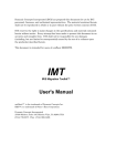

![[U4.50.01] Mot clé SOLVEUR](http://vs1.manualzilla.com/store/data/006367104_1-eebb4637bd66ac5a7564c02587699ae3-150x150.png)