1
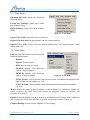
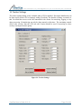
Goodrich ISR Systems ViewPoint User’s Guide v.2.1.2 June 6, 2010 Authors: Alex Barchett / Doug Miley 2621 Wasco Street / PO Box 1500 / Hood River, OR 97031 (541) 387-2120 phone / (541) 387-2030 fax www.cloudcaptech.com / [email protected] / [email protected] Cloud Cap Technology, a Goodrich Company www.cloudcaptech.com | [email protected] | Tel. +1.541.387.2120 | Fax +1.541.387.2030 Table of Contents 1 Communications Dialog ......................................................................................................... 4 Advanced Settings .......................................................................................................... 5 1.2 Server Settings ................................................................................................................ 6 1.3 Proxy Settings ................................................................................................................. 6 2 1.1 ViewPoint Overview............................................................................................................... 7 Touch Screen Control Panel ........................................................................................... 7 2.2 Primary Status Bar .......................................................................................................... 8 2.3 Playback Bar ................................................................................................................... 8 2.4 Disk Status Bar ............................................................................................................... 9 3 2.1 Main Menus ............................................................................................................................ 9 3.1 File Menu ........................................................................................................................ 9 3.2 Communications Menu................................................................................................. 10 3.3 Video Menu .................................................................................................................. 10 3.4 Gimbal Commands Menu ............................................................................................. 11 3.5 Settings Menu ............................................................................................................... 12 3.6 Display Menu................................................................................................................ 13 3.7 Tools Menu ................................................................................................................... 14 3.8 Units Menu.................................................................................................................... 14 3.9 Windows Menu............................................................................................................. 15 3.10 Help Menu .................................................................................................................... 16 4 OpenGL................................................................................................................................. 16 5 Playback Settings .................................................................................................................. 16 6 Network Video Input Settings .............................................................................................. 17 7 Camera Settings .................................................................................................................... 17 8 Gimbal Axis Settings ............................................................................................................ 19 Filter Settings ................................................................................................................ 20 8.2 Advanced Filter Settings............................................................................................... 20 9 8.1 GPS Lever Arm Settings....................................................................................................... 21 10 Tracker Settings ................................................................................................................ 22 11 Joystick Settings................................................................................................................ 23 ViewPoint User’s Guide 6-10-10 Page 2 of 48 www.cloudcaptech.com | [email protected] | Tel. +1.541.387.2120 | Fax +1.541.387.2030 12 Pilot/Stow Settings............................................................................................................ 24 13 Mosaic Settings................................................................................................................. 25 14 Download Elevation.......................................................................................................... 26 15 License Key Manager ....................................................................................................... 27 16 Plugin Manager................................................................................................................. 27 17 Export Video to File.......................................................................................................... 28 18 Gimbal Status.................................................................................................................... 29 19 Compass............................................................................................................................ 29 20 Mosaic Status .................................................................................................................... 29 21 Quick Commands.............................................................................................................. 30 22 Pan/Tilt/Zoom ................................................................................................................... 30 23 Laser Control .................................................................................................................... 31 24 Video Ground Station ....................................................................................................... 31 25 Path Track ......................................................................................................................... 32 25.1 26 Settings.......................................................................................................................... 33 Map Window .................................................................................................................... 33 26.1 Map Actions.................................................................................................................. 33 26.2 The 2D Map .................................................................................................................. 35 26.3 The 3D Map .................................................................................................................. 36 27 Map Actions Menu ........................................................................................................... 37 28 Layers................................................................................................................................ 38 29 Requesting Layers............................................................................................................. 39 30 Download Imagery............................................................................................................ 40 31 Geostamp .......................................................................................................................... 42 32 Video Interaction .............................................................................................................. 43 33 Mosaic Interaction ............................................................................................................ 43 34 Keyboard Shortcuts........................................................................................................... 44 35 Joysticks............................................................................................................................ 45 35.1 Logitech Joysticks......................................................................................................... 45 35.2 XBOX Joystick ............................................................................................................. 47 35.3 MSI Joystick ................................................................................................................. 48 ViewPoint User’s Guide 6-10-10 Page 3 of 48 www.cloudcaptech.com | [email protected] | Tel. +1.541.387.2120 | Fax +1.541.387.2030 1 Communications Dialog After the application has been launched, the communication setup dialog will appear on the screen. There are several options that the communications dialog can appear, based upon the type of connection that is selected in the top drop down box. Figure 1 - Communications Dialog Serial Direct: ViewPoint connects the gimbal using a serial port. The default option is to connect over the COM1 serial port at 57,600 bits per second. Serial Autopilot: ViewPoint communicates with the gimbal by connecting directly to an autopilot or ground station using a serial port. Network Direct: ViewPoint communicates with the gimbal by connecting to a gimbal using a network address.. Network Autopilot: ViewPoint communicates with the gimbal by connecting to an autopilot or a ground station using a network address. This address can be an IP address (for example, 127.0.0.1) or a name such as localhost. The network address can be followed by a port number such as localhost:2001. Network Pleora: ViewPoint communicates with the gimbal by connecting to a Pleora analog video IP engine. Axis Video Server: ViewPoint communicates with the gimbal by connecting to an Axis video server. Currently only video servers that support MJPEG are supported. The address of the video server must be specified as well as the Axis serial port (1 - 4) that is connected to the gimbal. ViewPoint User’s Guide 6-10-10 Page 4 of 48 www.cloudcaptech.com | [email protected] | Tel. +1.541.387.2120 | Fax +1.541.387.2030 1.1 Advanced Settings Figure 2 - Communications Dialog Advanced Settings Connection Protocol: Defines which stream the software uses on the autopilot to send and receive gimbal data. In almost all cases it makes sense just to use the Gimbal stream. In situations where more than one gimbal are hooked up to one autopilot, the other streams may be used for communication. Autopilot Connection Settings: Defines which autopilot serial number the application will communicate with. This enables the user to switch between vehicles on the network. Note: This only switches the communications stream, not the video stream. Video Source: Defines the video channel that the frame grabber will use. Note: This is not applicable for all frame grabbers, and the field will only be populated with the legal values for the frame grabber you have selected. Frame Rate: Check Auto Rate Control to let ViewPoint determine the best rate to use for processing video. Under normal circumstances this will be the rate of the video standard used (NTSC/PAL). If ViewPoint is unable to run at full rate it will reduce the rate in an attempt to keep the video as smooth as possible. Uncheck the auto rate control to take control of the video processing rate. Than select a rate as a percentage of the maximum rate for the current video standard. This may be useful when running other processes that will require additional resources. ViewPoint User’s Guide 6-10-10 Page 5 of 48 www.cloudcaptech.com | [email protected] | Tel. +1.541.387.2120 | Fax +1.541.387.2030 1.2 Server Settings The gimbal application can act as a TCP server allowing multiple clients to connect and request data. In the default mode, the application does not listen for incoming client connections. To activate the listening mode, check the Enable Network Server box and click either the OK or Apply button. To listen on a new port, update the port number and click the OK or Apply button. You can change the port only when the Enable Network Server box is checked. Changing the port terminates all connections on the current port. Figure 3 - Server Settings The following sets of data can be requested in either single requests or streaming mode: Video data in JPEG / YUV:422 Telemetry stream. 1.3 Proxy Settings Allows you to enable a proxy server for your particular internet connection. Figure 4 - Proxy Settings ViewPoint User’s Guide 6-10-10 Page 6 of 48 www.cloudcaptech.com | [email protected] | Tel. +1.541.387.2120 | Fax +1.541.387.2030 2 ViewPoint Overview The screen shown displays an overview of what ViewPoint looks like in a nominal configuration with a Bing map downloaded as a WMS image layer. Figure 5 - ViewPoint Overview 2.1 Touch Screen Control Panel The touch screen controls (Figure 6) in the video display area are for use with a touch screen panel PC. If you are using a regular PC, the touch screen controls can be activated using the mouse. The red square around a control denotes that the function is enabled. ViewPoint User’s Guide 6-10-10 Page 7 of 48 www.cloudcaptech.com | [email protected] | Tel. +1.541.387.2120 | Fax +1.541.387.2030 Figure 6 - Touch Screen Control Panel 2.2 Primary Status Bar The Primary Status Bar displays the status lights for communications, GPS, navigation, and laser control. Figure 7 - Primary Status Bar 2.3 Playback Bar The record button is disabled during playback. The playback controls the playback of video as well as telemetry data. To increase the playback speed, hold the Step 1 Frame or Step 1 Second button down. The playback speed depends on the frame rate and the disk read rate. The playback speed cannot be incremented beyond the frame rate. To view live data, switch to frame grabber by clicking on the Live button. The slider can be used to adjust the video within a 10 minute sequence. To adjust, use the buttons to the right and left of the slider. These will adjust the center location of the slider by 5 minutes. ViewPoint User’s Guide 6-10-10 Figure 8 - Playback Bar Page 8 of 48 www.cloudcaptech.com | [email protected] | Tel. +1.541.387.2120 | Fax +1.541.387.2030 2.4 Disk Status Bar The time until the disk is full does not matter in playback mode since you are not recording. Instead of the disk status the image below now shows some statistics about the current playback directory and current image being displayed. The current image time being shown can be used to correlate the image being displayed to the recorded data. The recorded data file names include an image time stamp of the first image in the file. Note that these are not GPS times, but are local computer times. Figure 9 - Disk Status Bar Description 3 Main Menus This section lists the entries in the top level menu of ViewPoint. Many of the entries are explained in more detail in the sections related to specific dialogs of ViewPoint. Figure 10 - Main Menus 3.1 File Menu Set Record / Playback Directory: Specify the directory for logging or playback depending on the current mode. Exit: Closes the application, automatically saving the current configuration. Figure 11 - File Menu ViewPoint User’s Guide 6-10-10 Page 9 of 48 www.cloudcaptech.com | [email protected] | Tel. +1.541.387.2120 | Fax +1.541.387.2030 3.2 Communications Menu Gimbal Communications: Opens the Communications Dialog. Use this dialog to change communication settings. Server Settings: Opens the Server Settings dialog. The gimbal application can act as a TCP server allowing multiple clients to connect and request data. Figure 12 - Communications Menu Proxy Settings: Opens the Proxy Settings dialog. Allows you to enable a proxy server for your particular internet connection. Display Only Mode: Sets the user interface to display only mode. In this mode no commands will be sent to the gimbal, but the user interface will continue to update the video, and the telemetry. 3.3 Video Menu Video Input Frame Grabber: In this mode, you can view any video data you have connected, you have full control of the gimbal, and you have the ability to record video and telemetry data. Set the storage location for recorded data using the Set Record/Playback command under the File menu. Figure 13 - Video Menu Disk: In this mode you can play video back from disk. During playback you cannot control the gimbal. The telemetry that you see during playback is the telemetry associated with the recorded images. Select the playback directory through the Set Record/Playback command under the File menu. This directory cannot be changed during playback. Network: In this mode you can view data from another instance of ViewPoint that is configured as a server. Once in this mode configure the network video input settings to connect to a new server. Simulation: In this mode you can view simulated video data. This option is only available with the VideoSim license key. ViewPoint User’s Guide 6-10-10 Page 10 of 48 www.cloudcaptech.com | [email protected] | Tel. +1.541.387.2120 | Fax +1.541.387.2030 Image Format YUV:Data is recorded in 16 bpp YUV:422 format. RGB: Data is recorded in 24 bpp BGR format. JPEG: Data is recorded in JPEG format. Playback Settings: Opens the Playback Settings dialog. This tool allows you to specify how you want data to be viewed based on any tracker telemetry that is available in the recorded files. It also affects data viewed in playback or network mode and affects data that is written to an AVI. Network Video Input Settings: Opens the Network Video Input Settings dialog. Adjust network settings to connect to a different server, or adjust the data rate. Sync Video: Initialize the reset sequence for the frame grabber. Save Snap-Shot: Records the image or mosaic that is currently displayed to the record/playback directory along with associated telemetry. Places an icon on the map that is displayed in playback mode. 3.4 Gimbal Commands Menu Gimbal Mode Rate: Change to rate feedback mode. Geo Point: Change to Geo Point mode. The Geo Point will be set to the current image position. Gimbal Stabilization Turn On: Enables the gimbal stabilization. Turn Off: Disables the gimbal stabilization. Figure 14 - Gimbal Commands Joystick / Keyboard Keyboard Mode - Switches to keyboard mode. If in rate mode it zeros the current rate command. Joystick Mode - Switches to joystick mode. If in rate mode it zeros the current rate command. Retract / Deploy: These commands are only applicable to systems with a deployment mechanism integrated with the gimbal. Retract: Retracts the gimbal if it is not already retracted. Deploy: Deploys the gimbal if it is not already deployed. ViewPoint User’s Guide 6-10-10 Page 11 of 48 www.cloudcaptech.com | [email protected] | Tel. +1.541.387.2120 | Fax +1.541.387.2030 Stow Gimbal: Sets the pan angle to 180 degrees, and the tilt angle to 0 degrees. Disables gimbal stabilization, and zooms the camera all the way out. If this command fails to reach the commanded position within a fixed period of time, it will timeout and the gimbal will remain at the current position. The pan and tilt angles can be customized using the Pilot/Stow Settings dialog. Pilot View: Sets the pan angle to 0 degrees, and the tilt angle to 0 degrees. Disables gimbal stabilization, and zooms the camera all the way out. If this command fails to reach the commanded position within a fixed period of time, it will timeout and the gimbal will remain at the current position. The pan and tilt angles can be customized using the Pilot/Stow Settings dialog. Switch Camera: Switches the active camera. This option is only visible if running with a dual camera system. Set Initial Heading: Enter the initial magnetic compass heading in this dialog. Providing this data to the gimbal can improve the heading estimates of the gimbal. 3.5 Settings Menu Camera Settings: Opens Camera Settings dialog. the Edit Axis Settings: Opens the Gimbal Axis Settings dialog. GPS Lever Arm Settings: Opens the GPS Lever Arm dialog. Tracker Settings: Only available when VPS is installed. Opens the Tracker Settings dialog. Figure 15 - Settings Menu Joystick Settings: Opens the dialog for setting up the joystick. Set Pilot/Stow Angles: Opens the dialog for setting the Pilot and Stow angles. Mosaic Settings: Opens the dialog for setting up the Mosaicing feature. ViewPoint User’s Guide 6-10-10 Page 12 of 48 www.cloudcaptech.com | [email protected] | Tel. +1.541.387.2120 | Fax +1.541.387.2030 3.6 Display Menu Use Native Resolution: This sets the video display size to 640 x 480. Setting this will maximize performance as no scaling will be required. Freeze Frame: Stops the video feed from updating the video display. Video and telemetry are received and processed by the application, but not displayed. Show Brackets Over Video: Displays half transparent brackets over the middle of the video stream. Figure 16 - Display Menu Deinterlacing Off: Deinterlacing to the video is off. Only the raw video is shown. Duplicate: The lines of the first field in each frame are doubled. The second field is discarded. Hybrid: This proprietary method enhances clarity by doubling the first field with smoothed lines. Blend: Both fields are blended together. Use OpenGL: Switch between OpenGL and Safe display modes. Safe mode is recommended for certain graphics cards, however in this mode the Mosaicing feature is not currently supported. ViewPoint will set this state initially based on your graphic cards. See OpenGL for more information. Pan Tilt Zoom Control: Displays the pan/tilt/zoom controls on the touch screen control panel. Zoom Control: Displays the zoom controls on the touch screen control panel. Left Hand Mode: Repositions the touch screen control panel for left-hand use. Full Screen Mode: Hides the main menu and top label bar. Click the Menu icon to display the full menu. ViewPoint User’s Guide 6-10-10 Page 13 of 48 www.cloudcaptech.com | [email protected] | Tel. +1.541.387.2120 | Fax +1.541.387.2030 3.7 Tools Menu Download Elevation: Opens the Download Elevation dialog. License Key Manager: Opens the License Key Manager dialog Plugin Manager: Opens the Plugin Manager dialog. Figure 17 - Tools Menu Export Video to File: Opens the video creation tool. Request Vibration Data: Requests gimbal data for vibration analysis. Import CSV to Path: Selects a file to be used for path tracking. This features requires a path tracker license key. 3.8 Units Menu Lat/Lon: Selects the units used for latitude and longitude measurements. Radians Degrees: decimal degrees DMS: degrees minutes seconds MGRS-8: Military Grid Reference System, 8 digit coordinate MGRS-10: Military Grid Reference System, 10 digit coordinate Figure 18 - Units Menu UTM/UPS zone: UTM (Universal Transverse Mercator) coordinates with longitude zone letter and latitude zone number e.g., 10S UTM/UPS hemi: UTM coordinates with N/S hemisphere and longitude zone number e.g., N 10 Metric: Selects the metric system of measure in which distances are kilometers, lengths are meters, velocities are meters per second, masses are kilograms, forces are Newtons, and pressures are in Pascals. English: Selects the English system of measure in which distances are nautical miles, lengths are feet, velocities are knots, mass and force are pounds, and pressure is inches of mercury. Compass Heading: Selects between Magnetic or True heading. ViewPoint User’s Guide 6-10-10 Page 14 of 48 www.cloudcaptech.com | [email protected] | Tel. +1.541.387.2120 | Fax +1.541.387.2030 3.9 Windows Menu Status and control options can be accessed from these menus. Check the Map Window box to display or hide the main map window. Status Gimbal Status: A dockable window that displays gimbal and image position information. Gimbal Telemetry: A dockable window that displays a text output of telemetry information for the gimbal. Compass: Displays the gimbal and vehicle heading. See Compass for more information. Primary Status Bar: Displays the status lights for communications, GPS, navigation, and laser control. See ViewPoint Overview for more information. Disk Status Bar: Displays information on the current disk status. See ViewPoint Overview for more information. Mosaic Status: Displays information on the current Mosaic status. Figure 19 - Windows Status Menu Control Quick Commands: Opens the Quick Commands window for the gimbal. Pan Tilt Control: Display the Pan/Tilt/Zoom controls in a separate window. Laser Control: Displays the Laser Controls in a dockable window. Video Ground Station: Displays the Video Ground Station control in a dockable window. Figure 20 - Windows Control Menu Playback Bar: Displays the buttons used to control the playback and recording of video. See ViewPoint Overview for more information. Path Track: Displays the Path Track window. ViewPoint User’s Guide 6-10-10 Page 15 of 48 www.cloudcaptech.com | [email protected] | Tel. +1.541.387.2120 | Fax +1.541.387.2030 3.10 Help Menu Contents: Displays the contents of the Help menu. Gimbal Version: Display the gimbal firmware version, firmware build date, a description of the cameras, the gimbal serial number, and a vehicle serial number if connected through an autopilot. Since there can be more than one camera in the system the active camera will be highlighted. Figure 21 - Help Menu About: Display the Gimbal Control Application software version and build date. About QT: Provides information on the version of QT used in ViewPoint. 4 OpenGL ViewPoint now uses OpenGL for video display. Interaction between OpenGL and ViewPoint can result in unstable behavior with some graphics cards. ViewPoint allows the user to switch between OpenGL and Safe mode. When ViewPoint is started for the first time it identifies the graphics cards and places your display in the best mode (based on the current graphics cards information we have available). You can change modes, but you will always be alerted when you are leaving Safe mode. If you have a card that has been identified as unstable, ViewPoint will alert you that switching to OpenGL mode is not recommend. Currently Safe mode does not support real-time mosaicing. Real-time mosaicing can only be used in OpenGL mode. If you exhibit unstable behavior in ViewPoint please switch to Safe mode and contact us. 5 Playback Settings This tool allows you to specify how you want data to be viewed based on any tracker telemetry that is available in the recorded files. It also affects data viewed in playback or network mode., and affects data that is written to an AVI. Select Show Raw Video to display the raw video without any additional processing. Select Show Processed Video to display the video with tracker offsets that were recorded during flight. Select Show Track Box to display a box around the region that was tracked during flight. Select Center Track to center the region that was tracked during flight. ViewPoint User’s Guide 6-10-10 Figure 22 - Playback Settings Page 16 of 48 www.cloudcaptech.com | [email protected] | Tel. +1.541.387.2120 | Fax +1.541.387.2030 6 Network Video Input Settings ViewPoint can receive both video and telemetry over the network from another instance of ViewPoint. Once in network mode the network settings can be adjusted to connect to a different server, or adjust the data rate. Because the ability to stream data in real-time is greatly dependent on the speed of the network, a Half Rate option is available to reduce the amount of network traffic. In this mode the frame rate at the client end will not exceed 15 frames per second. Figure 23 - Network Video Input Settings 7 Camera Settings When this dialog is opened (Figure 24), the application synchronizes with the gimbal. When the application and gimbal are synchronized, the values are displayed and the "Settings in Sync" label turns green. To change the gimbal settings, modify the values in the dialog and press "Send Updates". The application updates the gimbal and confirms the changes. While the application and gimbal are out of sync, the "Settings in Sync" label is red. When the gimbal settings are altered and confirmed, the "Settings in Sync" label returns to the green state. Camera ID: Allows you to change the "active" camera When changing the active camera all of the other settings on this dialog will be applied to the new active camera. To simply change the active camera without changing the camera settings use the "Switch Camera" menu option, or the "Toggle Camera" command from the joystick. Field of View Use Zoom Ratio: Allows you to enter a value between 1 and the maximum value for the camera. Use degrees: Allows you to enter a fixed zoom value in degrees. The limits are camera dependent. Focus Manual Focus: Allows you to enter a fixed value in mm for the focus. This limits are camera dependent. Infinite Focus: Allows you to set the focus for an unlimited distance. Focus on Current: Enables the focus on the current view. Auto Focus: Lets the camera automatically adjust the focus. ViewPoint User’s Guide 6-10-10 Page 17 of 48 www.cloudcaptech.com | [email protected] | Tel. +1.541.387.2120 | Fax +1.541.387.2030 Exposure Full Auto: Lets the camera automatically adjust the exposure. Shutter Priority: Allows you to set the shutter speed manually. Bright: Allows the user to set the brightness, which will cause the camera to adjust the exposure appropriately. Shutter Speed Shutter Speed (sec): This value can only be set when the exposure mode is set to shutter priority. Brightness Brightness Settings: This value can only be set when the exposure mode is set to bright. Figure 24 - Camera Settings Image Polarity White Hot: Allows the user to set white hot mode. Black Hot: Allows the user to set black hot mode. If not using an IR camera this may just show a negative image. Video Output High Def: Allows the user to output high definition video (Sony FCB-H10 only). PAL: Allows the user to output PAL video (Sony FCB-H10 only). Image Stabilization: Allows the user to output stabilized imagery (FCB-980S only). Black and White: Allows the user to put the camera in black and white mode. This is done by removing the IR cut filter. Image Title: Allows the user to turn the image title feature on or off. The image title is data printed on the video by the camera. Perform Lens Initialization: Allows the user to request a non-uniformity correction for IR cameras, or a lens initialization for the Sony zoom cameras. ViewPoint User’s Guide 6-10-10 Page 18 of 48 www.cloudcaptech.com | [email protected] | Tel. +1.541.387.2120 | Fax +1.541.387.2030 8 Gimbal Axis Settings When this dialog is opened, the application synchronizes with the gimbal. When the application and gimbal are synchronized, the values are displayed and the Settings in Sync label turns green. To change the gimbal settings, modify the values in the dialog and click Send Updates. The application updates the gimbal and confirms the changes. While the application and gimbal are out of sync, the Settings in Sync label is red. When the gimbal settings are altered and confirmed, the Settings in Sync label returns to the green state. Figure 25 - Gimbal Axis Settings No Go Center: Defines the center of a region within which the system cannot go. No Go Range: Defines the area around the no go center within which the system cannot go. If the no go range is set to 0.0 the system is free spinning. Max Rate: Defines the maximum rate of motion of the gimbal in degrees per second. Max Accel: Defines the maximum acceleration of the gimbal in degrees per second squared. Position Gain: - Defines the position feedback gain in units of degrees per second per degree. Changing the rate, acceleration, or gain will affect gimbal performance. The default values can be restored by pressing the reset button. ViewPoint User’s Guide 6-10-10 Page 19 of 48 www.cloudcaptech.com | [email protected] | Tel. +1.541.387.2120 | Fax +1.541.387.2030 8.1 Filter Settings The filter settings allow the user to control the inertial sensor filters. Cutoff Frequency: Lower values reduce noise, higher values increase stabilization bandwidth. Deadband: Increasing this value reduces the effects of gyro noise and bias error at the expense of stabilization accuracy. Figure 26 - Filter Settings 8.2 Advanced Filter Settings Reference Camera Alignment Procedure: The alignment procedure allows the user to remove any errors between the gimbal position measured by the encoders and the cameras bore-sight axis. The alignment can vary as a function of optical zoom which is why we measure it in two locations. Updating the alignment cannot be undone. If performed incorrectly it will affect gimbal performance! 1. Start the alignment procedure by clicking the Start Alignment button. 2. Zero the alignment. This will ensure that the new alignment angles are an offset from zero and not from the previous settings in the gimbal. 3. Use the Capture 1 and Capture 2 buttons to capture the current pan, tilt, and zoom. 4. Click the Send Updates button to send these values to the gimbal. 5. If the camera does not have analog zoom, check the Use Alignment 1 for Alignment 2 checkbox to set the two alignment numbers equal. 6. Once alignment values have been sent to the Gimbal either exit the dialog or click the Cancel Alignment button to exit the alignment process. Figure 27 - Gimbal Advanced Axis Settings ViewPoint User’s Guide 6-10-10 Page 20 of 48 www.cloudcaptech.com | [email protected] | Tel. +1.541.387.2120 | Fax +1.541.387.2030 If the dialog is closed or the Cancel Alignment button is clicked, the process is canceled. If the Send Updates button has not been clicked, no values will be sent to the gimbal. The Zoom, Digital Zoom, and Position Cmd. tools at the bottom of the dialog allow for easier control of the camera zoom and position without leaving the dialog. Secondary Camera Alignment Procedure: The alignment of the second camera takes into account an offset in alignment from the first camera. 1. Start the alignment procedure by clicking the Start Alignment button. 2. Zero the alignment. This will ensure that the new alignment angles are an offset from zero and not from the previous settings in the gimbal. 3. Line up a reference target with the reference camera and click the Capture Ref button. 4. Click the Switch Camera button to switch to the secondary camera. 5. Line up the same target in the center of the secondary camera, and then click the Capture 1 button. 6. If the camera has an analog zoom, zoom the camera and click the Capture 2 button. If the camera does not have an analog zoom, use then check the Use Alignment 1 for Alignment 2 checkbox to set the two alignment numbers to the same value. A delta between the two measurements is calculated and stored in the alignment column. 7. Send the values to the gimbal by clicking the Send Updates button. To use a custom alignment enter the values in the alignment column and click the Send Updates button. Once alignment values have been sent to the Gimbal either exit the dialog or click the Cancel Alignment button to exit the alignment process. 9 GPS Lever Arm Settings Allows the user to set the distance from the IMU of the gimbal to the GPS antenna. Distances are set with respect to the gimbal coordinate system. Figure 28 - GPS Lever Arm Settings ViewPoint User’s Guide 6-10-10 Page 21 of 48 www.cloudcaptech.com | [email protected] | Tel. +1.541.387.2120 | Fax +1.541.387.2030 10 Tracker Settings The tracker settings dialog is only available when a VPS is installed. Electronic Stabilization can be done locally on the VPS or remotely within ViewPoint. The benefits of doing it remotely is that ViewPoint has access to the full unmodified video frame for mosaicing, logging, or any other processing. Deinterlacing can only be done remotely at this time. The remaining controls affect video overlays that the VPS can add. Caution should be used if mosaicing as these overlays can impact mosaic quality. Figure 29 - Tracker Settings ViewPoint User’s Guide 6-10-10 Page 22 of 48 www.cloudcaptech.com | [email protected] | Tel. +1.541.387.2120 | Fax +1.541.387.2030 11 Joystick Settings Simple Settings Because each user and each mission demands a different level of control, many of the basic joystick features are configurable. These settings are stored so that each time you start the application your most recent settings are used. To implement your changes, click OK or Apply. Joystick Rate Mode / Advanced Rate Mode: Define the degree of adjustment applied to the current rate with joystick movement. Fine Mode: Used for precise control of the rate settings. The example above shows a fine mode setting of 30%, which means that if the joystick is moved all the way to one side, the rate will be updated by 30% of the field of view every 10Hz. Figure 30 - Simple Joystick Settings Coarse Mode: Used for large adjustments of the rate settings. The example above shows a coarse mode setting of 80%, which means that if the joystick is moved all the way to one side, the rate command will be updated by 80% of the field of view every 10Hz. Joystick Zoom Mode / Advanced Zoom Mode: Define the degree of adjustment applied to the current zoom command. Fine Zoom: Used for small zoom adjustments. The example above shows a fine setting of 10%, which means for each fine joystick zoom button press the zoom will be adjusted by 10% of the current setting. Coarse Zoom: Used for large zoom adjustments. The example above shows a coarse setting of 50%, which means for each coarse joystick zoom button press the zoom will be adjusted by 50% of the current setting. Send Command Every: Holding the zoom buttons down will cause the command to be sent over and over. The example below shows the default rate of 500 msec. Setting this number too small can make it difficult to hit the button once without sending multiple commands. It can also cause the camera to ignore the commands until the joystick button is released. Cursor Control Settings: To enable the use of the joystick to control the cursor, check the Enable Cursor Control box and click the OK or Apply button. You control the responsiveness of the cursor movement with the Slow to Fast slider. ViewPoint User’s Guide 6-10-10 Page 23 of 48 www.cloudcaptech.com | [email protected] | Tel. +1.541.387.2120 | Fax +1.541.387.2030 Advanced The advanced settings allows the user to select one of seven default joystick configurations, or create a custom configuration. The table above shows which buttons are mapped to which actions for the currently selected setup. For a graphical view of the button mappings for the default configurations see Joysticks. For a custom configuration select the button/ctrl you want to map to a given action. If the joystick is not labeled, you can often determine the button numbers from the Windows Control Panel - Game Controllers. The ability to negate the pan or tilt axis controls is only supported under the custom configuration. Figure 31 -Advanced Joystick Settings 12 Pilot/Stow Settings The gimbal application has support for two saved views: pilot and stow. These saved views can be set to point to any pan and tilt angles using this dialog. If you click Apply or OK, these settings are stored so that next time you start the application your new settings are used. Is is important to ensure that the angles are not in an area that the gimbal cannot reach due to the Axis Settings. ViewPoint User’s Guide 6-10-10 Figure 32 - Pitot / Stow Settings Page 24 of 48 www.cloudcaptech.com | [email protected] | Tel. +1.541.387.2120 | Fax +1.541.387.2030 13 Mosaic Settings The mosaic settings dialog is only available when a valid Mosaic key is entered. Figure 33 - Mosaic Settings Image Cropping: Because there can often be black lines around the edge of video, stabilization artifacts, or text, this feature allows you to crop off a little bit of each image before mosaicing that results in a cleaner final mosaic. Always Generate Mosaic: When this is checked the mosaic process is running even when you are in standard view. As a result when you switch to mosaic view it won't be starting a mosaic from scratch. WARNING: Enabling this feature requires additional resources and can result in reduced frame rate in standard view. Play Recorded Mosaic: If you recorded data while you were running the mosaic process checking this allows you to play it back exactly as recorded. Typically this will not provide much benefit over just letting the mosaic be recreated during playback, however it may be useful in some circumstances and will require fewer resources during playback. Texture Memory: The amount of history that can be retained in the mosaic is determined by the video card quality. Because some video cards do not perform as well as others this control allows users to limit the amount of history that the mosaic process will keep while allowing other users with higher end cards to retain longer histories. If the frame rate suddenly drops off while mosaicking or is not consistent lower this number until the frame rate stabilizes. In some systems if this number is to high the frame rate can suddenly go from 30 FPS to 0.5 FPS or less. ViewPoint User’s Guide 6-10-10 Page 25 of 48 www.cloudcaptech.com | [email protected] | Tel. +1.541.387.2120 | Fax +1.541.387.2030 14 Download Elevation Elevation data can be retrieved from a Web Mapping Service (WMS) and stored locally in a native format. This tool requires an active internet connection. If an internet connection will not be available during the mission, this tool can be used to download the required elevation data prior to the mission. To request data simply fill in a latitude and longitude and click the Get Data button. During the flight, if data doesn't exist the application automatically tries to access the internet to download elevation data. Figure 34 - Download Elevation Check Coverage: This application can be used to determine what data currently exists. To check the coverage simply fill in a latitude and longitude and click the Get Data button. When complete this process will notify you what percent of the requested data currently exists. At this time you can determine if you need to go download more elevation data. Current File Status Bar: Displays the status of the current file that is being downloaded Overall Status Bar: Displays the status of the download process as a whole. ViewPoint User’s Guide 6-10-10 Page 26 of 48 www.cloudcaptech.com | [email protected] | Tel. +1.541.387.2120 | Fax +1.541.387.2030 15 License Key Manager This tool allows you to manager multiple license keys for a single user. Enter a user name and a key and press the Add Key button to add a new key. Once the key is added only the key information is shown. Figure 35 - License Key Manager To remove a key, highlight the key information, and then press the Remove Key button. To show the actual key, highlight the key information and press the Show Key button. 16 Plugin Manager This tool allows you to manage the plugins. Use the Load Plugin button to load a specific plugin. The load function is unique to each plugin, but usually this will open windows, potentially start threads, etc. Use the Unload Plugin button to unload a specific plugin. The unload function is unique to each plugin, but usually this will close windows, stop threads, etc. Check the box under the Startup column to force a plugin to be loaded automatically the next time the application starts. Check the box under the Disable Send column to prohibit the plugin from sending commands to the Gimbal. Check the Disable All Plugins From Sending Commands checkbox to prohibit all plugins from sending commands to the gimbal. This may be useful if you want to quickly make sure that only ViewPoint has control. Use the About button to get more information on the plugin. Figure 36 - Plugin Manager ViewPoint User’s Guide 6-10-10 Page 27 of 48 www.cloudcaptech.com | [email protected] | Tel. +1.541.387.2120 | Fax +1.541.387.2030 17 Export Video to File This tool allows you to create an AVI video file from previously recorded image and telemetry data. The Input Directory specifies the location of your saved image and telemetry data. The Output Filename specifies the name and location of the AVI file you are going to create. Use the Start Time and End Time sliders to create a video file that is a subset of your recorded data. As you adjust the sliders the Estimated Time Remaining value will be updated. This value shows you a rough estimate of the time to finish creating the video and will continue to be updated as the video is being generated. Figure 37 - Export Video to File Check the View Video While Recording box if you would like the video to be displayed in the main application window as the video is being created. This will slow down the process of creating a video. The video displayed will not be real-time and may appear either slow or fast depending on the machine you are running this process on. The AVI file can be created from raw video, or if a tracker was used, it can be created with tracking regions highlighted as well as tracker offsets incorporated to stabilize the output. To adjust these settings click the Edit Playback Settings button. Once the input directory, output filename, start time, and end times are setup click the Create Video button to start the video creation process. While the video is being created you can stop it at anytime with the Stop button. ViewPoint User’s Guide 6-10-10 Page 28 of 48 www.cloudcaptech.com | [email protected] | Tel. +1.541.387.2120 | Fax +1.541.387.2030 18 Gimbal Status The Gimbal Status window displays the current gimbal position. Displays the image position of the center of the image as calculated by ViewPoint. Figure 38 - Gimbal Status 19 Compass Camera Velocity Heading: Indicated by the black arrow. The actual value to two decimal places is shown above the compass. Camera Heading: Indicated by the red arrow. The actual value to two decimal places is shown below the compass. Camera Pitch: Indicated by the red rectangle on the right side of the compass. The range for the camera pitch is +/90.0 degrees shown by the blue line. Use the Units menu option to toggle between true and magnetic heading. A "T" following the heading indicates that it is a true heading that is being displayed, and an "M" indicates magnetic heading. Figure 39 - Compass 20 Mosaic Status The Mosaic Status window provides the state of the mosaic algorithms. Figure 40 - Mosaic Status ViewPoint User’s Guide 6-10-10 Page 29 of 48 www.cloudcaptech.com | [email protected] | Tel. +1.541.387.2120 | Fax +1.541.387.2030 21 Quick Commands Pilot: Change to Pilot View (0 degree pan, 0 degree tilt). Disables gimbal stabilization. Zooms the camera all the way out. Geo Point: Change to Geo Point mode. This sets the new Geo Point to the current image location (as long as it can be determined). Deploy: Deploys the gimbal if it is not deployed. This is only applicable in systems with a deployment mechanism integrated with the gimbal. Figure 41 - Quick Commands Stow: Stows the gimbal (180 degree pan, 0 degree tilt - or user configured values). Disables gimbal stabilization. Zooms the camera all the way out. Rate: Change to rate mode, setting the pan and tilt rates to 0.0 deg/sec. Enables gimbal stabilization. Retract: Retracts the gimbal if it is not retracted. This is only applicable in systems with a deployment mechanism integrated with the gimbal. Switch Camera: For use with dual Gimbal cameras. Allows the user to switch camera views over a single video link. 22 Pan/Tilt/Zoom The pan-tilt-zoom buttons continue to send commands at regular intervals as long as you hold down the button. The zoom can be set to a specific zoom level using the manual zoom field. Enter a value in the Zoom field. Click Enter on your keyboard to send the command. In Rate mode the arrows adjust the current pan or tilt rate by 5% of the current field of view per second. The stop button zeros the rate command. The home button zeros the pan and tilt position angle commands. In Geo Point mode, the arrows do not affect the Geo Point. Figure 42 - Pan Tilt Zoom Controls Increases the zoom level by one step. Decreases the zoom level by one step. ViewPoint User’s Guide 6-10-10 Page 30 of 48 www.cloudcaptech.com | [email protected] | Tel. +1.541.387.2120 | Fax +1.541.387.2030 23 Laser Control Laser controls only appear for lasers installed in the gimbal. If in playback or client mode the controls will only appear if the data was captured from a system with lasers installed. The laser can be in one of four states: Off: Power is not being applied to the laser. Armed: The laser is armed and ready to fire but is currently at 0 percent power. On: The laser is armed and powered at greater than 0 percent. Power Limited: The gimbal is unable to apply the user requested power level to the laser. Figure 43 - Laser Control 24 Video Ground Station Antenna Pointer: The azimuth offset is used to account for differences between the zero of the antenna pointer and true North. After changing the value the Send Updates buttons must be pressed for this to be sent to the ground station. If the user wishes to have direct control of the antenna pointer they can check the Manual Override checkbox. When this is checked the blue triangles on the compass can be used to adjust the pan and tilt angles of the antenna pointer. Note: the commands are not sent until you are done moving the blue triangles. The compass shows the commanded (blue) and actual (red) pan and tilt angles of the antenna pointer. The inner circle represents the tilt angle, and the outer circle represents the pan angle. Figure 44 - Video Ground Station ViewPoint User’s Guide 6-10-10 Page 31 of 48 www.cloudcaptech.com | [email protected] | Tel. +1.541.387.2120 | Fax +1.541.387.2030 Radio Settings: The video ground station radio setting can be adjusted using this dialog. Note that when adjusting the settings the radio must be temporarily taken offline which will result in a short loss of communications. To change the radio settings, modify the values in the dialog and click Send Updates. The application updates the settings and confirms the changes. While the application and gimbal are out of sync, the Settings in Sync label is red. When the radio settings are altered and confirmed, the Settings in Sync label returns to the green state. GPS: This shows the current GPS state of the video ground station. 25 Path Track Start Tracking: Begins tracking the path at the point closest to the gimbal. Stop Tracking: Stops following the path and puts the gimbal in rate mode. Load Path: Loads a series of points from a comma-separated-value (csv) file to the local path. The format expected is [Latitude in Degrees], [Longitude in Degrees], e.g.: 45.680461796,-121.5054741 45.680191149,-121.50538614 45.679568527,-121.50553144 Figure 45 - Path Track If loaded successfully, the points will show up on the map as a series of gray points and lines: Figure 46 - Path Track on Map Send Path: Sends the local path to the gimbal. A progress dialog showing the points sent will display. Once all points have been sent, the remote path will show up on the map as a series of red points and lines: Request Path: Downlinks path points from the gimbal to the map. ViewPoint User’s Guide 6-10-10 Page 32 of 48 www.cloudcaptech.com | [email protected] | Tel. +1.541.387.2120 | Fax +1.541.387.2030 25.1 Settings Max velocity: The maximum velocity along the path when tracking. This value is relative to the vehicle's velocity. Limits how quickly the path tracker will "catch up" if it falls behind. Default value is 50 m/s. Active range: Indicates to the gimbal when to track along the path. When the distance from the gimbal to the path is greater than this value, the tracker's position on the path will remain fixed. Default value is 3000 m. Look ahead: Offsets how far ahead of the closest point on the path the tracker will look. Default value is 200 m. Figure 47 - Path Track Settings Step Mode: Enables or disables Step-Stare modes. These modes will update the position on the path in discrete distance/time intervals. Useful when the camera is sensitive to motion blur. The following modes are supported: Fixed distance: Moves a given distance along the path at each step. Fixed Time: Stares at each step for a given amount of time. Step Distance: Sets the fixed distance interval to use when in Step Mode with Fixed Distance. Default is 25 m. Step Time: Sets the fixed time interval to use when in Step Mode with Fixed Time. Default is 500 ms. 26 Map Window 26.1 Map Actions At the top of the map is a map actions toolbar. It can be turned off but not moved. Click the lock icon to lock the map in place when the Map Window is not docked. Interchange the video and map display. Zoom in or out on the map. Hold a button down to do a continuous zoom. ViewPoint User’s Guide 6-10-10 Page 33 of 48 www.cloudcaptech.com | [email protected] | Tel. +1.541.387.2120 | Fax +1.541.387.2030 Pans the map left, right, up, or down. Arrows are disabled when map is in Follow Active Aircraft mode. Hold a button down to pan continuously. Allows you to go to a Lat/Lon position, place or layer on the map. Places the gimbal in the center of the map at all times. This can be useful for determining current location on the map. It is also operationally useful during missions. Places the sensor footprint (center of image location) in the center of the map at all times. It is operationally useful during missions in determining the position on the ground where the video is being captured. Follows line of sight. Centers the map to look down the line of sight of the gimbal. The map rotates relative to the sensor footprint. For best results, use in conjunction with 3D Map Mode. Aircraft heading up. Centers the map on the gimbal position. Moves the map in the same direction as the aircraft is traveling. For best results, use in conjunction with 3D Map Mode. Enables/Disables the video on map feature. A valid license is required to enable this feature. Enables or disables the Map Layers window. The Map Layer window is a dockable window for selecting layers that are displayed on the map. Selects 2-D or 3-D map modes. Selects the normal mouse mode for the map. In the normal mode, the left and right mouse buttons can be used to pan and zoom the map, change the 3-D map orientation, invoke context menus. Selects the ruler mode for the map. The ruler mode allows the left button of the mouse to click and measure distance and bearings between any two points on the map. ViewPoint User’s Guide 6-10-10 Page 34 of 48 www.cloudcaptech.com | [email protected] | Tel. +1.541.387.2120 | Fax +1.541.387.2030 26.2 The 2D Map The two dimensional view of the map is a top down, North up view of the map and contains no elevation information. The geo referenced image that makes up the map was downloaded by ViewPoint as a WMS image layer. Figure 48 - The 2D Map ViewPoint User’s Guide 6-10-10 Page 35 of 48 www.cloudcaptech.com | [email protected] | Tel. +1.541.387.2120 | Fax +1.541.387.2030 26.3 The 3D Map The three dimensional view of the map is shown from an oblique view that was oriented using the mouse. It is important to realize that this is not restricted to any cardinal direction. Notice the terrain in the background. ViewPoint automatically downloads elevation information (typically from SRTM sources–shuttle radar topography mission) and warps the map imagery to fit over the terrain shape. Caution must be used when interpreting position information in 3-D mode since it is difficult to precisely visualize the gimbal position. Both the 2-D and 3-D versions of the map give important information at the bottom of the screen. The Lat and Lon numbers give the latitude and longitude of the mouse pointer over the map. The Elev number is the elevation of the terrain under the mouse pointer. Figure 49 - The 3D Map ViewPoint User’s Guide 6-10-10 Page 36 of 48 www.cloudcaptech.com | [email protected] | Tel. +1.541.387.2120 | Fax +1.541.387.2030 27 Map Actions Menu The map actions menu is invoked by right clicking anywhere in the map. Do not move the mouse when right clicking in the map. If the mouse is moving, the right click is interpreted as a zoom command. Follow Gimbal: See Map Window. Follow Payload Footprint: See Map Window. Follow Line of Sight: See Map Window. Follow Heading Up: See Map Window. Set Geo Point: Change to Geo Point mode. This sets the new Geo Point to the current image location as long as it can be determined. Show Image Pos. Indicator: Shows an indicator at the image position calculated by ViewPoint. Show Log Tags: Shows information captured in a logfile on the map. Set Sensor Footprint Color: Sets the sensor footprint color. Set FOV Line Length: Sets the length of the line used to compute the field of view terrain intersection in km. Show Video On Map: Enables/Disables the video on map feature. A valid license is required to enable this feature. Zoom In Here: Zooms the map in at the location clicked. Zoom Out: Zooms the map out. Figure 50 - Map Actions Menu Center Map Here: Moves the map to center it at the location of the click. Reset Map Position: Returns the map to its default position and zoom. Layers: Enables or disable the Map Layers window. Show Compass: Displays or hides the compass in the Map window. ViewPoint User’s Guide 6-10-10 Page 37 of 48 www.cloudcaptech.com | [email protected] | Tel. +1.541.387.2120 | Fax +1.541.387.2030 Download Imagery: Provides a method for downloading WMS map information for any map layers on the map. The downloaded data is cached so that the map can be used later when an internet connection is not available. Download Elevation: Displays or hides the Download Elevation dialog. Import Point File to Interest Points: Imports a FalconView local point file (*.lpt) to ViewPoint. Displays icons/text on the map as they appear in FalconView. Import Drawing File: Imports a FalconView drawing file (*.drw) to ViewPoint. Renders shapes on the map as they appear in FalconView. Import Drawing File to Airspace: Imports a FalconView drawing file (*.drw) to gimbal as an airspace boundary. 28 Map Layers Map Layers is a dockable window for selecting layers that are displayed on the map. Each layer has its own subcategory. To enable or disable a layer, click the check box next to the layer. To remove a layer completely, from the map and layer list, select it, and then click the Remove Selected button. To go to a image layer you have added to the map, right click on the image layer and select View on Map. Elevation Layer: Elevation data is used to provide the three dimensional shape to the map imagery. There are two types of elevation data: DTED data (typically provided on disk) and SRTM (shuttle radar topography mission) data. SRTM data is typically loaded automatically from online sources. Enabling or disabling an elevation layer causes the map to re-render the entire scene. Figure 51 - Map Layer Window Local Imagery Layer: Local imagery is a raster or vector map layer that only exists locally, i.e. on the hard drive. WMS Imagery Layer: This imagery data is downloaded automatically from online sources specified by the user. ViewPoint User’s Guide 6-10-10 Page 38 of 48 www.cloudcaptech.com | [email protected] | Tel. +1.541.387.2120 | Fax +1.541.387.2030 29 Requesting Layers 1. Click the map layer icon to open the Map Layers window. 2. Click Add » WMS. This opens the Add WMS/Internet Layer(s) dialog. 3. Select which server you would like to get data from by clicking the Server radio button. 4. Choose a server from the list in the drop-down box. You can enter your own server request if you want to query a server that is not in the list. 5. The Add WMS / Internet Layer(s) window displays the layers that are available from that server. Select a layer and click the Add Layer button. 6. In the Style drop down box you have the option to select a type of style that the map layer is displayed in. If you are using the Bing map layer you MUST choose a style type to successfully add this layer. Typically "Aerial with Labels" is the best choice.. 7. You can repeat the above process to add more layers. Once the WMS layers are added, you will see them in the Map Layers window under Web Imagery. Toggle their visibility by checking the box next to the layer name just like any other layer. Change the ordering of the layers by dragging and dropping them. Figure 52 - Add WMS/Internet Layer Dialog ViewPoint User’s Guide 6-10-10 Page 39 of 48 www.cloudcaptech.com | [email protected] | Tel. +1.541.387.2120 | Fax +1.541.387.2030 30 Download Imagery Data is saved to your computer's user directory under "Cloud Cap/WMSCACHE". Similar to C:\Users\[your username]\Cloud Cap\WMSCACHE. 1. Right click the map and choose the Download Imagery. The Download Imagery dialog lets you retrieve data for a given area from any WMS layers that have been added. The area is specified as a center point and a range (diameter), the initial values match the current view of the map 2. Choose what resolution of data you want using the Resolution slider. Lower resolution will result in less files being downloaded, but will not request images for smaller scales. Higher resolution downloads more files but will request images down for smaller scales. 3. Choose the layers you would like to download data from by checking the box next to each one. Any WMS layer already added to the software will appear in the Layers To Download list. 4. Click the Get Data button. Figure 53 - Download Imagery ViewPoint User’s Guide 6-10-10 Page 40 of 48 www.cloudcaptech.com | [email protected] | Tel. +1.541.387.2120 | Fax +1.541.387.2030 Adding Cached Data If you have downloaded imagery from a WMS server, but have removed the layer from the map using the Layers dialog, the imagery is not deleted. The data still exists in the WMS Cache directory. To return a WMS layer: 1. Click the map layer icon to open the Map Layers window. 2. Click Add » WMS. This opens the Add WMS/Internet Layer(s) dialog. 3. Check the Cached radio button. The combo box will contain a list of all the existing data that is available in your WMS Cache. 4. Check the box next to the cached layer to generate the server request. 5. Click the Add Layer button. Figure 54 - Adding Cached Data ViewPoint User’s Guide 6-10-10 Page 41 of 48 www.cloudcaptech.com | [email protected] | Tel. +1.541.387.2120 | Fax +1.541.387.2030 31 Geostamp The geostamp functionality allows the user to mark the map in real time or in replay mode. Wherever the map is marked it is also accompanied by a text box that includes the time of day when the geostamp was created. There are 6 types of geostamps. The first five are numbered 1 through 5. They are created by using the F1 through F5 function keys on the keyboard. Additionally, there is also an image geostamp created by pressing the “I” key on the keyboard. All geostamps on the map are right-clickable. The context menu allows the user to do the following: Figure 55 - Geostamp on Map View the image position Edit the text box Change the color of a specific geostamp View the image that was taken at the time the geostamp was created Jump to the time in the video when that geostamp was created (start the video from that geostamp) Image geostamps also add an image on the map that can be toggled on or off from the Map Layers dialog, under Local imagery > Raster. Geostamps are saved in an XML format file in the same directory as the video. When switching directories, the existing geostamps are loaded and displayed on the map. Geostamp images are saved in the F1 though F5 folders in the video directory. Type 1 and type 2 geostamps may also be configured to be triggered by the joystick Figure 56 - Geostamp Type and Color Legend ViewPoint User’s Guide 6-10-10 Page 42 of 48 www.cloudcaptech.com | [email protected] | Tel. +1.541.387.2120 | Fax +1.541.387.2030 32 Video Interaction Clicking on the display will produce a different result depending on which mode you are in. In Rate mode, an offset to the current pan and tilt angles is sent to the camera. For example, clicking on the van in the video image centers the van in the image. The current command rate is maintained, depending on the command rate, the van may not stay in the center of the video frame very long. This provides a one-time adjustment and does not lock on the selected position or target. In Geo Point mode, the Geo Point will be set to the current image position. Figure 57 - Video Interaction 33 Mosaic Interaction Interaction with the mosaic can be done through the mouse, touch screen, or the mosaic toolbar. In live mode operation, the current video frame is shown untransformed and highlighted by red corners as shown in the image on the left. In this mode the current frame is being kept in view at all times. In review mode, any image can become the non transformed image. The current image is no longer required to be kept in view. In review mode, the current frame is shown with red corners. The user can quickly transition from review to live mode by clicking the Live Video button on the toolbar. To enter the review mode, adjust the review slider or pan back in time to view the older data. Track initiation can only be done in live mode. Figure 58 - Mosaicing Interaction ViewPoint User’s Guide 6-10-10 Page 43 of 48 www.cloudcaptech.com | [email protected] | Tel. +1.541.387.2120 | Fax +1.541.387.2030 Click the Mosaic button on the touch screen control panel to enable the Mosaic control panel. Zoom in or out the mosaic. This doesn't impact the camera zoom. Hold a button down to do a continuous zoom. Zooming can also be done with the mouse scroll wheel. Clear Mosaic. Return to live video. Camera control on or off state. The user can offset the camera by clicking on the mosaic as long as the Camera Control State indicator is green. If this indicator is red, the transformation from the current frame to the users view can no longer be calculated. Review old data slider. 34 Keyboard Shortcuts Up Arrow: In Rate mode increase the current tilt rate command by 5% of a field of view per second. In Geo Point mode this will have no affect. Down Arrow: In Rate mode decrease the current tilt rate command by 5% of a field of view per second. In Geo Point mode this will have no affect. Right Arrow: In Rate mode increase the current pan rate command by 5% of a field of view per second. In Geo Point mode this will have no affect. Left Arrow: In Rate mode decrease the current pan rate command by 5% of a field of view per second. In Geo Point mode this will have no affect. R: Change to rate mode, setting the pan and tilt rates to 0.0 deg/sec. This will also enable gimbal stabilization. T: Change to Geo Point mode. This sets the new Geo Point to the current image location as long as it can be determined. P: Change to Pilot View (0 degree pan, 0 degree tilt). Disables gimbal stabilization, and zooms the camera all the way out. S: Stows the gimbal (180 degree pan, 0 degree tilt). Disables gimbal stabilization, and zooms the camera all the way out. ViewPoint User’s Guide 6-10-10 Page 44 of 48 www.cloudcaptech.com | [email protected] | Tel. +1.541.387.2120 | Fax +1.541.387.2030 I: Record the current image. This will save the displayed image as a bitmap and store the associated telemetry in an XML file. Ctrl-S: Turn on the gimbal stabilization. Ctrl-Shift-S: Turn off the gimbal stabilization. Ctrl-Z: Send the zero gyro command. The gimbal must not be moving when you zero out the gimbal. Ctrl-J: Change to joystick mode. If you are working in Rate mode, this selection will zero the Rate command. This option is valid only if you have a USB joystick attached. Ctrl-K: Change to keyboard mode. If you are working in Rate mode, this selection will zero the Rate command. Ctrl-F: If freeze frame is off, turn it on. If freeze frame is on, turn it off. Ctrl-I: If Image polarity is white hot, switch it to black hot. If Image polarity is black hot, switch it to white hot. C: Switch the active camera. Page-Up: Zoom the camera in one step. Page-Down: Zoom the camera out one step. F1 thru F5: Creates 5 types of geostamps on the map. I: Creates a geostamp image. 35 Joysticks Use the Joystick Settings dialog to configure the joystick buttons. These buttons are effective when the application is in joystick mode. 35.1 Logitech Joysticks The Logitech Dual Action Joystick (Figure 59) has a left handed and right handed configuration. In the left handed configuration the pan/tilt axis are controlled with the left analog control and the mouse with the right. F1 and F2 (Type 1 and Type 2 geostamps) can also be triggered with the top buttons. The default right hand setup uses buttons 6 and 8. The default left handed setup uses buttons 5 and 7 respectively. The cursor control can be enabled / disabled by pressing the analog control that is used for the mouse. This can be very useful if the joystick is not calibrated. The joystick can be recalibrate using Windows Control Panel. If an on board tracker is installed in the gimbal the pan/tilt control can be pressed to enable or disable tracking. Buttons 11 and 12 are not labeled on the joystick so the labels have been provided in white on the image below. ViewPoint User’s Guide 6-10-10 Page 45 of 48 www.cloudcaptech.com | [email protected] | Tel. +1.541.387.2120 | Fax +1.541.387.2030 Figure 59 - Logitech Dual Action Joystick Figure 60 - Logitech Extreme Pro 3d Joystick ViewPoint User’s Guide 6-10-10 Page 46 of 48 www.cloudcaptech.com | [email protected] | Tel. +1.541.387.2120 | Fax +1.541.387.2030 35.2 XBOX Joystick The cursor control can be enabled / disabled by pressing the analog control that is used for the cursor control. This can be very useful if the joystick is not calibrated correctly. The joystick can be recalibrate using the Windows Control Panel. Figure 61 - XBOX Joystick ViewPoint User’s Guide 6-10-10 Page 47 of 48 www.cloudcaptech.com | [email protected] | Tel. +1.541.387.2120 | Fax +1.541.387.2030 35.3 MSI Joystick Figure 62 - MSI Joystick ViewPoint User’s Guide 6-10-10 Page 48 of 48