1
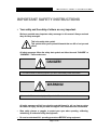
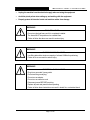
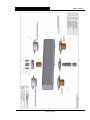
S-640 Universal Test Frame User Manual Version 2.0 Durham Geo Slope Indicator 2175 West Park Court Stone Mountain, GA 30087 USA Phone: 800-837-0864 or +1.770.465.7557 Fax: 770.465.7447 e-mail: [email protected] www.DurhamGeo.com Disclaimer Durham Geo-Enterprises, Inc. (including all affiliates to include its trade name of DGSI) makes no representations or warranties with respect to the contents hereof and specifically disclaim any implied warranties of merchantability or fitness for any particular purpose. Durham Geo Slope Indicator reserves the right to revise this publication and to make changes from time to time in its content without obligations to notify any person or organization of such revision or changes. IMPORTANT – Read & Save these instructions Before beginning installation procedures, these Installation and Operating Instructions should be studied carefully. Doing so will make installation easier and help you in the future if you have questions. The installation and operation should also be in accordance with local regulations and accepted codes of good practice. Call Durham Geo Slope Indicator if you have any questions; when you call you will need the model and serial numbers. Information Record Model #: ____________ Serial #: ______________ Sold By: ___________________ Date Purchased: _____________ You will need the serial number if you call DGSI for service or support. Page 2 of 30 Page 3 of 30 Table of Contents IMPORTANT SAFETY INSTRUCTIONS ..................................................................................................... 5 RECEIVING / SETUP ................................................................................................................................... 7 1.0 2.0 Receiving Procedures .................................................................................................................... 7 Setup Procedures ........................................................................................................................... 7 OPERATION ................................................................................................................................................. 9 1.0 2.0 3.0 4.0 5.0 6.0 Construction and Principles of Operation ....................................................................................... 9 Safety Features .............................................................................................................................. 9 General Specifications .................................................................................................................. 10 Controller, Operating Commands, & Sample Screens ................................................................. 11 Operating Commands .................................................................................................................. 12 Main Screen Sample Shots .......................................................................................................... 14 UPKEEP ..................................................................................................................................................... 16 1.0 2.0 Cleaning and Periodic Checkups ................................................................................................. 16 Calibration..................................................................................................................................... 17 REFERENCE .............................................................................................................................................. 18 1.0 2.0 3.0 4.0 5.0 Troubleshooting ............................................................................................................................ 18 Limited Warranty .......................................................................................................................... 19 Information Record ....................................................................................................................... 20 Calibration Record ........................................................................................................................ 21 S-640 Assembly Drawings ........................................................................................................... 22 Page 4 of 30 S-640 UNIVERSAL TEST FRAME I M P O R T A N T S A F E T Y I N S T R U C T I O N S IMPORTANT SAFETY INSTRUCTIONS Your safety and the safety of others are very important. We have provided many important safety messages in this manual. Always read and obey all safety messages. This is the safety alert symbol. This symbol alerts you to potential hazards that can kill or hurt you and others. All safety messages follow the safety alert symbol and either the word “DANGER” or “WARNING”. These words mean: DANGER! You can be killed or seriously injured if you don’t immediately follow instructions. WARNING! You can be killed or seriously injured if you don’t follow instructions. All safety messages will tell you what the potential hazard is, tell you how to reduce the chance of injury, and tell you what can happen if the instructions are not followed. Wear safety glasses or goggles to protect your eyes when operating, calibrating, maintaining, or ortherwise using the equipment. Be sure to understand ALL operating procedures BEFORE using equipment. Page 5 of 30 S-640 UNIVERSAL TEST FRAME I M P O R T A N T S A F E T Y I N S T R U C T I O N S Unplug the machine from the electrical supply when not using the equipment Avoid the pinch points when setting up and working with the equipment. Properly protect all electrical cords and machine cables from damage WARNING! TIP OVER HAZARD Do not use the load frame until it is completely installed. The frame MUST be positioned on a stable base. Failure to follow the above can result in serious injury. WARNING! EXCESSIVE WEIGHT HAZARD Use lifting aids with a minimum capacity of at least 1200lbs for positioning. Failure to do so can result in serious injury. WARNING! ELECTRICAL SHOCK HAZARD Plug into a grounded 3 prong outlet. Do not remove ground plug. Do not use an adaptor. Do not use an extension cord. Disconnect power BEFORE servicing. Replace all parts and panels before operating. Failure to follow these instructions can result in death, fire, or electrical shock. Page 6 of 30 S-640 UNIVERSAL TEST FRAME R E C E I V I N G / S E T U P RECEIVING / SETUP Congratulations and thank you for purchasing the Durham Geo Slope Indicator S-640 Universal Test Frame. To insure optimum performance it is strongly suggested that the operator’s manual be read prior to unpacking and setup of the load frame. Failure to follow the installation and operation instructions may result in voiding the warranty of the equipment. By following the setup, operating, and maintenance procedures you can enjoy a lifetime of use. 1.0 Receiving Procedures 1.1 Onsite Delivery/Damage in Transit: This product has been packed to insure that it arrives at your location free from damage. Damage in shipping is rare but may happen so always check for evidence of damage or loss before signing for any shipment. Do not sign for any shipment with apparent damage until the carrier notes damage on the receipt and signs same. Do not discard original packing materials until equipment has been fully examined in operation. If damage to contents is evident, an examination and report by the transport agent must be requested. If damage is found after the carton is unpacked, notify the transport agent immediately to arrange an inspection and provide you necessary forms for filing a concealed damage report. Concealed damage must be reported to and inspected by the carrier within ten days. 1.2 Unpacking/Inspection: Remove the outer protective wrapping and the outside crate walls, being careful to not damage the main housing. Remove the supporting braces and steel banding from around the main housing. Closely inspect the frame and electronics for damage. Inspect all packages received and note any missing parts. If you find any problems, please contact DGSI immediately at 1-800-837-0864. 2.0 Setup Procedures 2.1 Due to the weight of the Load Frame, extreme care MUST be taken when removing the machine from the shipping pallet! 2.2 By using a lifting strap, with a minimum capacity of 1200lbs, around the top cross beam, the frame can be lifted using a fork lift or hoist. 2.3 Place the load Frame on a sturdy, level surface capable of supporting at least 1000lbs. 2.4 It is important for the machine to be as level as possible. Using a bubble level, verify that the upper cross beam is parallel to the loading platen. The machine has (4) leveling feet on the bottom which can be used to level the machine. These leveling feet can be removed, if desired, to allow the machine to bolted down directly. Page 7 of 30 S-640 UNIVERSAL TEST FRAME R E C E I V I N G / S E T U P WARNING! MACHINE STARTUP HAZARD Before continuing, verify the on/off button on the front panel is in the OFF position. This is when the red inner button is flush on top with the gray outer base of the switch. Failure to do this could result in the machine accidentally starting up when the power cord is connected. It is the customer’s responsibility to assure that the electrical installation is adequate and in conformance with all national and local codes and ordinances. Failure to do so can result in serious injury. 2.5 Plug the black (3) wire power supply cord with the (3) prong plug into a 120V, 60Hz, AC only, 15 amp, fused electrical power supply. We recommend a time-delay fuse or circuit breaker, along with a separate circuit. 2.6 After all connections are securely fastened, with no load on the platen, push in the on/off button to the “ON” position (the red inner button will be down inside the outer gray base). This will apply power to the Load Frame and Control Panel. 2.7 Two auxiliary outlets have been placed in the rear of the Load Frame for your use and convenience. DO NOT exceed 1amp of total current in the two outlets. Excessive loading may cause damage to the Load Frame and/or blow the internal fuse. Page 8 of 30 S-640 UNIVERSAL TEST FRAME O P E R A T I O N OPERATION 1.0 Construction and Principles of Operation 1.1 Lower mainframe is CNC machined from structural steel and welded to provide a high strength structure for supporting the drive assembly, screw jack mechanism, and strain rods. 1.2 Strain rods are constructed of high strength steel and precision machined. 1.3 Upper loading cross beam is constructed of structural steel and contains a high strength, precision machined center spindle to provide the customer with the ability to attach customized load cells, proving rings, and loading platens. 1.4 Screw jack drive unit for ease of maintenance, high reliability, and long life. 1.5 DC Servo “smart” motor drive for high precision and ease of control. 1.6 Overtorque limit by controller monitoring and motor stall conditions. 1.7 High safety factor for repeated use to a maximum load limit of 40K lbf. 1.8 Built in micro-processor based controller is capable of providing constant velocities between the speeds of 0.001 in/min and 0.200 in/min. The test velocity can be easily set by the operator on the convenient front mounted control panel. 1.9 Load Frame is capable of reaching maximum capacity in compression or tension. Note: The Load Frame as delivered is setup for compression testing. If the customer desires to run tests in tension the load nuts (brass) must be swapped with the non-load nuts (black) on the upper cross beam. See illustration in the appendix. WARNING! OVERLOAD HAZARD The non-load nuts (black) are for positioning the upper cross beam ONLY and are not capable of supporting the maximum load capacity of the frame. The load nuts (brass) MUST ALWAYS be on the load supporting side of the cross beam. Failure to do so can result in serious injury. 2.0 Safety Features 2.1 Limit Switches: If either the upper or lower limit of platen travel is reached the machine will stop and the phrase “YOU HAVE REACHED THE (UPPER/LOWER) LIMIT" will be displayed. This will notify you that a limit has been reached and that the test that was running will not be completed. Page 9 of 30 S-640 UNIVERSAL TEST FRAME O P E R A T I O N After pressing F6 (REVERSE or FORWARD as required), the machine will move off the corresponding limit switch and return to the startup display awaiting another command. NOTE: The limit switches were installed as a safety feature to prevent over travel. Use the HOME key to return the platen back to its original operator zeroed starting position rather than using the limit switches. 2.2 Fuses: The Load Frame is fused at the power cord. If the fuse is blown, replace it with a 250V, 6amp, slow-blow fuse. 2.3 Auxiliary Outlets: Two auxiliary outlets have been placed in the rear of the Load Frame for your use and convenience. DO NOT exceed 1amp of total current in the two outlets. Excessive loading may cause damage to the Load Frame and/or blow the internal fuse. 3.0 General Specifications Velocity (Speed) Control: Onboard computer with LCD Display LCD Display provides for operator ability to: 1. Select Velocity (Speed) 2. Select Platen Travel Distance (Position) 3. Return Home 4. Rapid Up/Down 5. Start/Stop Speed Range: Variable by operator setting from 0.001 in/min up to 0.200 in/min Bottom Platen: 6¼” diameter x 1” thick steel Platen Travel: 3” maximum Upper cross beam: Fully adjustable down to bottom platen. Adjustable center attachment (max. 6”) Safety switches: Upper and lower limit safety cut-out switches Strain Rods: 2” diameter ACME threaded high strength steel rods Distance between columns: 18” horizontal clearance Daylight (without load measurement device): 40” vertical clearance Overall Dimensions: approx. 30 ½” W x 20” D x 74” H Base to top of platen: 21” Power: 110 VAC, 60 Hz, 5 A (2) Auxiliary sockets, 2 A rated Weight: approx. 700 lbs Paint: All parts painted or plated for rust protection Page 10 of 30 S-640 UNIVERSAL TEST FRAME 4.0 Controller, Operating Commands, & Sample Screens 4.1 Controller O P E R A T I O N Below is a diagram of the controller. This computer is the “brains” of the machine. By using it, you can control all the parameters of the machine and the tests you will be running, such as: 1. Fast Up/Down (to quickly move the platen up or down prior to a test) 2. Platen travel [in] (in test mode) 3. Platen speed [in/min] (in test mode) 4. Run Mode The S-640 Universal Test Frame’s menu system is very simple to use. Upon powering up the machine, the readout on the controller will come to the startup screen. Page 11 of 30 S-640 UNIVERSAL TEST FRAME 5.0 Operating Commands 5.1 MOVE (F1) O P E R A T I O N All movement is referenced from the position indicated on the first line of the controller display (actual position: = +X.XXX inches). The indicated position does not necessarily reflect the current position of the platen in reference to the upper and lower limits. Example: If the indicated position on the display is 0.000, the platen could be up 1 inch from the lower limit, leaving a maximum of approximately 2 inches of upward movement. Indicated positions range from -3 inches to 3 inches. 5.1.1 TO START ENTERING MOVE DATA, PRESS F1 (MOVE): Press the MOVE key (F1 in the upper left hand corner). The display will then move to the command screen awaiting a commanded position. 5.1.2 ENTER THE COMMANDED POSITION, PRESS ENTER: The third line will have 1.0000 or the last commanded travel position displayed. Press ENTER to accept the present displayed travel position or input a new desired travel position. If you press the wrong key(s), use the DEL key to remove the last entered digit(s). After entering the correct value, press the ENTER key at the bottom right hand comer. Possible positions range from -3.0000” to 3.0000”. 5.1.3 ENTER THE COMMANDED VELOCITY, PRESS ENTER: The fourth line will have 0.010 or the last commanded velocity displayed. Press ENTER to accept the present displayed velocity or input a new desired velocity. If you press the wrong key(s), use the DEL key to remove the last entered digit(s). After entering the correct value, press the ENTER key at the bottom right hand comer. The velocity range is 0.001 in/min to 0.200 in/min. 5.1.4 PRESS F5 (START) or F6 (STOP): The final step is to press F5 or F6. The start key, F5 (START), will start the test and cause the machine to perform the move at the rate and distance previously entered. Pressing the stop key, F6 (STOP), will prevent any movement of the platen and will cause the display to return to the startup screen. This allows you to re-input data if you made an error when entering the rate or distance. 5.2 HOME (F2) 5.2.1 PRESS F2: This key will move the platen back to its original operator input zero position. If the position indicated on the screen is positive, the platen will move downward until the indicated position is 0.000. If the indicated position is negative, the platen will move upward until the indicated position is 0.000. Maximum travel speed is .200 in/min therefore, 3.0” of travel will take approximately 15 minutes. Page 12 of 30 S-640 UNIVERSAL TEST FRAME 5.3 O P E R A T I O N ZERO (F3) 5.3.1 PRESS F3: This key will force the indicated position display to 0.0000, regardless of the actual platen position. This position will be the new origin for the platen. Note: Once the operator has the platen in the desired test position, then the F3 key should always be used to make this the new origin before moving to the command screen and entering test position and velocity parameters. 5.4 F-UP (F4) 5.4.1 PRESS F4: This is the FAST UP key. This key will move the platen upward until the upper limit switch is reached or until the STOP key (F6) is pressed. Maximum travel speed is .200 in/min. Maximum travel distance is 3.0 inches. 5.5 F-DN (F5) 5.5.1 PRESS F5: This is the FAST DOWN key. This key will move the platen downward until the lower limit switch is reached or until the STOP key (F6) is pressed. Maximum travel speed is .200 in/min. Maximum travel distance is 3.0 inches. 5.6 STOP (F6) 5.6.1 PRESS F6: This is the STOP key which will halt the chosen command. Page 13 of 30 O P E R A T I O N S-640 UNIVERSAL TEST FRAME 6.0 Main Screen Sample Shots 6.1 STARTUP SCREEN COMMAND SCREEN M O V E F-DWN (Fast Down): Runs the platen DOWN at machine maximum of 0.200”/min. HOME: Returns platen to where the “ACTUAL POSITION” = 0.000. ZERO: Resets the current “ACTUAL POSITION” value to 0.000. All moves are absolute based on this position. If a number is input wrong, simply use the Del on the keypad to backspace the wrong number and retype. F-UP (Fast Up): Runs the platen UP at machine maximum of 0.200”/min. COMMAND POSITION: This is the platen move distance as related to the displayed “ACTUAL POSITION” on the startup screen (i.e. this displayed distance of “-.100” would cause the platen to move down 0.100”. Programming a positive distance of “.100” would cause the platen to move up.) TRAVEL VELOCITY (in/min) Displayed value would move the platen at 0.0100 in/min. Page 14 of 30 S-640 UNIVERSAL TEST FRAME START: When all values are deemed satisfactory, then press “START” to start the platen moving and the test running. O P E R A T I O N STOP: To immediately stop a test or to re-enter incorrect data press “STOP”. The display will return to the startup screen. The motor stall screen is displayed when the Load Frame has reached its operating limit or, in the FAST UP mode only, a reduced limit. This reduced limit in FAST UP is done to help protect attached instruments in case of operator error. Page 15 of 30 S-640 UNIVERSAL TEST FRAME U P K E E P UPKEEP 1.0 Cleaning and Periodic Checkups 1.1 Periodically wipe down the outside of the machine to keep dust and dirt from building up on the outside surfaces, especially the keyboard and LCD screen. Computer monitor screen cleaner works well on the control panel LCD. 1.2 Every 3-6 weeks spray the tie rods and center spindle with a good quality lubricant. A silicon spray or dry lubricant works well. 1.3 Monthly inspect the electrical supply connection. It is good practice to protect electronic devices by using a good quality surge protector. 1.4 Monthly inspect the machine for loose fasteners. 1.5 Yearly disconnect the supply power and remove the rear cover. Using DRY compressed air blow out the inside of the case and visually inspect the running gear. Use a silicon lubricant on the chain drive mechanism. IMPORTANT! All servicing and repair work on the machine requires special training. This is especially true of the machine’s safety equipment. If your machine needs repair please contact us BEFORE attempting to make any repairs. We have available professional service technicians for repair and service. WARNING! SAFETY HAZARD NEVER use the machine with faulty safety equipment! The machine’s safety equipment must be checked and maintained in working order. Failure to do so can result in serious injury. Page 16 of 30 S-640 UNIVERSAL TEST FRAME U P K E E P 2.0 Calibration 2.1 The Load Frame is calibrated before it leaves the factory. The calibration certificate is enclosed with the machine. If ASTM on-site calibration is required, the enclosed certificate cannot be used as a replacement. 2.2 In most instances a recalibration is not required. 2.3 It is good practice to have the machine calibrated on a minimum two year rotation. If tests are being run per ASTM standards then it is required to have the Load Frame calibrated every (12) months. 2.4 Only a certified calibration technician should calibrate the S-640 Universal Test Frame. Page 17 of 30 R E F E R E N C E S-640 UNIVERSAL TEST FRAME REFERENCE 1.0 Troubleshooting 1.1 Problem Cause Solution Sample does not fit into frame Crossbeam is too low. Adjust crossbeam (higher). The sample does not hit upper platen even when the lower platen is fully extended Crossbeam is too high. Adjust crossbeam (lower). Platen will not move and overtravel screen is displayed Platen has overtraveled. Use the corresponding F key on the controller overtravel screen. Internal wires are disconnected. Call Factory. 9-pin plug on the bottom of the controller is disconnected. Reconnect plug in COM1 on the controller. Controller screen does not light up at startup Power is cut off from the controller. Check the power plug on the bottom of the controller. Power LED does not come on when S-640 is turned on. Blown fuse. Replace fuse in back of the machine. Shaft key is broken. Replace key. Call Factory. Chain has slipped off or is broken. Check the chain. Call Factory. Motor is not communicating with controller at startup Motor is running, but there is no platen movement Page 18 of 30 S-640 UNIVERSAL TEST FRAME R E F E R E N C E 2.0 Limited Warranty 2.1 Durham Geo-Enterprises, Inc. / Slope Indicator (“DGSI”) warrants the products manufactured by DGSI to be free of defects of workmanship and material on a product basis. The products accompanied by this Warranty Statement are warranted for a period of (90) DAYS from the date of delivery to the customer. The obligation of DGSI is hereafter limited to replacement or, at its option, repair of products returned to it, should DGSI's examination disclose, to its satisfaction, that the products were not free from defects. Products repaired or serviced by DGSI are warranted against defects in workmanship and materials for a period of 90 days, or the remainder of the original warranty period, whichever is greater. IN NO EVENT SHALL DGSI BE LIABLE FOR CONSEQUENTIAL OR SPECIAL DAMAGES, OR FOR INSTALLATION, ADJUSTMENT, LOST PROFITS OR OTHER COSTS WHICH MAY ARISE IN CONNECTION WITH SUCH PRODUCTS. THE APPLICABLE PRODUCT WARRANTY EXTENDS ONLY TO THE ORIGINAL CUSTOMER OF DGSI OR ITS AUTHORIZED DISTRIBUTOR, AS THE CASE MAY BE, AND IS EXPRESSLY IN LIEU OF ALL OTHER WARRANTIES, EXPRESS OR IMPLIED, WHETHER OF MERCHANTABILITY OR FITNESS FOR ANY PARTICULAR PURPOSE OR USE, AND OF ALL OTHER OBLIGATIONS AND LIABILITIES OF ANY KIND AND CHARACTER. EXCEPT FOR THE WARRANTY APPLICABLE TO THE SPECIFIC PRODUCT(S) PURCHASED, DGSI MAKES NO WARRANTY OF MERCHANTABILITY OF THE GOODS OR OF THE FITNESS OF THE GOODS FOR ANY PURPOSE. THERE ARE NO WARRANTIES WHICH EXTEND BEYOND THE DESCRIPTION ON THE FACE HEREOF. Any products, components or accessories that are not manufactured by DGSI and are supplied by other manufacturers are subject to their respective warranties. Certain products will carry their own warranties. For further assistance: Call 1-800-837-0864 (toll free) or (770) 465-7557 E-mail to [email protected] Page 19 of 30 R E F E R E N C E S-640 UNIVERSAL TEST FRAME 3.0 Information Record Information Record 3.1 Frame Model #: S-640 Frame Serial #: ______________ Sold By: ___________________ Date Purchased: _____________ The model and serial numbers for the frame and readout are listed on the side and back of the equipment, respectively. You will need these numbers if you call DGSI for service or support. We can be reached between 8:00 am and 5:00 pm Eastern Standard Time (EST) at: __________________________________ Telephone: 1-800-837-0864 (outside Georgia, USA) (770) 465-7557 (inside Georgia, USA ) __________________________________ Fax: (770) 465-7447 __________________________________ Page 20 of 30 R E F E R E N C E S-640 UNIVERSAL TEST FRAME 4.0 Calibration Record 4.1 Date Performed By: Comments THANK YOU for CHOOSING DGSI PRODUCTS! Your comments and observations on this manual and its associated machinery are welcome. Please call us with any corrections or improvements you feel would improve the quality of this product. Your feedback as the end user of the device is important to our business. Page 21 of 30 S-640 UNIVERSAL TEST FRAME 5.0 S-640 Assembly Drawings 5.1 Drawing #602245 Upper Cross Bar & Spindle Assembly 5.2 Drawing #602237 Control Panel Assembly 5.3 Drawing #602152 Microswitch Trip Arm Assembly 5.4 Drawing #602183 Input Drive Component Assembly 5.5 Drawing #602147 Main Beam & Electrical Drive Subassembly 5.6 Drawing #602248 S-640 Load Frame Overall Assembly Page 22 of 30 R E F E R E N C E S-640 UNIVERSAL TEST FRAME Page 23 of 30 R E F E R E N C E S-640 UNIVERSAL TEST FRAME Page 24 of 30 R E F E R E N C E S-640 UNIVERSAL TEST FRAME Page 25 of 30 R E F E R E N C E S-640 UNIVERSAL TEST FRAME Page 26 of 30 R E F E R E N C E S-640 UNIVERSAL TEST FRAME Page 27 of 30 R E F E R E N C E S-640 UNIVERSAL TEST FRAME Page 28 of 30 R E F E R E N C E S-640 UNIVERSAL TEST FRAME Page 29 of 30 R E F E R E N C E S-640 UNIVERSAL TEST FRAME Page 30 of 30 R E F E R E N C E