1
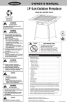
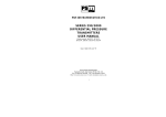
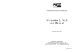
User's Guide
Issue 3. January 2001
PSM Instrumentation Ltd
Unit 3 Burrell Road, Haywards Heath, W Sussex RH16 1TW
Tel: 01444 410040 Intl: 44 1444 410040
WWW.PSM-SENSORS.CO.UK
EMAIL [email protected]
1
CONTENTS
Introduction
3
About this Manual
3
Operation
Mouse Driven Systems
Keyboard Driven Systems
Alarms
- File
-Print
-Log
- Manual Reset
4
5
5
6
7
8
8
8
Understanding The Display
Graphic Display of Volume
Alarm Neon
Numeric Display
9
9
9
9
Single Tank Display
Density / Temperature Correction
Specific Gravity & Density
Inert Gas Correction
10
11
12
13
Password
15
On-line Help
15
Trouble shooting
16
2
INTRODUCTION
Tankview is a simple to operate graphical display package running in the
windows environment, which provides the user with a clear picture in
both bargraph and numeric format of the current quantity of liquid within
any type of storage tank.
Displays are normally arranged in a number of windows according to
tank duty, i.e. ballast, cargo, fuel oils, fresh water etc. The windows
provide an overview of the current situation and from these the user is
able to select a single tank display which provides comprehensive data
for that tank alone.
Input data may be collected from a number of sources and is received via
the PC's serial port. Tankview will have been configured with the
necessary communication package, and in operation this aspect is
transparent to the user as scanning & up-dating of values is an automatic
background function.
Tankview also provides alarm reporting and logging functions, which,
dependent upon the requirements, may simply provide visual warnings
and reports or may be enhanced to provide outputs for remote alarm/
control purposes.
ABOUT THIS MANUAL
This manual covers only the operational aspects of Tankview and is
supplied where a complete pre-configured package has been ordered
with all parameters entered to suit the intended duty.
Certain operational parameters which may change in normal service can
be adjusted by the user and these functions are detailed in this manual.
Where a configuration change which is not covered by this manual is
required please refer to the system provider, whose details will be found
under the <support> item in the main help menu.
3
OPERATION
Operation of the system follows standard Windows practice. Access
to the various information pages requires either a mouse or other
pointing device, or in environments where this may not be suitable the
system may be keyboard driven.
A standard Windows menu bar at the top of each page provides the
options available to the user. In addition to this manual the system
provides on-line help which covers all main aspects of operation.
Under normal circumstances where the PC employed is dedicated to
the function of tank monitoring, Tankview will automatically start
when the system is powered up. Where this is not the case Tankview
is accessed from the start button and by selecting the program group
Tankview and then the icon for Tankview itself.
Mouse operation follows standard Windows conventions.
On keyboard driven systems, standard Windows convention is employed. The Menu bar is activated using the <Alt> key and the
arrow keys are used to highlight the desired option. Once
highlighted, press <enter> to select the menu item. Certain menu
items also feature an underscored character. These are “Hot keys”,
keying in the underscored character selects the menu option.
The appropriate icon is then highlighted using the arrow keys and the
Enter key used to run the program.
When Tankview is initially run the user will be presented with a
screen similar to the following:
Caption Bar: The primary function of the caption bar is to advise
Tankview status ie., running, stopped, or design mode. It also shows
which window is currently being displayed.
4
Control-menu box
Menu Bar
Caption Bar Maximize Button
Minimize Button
Title
Bar
Tank
object
Menu Bar: This shows the menu functions available. These will vary
depending upon the screen currently displayed.
The above screen shows the various display windows arranged in a
cascade, alternatively these can be used in a tile format by selecting this
from the Window option on the Menu bar.
Mouse driven systems
To select a particular display window left click on the appropriate
window Title bar, this brings it to the front. A further click on its
maximize button will display the page at full screen size. To change to
another window, left click on the Window 'menu' option, select Cascade
and repeat as above.
Keyboard driven systems
Starting from the cascade display, press function key <F10> to activate
the menu bar (File will be highlighted). Use left and right arrows to
5
highlight Window and then the up/ down arrows to highlight the
desired window and press <Enter>.
Alternatively, pressing the <Control> and <F6> buttons
simultaneously will cause the active display window to scroll round to
the front. When the required window is active press <F10> to
activate the menu bar, press left or right arrows until the Controlmenu box for the active window is highlighted. Next press the down
arrows to bring up the menu options and select maximize to display
the full window.
To return to the cascade display either select minimize in the same
way as detailed above for maximize, or select Window and then
Cascade from the menu bar.
In addition to the windows displaying tank content there is an alarm
list window. Depending upon how the system has been configured
each tank may have up to four associated alarm points. If these are
activated by tank content dropping below or rising above the setpoint, a message is displayed within the alarm window in a standard
Windows list box format.
This alarm window may be selected for viewing in exactly the same
way as the tank display windows.
6
The Alarm window has two buttons. The Menu button pulls up a list of
functions available to deal with alarms, and the Reset alarm button is
self-explanatory. For keyboard driven systems the appropriate button is
selected using the <tab> key to switch the highlight between the two, and
the <enter> key to operate.
For mouse driven systems position the cursor over the required button
and left click. When the Menu button is pressed the following options
appear:
File
This leads to two further options Create and Size.
Create: when selected using enter calls up a standard windows dialogue
box which enables a file to be created where all alarms may be logged
as they occur. The directory and file name where these alarms are to be
logged should be entered using normal Windows procedures.
Size: enables the user to limit the log file size to prevent it from
becoming too large. The default value is 0.05 Megabyte which will hold
approximately 400 alarm logs. Once this value is exceeded the system
will stop logging alarms to the file and an on-screen warning advises
that the file size has been exceeded. A new file should be created
7
It is suggested that a new alarm log file is created for each month or
voyage or some other appropriate demarcation, which will prevent the
file from becoming too large and making it difficult to locate particular
events if the files are reviewed at some point in the future.
Print
Where a printer is installed with the system an automatic printout can
be invoked after XX number of alarm events. Enter the required
number where prompted. Note: an entry of zero disables this facility.
Current list: Selecting this facility will provide a hard copy printout of
all alarm events in the current list.
Log/audible alarm/manual reset: These are on/off selections, on is
indicated by a tick alongside the option.
When Log is switched ON, all alarm events are automatically logged
to the file created by the user The ON status is indicated by a check
mark beside the menu item..
When Audible alarm is switched ON, any alarm event occurring will
cause the PC to sound an internal alarm.
When Manual reset is ON the user is able to clear alarm events from
the current displayed list. To do this the appropriate event line must be
highlighted either using a mouse or up/down arrows and the Reset
alarm button pressed either by <Tab>/<Enter> from the keyboard or
left click on the mouse.
The operator will be
prompted
for
a
confirmation of the
selected alarm to be
cancelled. Pressing Yes
will reset the alarm.
8
Text box
Alarm
neon
Graphic
display of
tank
volume
Numeric
indication
UNDERSTANDING THE DISPLAY
Each display window contains one or more tank objects. These each
cover one particular tank and appear as a rectangular box within
which any or all of the following information may be displayed.
1) Graphic display of volume - shown as a bargraph which progressively fills the box as its capacity increases.
2) Alarm neon - where alarms have been assigned to the tank and
when any become active a flashing red neon will appear in the top
right-hand corner of the box.
3) Numeric indication of the following - Volume, level, free capacity,
ullage, weight, temperature, loading rate, inert gas pressure.
Note that the actual information displayed and colours employed
will depend upon the original contract requirements.
9
The size and spacing of the tank object boxes will depend upon the
amount of information in each display window. In general, where
practical, display windows are arranged in a format representative of
a site or ship plan view.
To assist in tank identification, additional text boxes may be present
in a display window. These simply clarify the function of individual
groups of tanks. Similarly some systems may feature a “background”
picture to clarify the display. For example a ships outline may be
used to show the relative position of tanks.
Single Tank Display
To access the Single tank display on mouse driven systems position
the cursor over the appropriate tank object and double left click on
the mouse. For keyboard driven systems press <F10> to activate the
Menu bar, left right arrows to highlight View and <Enter> or down
arrows to display a list of all tanks on the active display window.
Use the up-down arrows to highlight the desired tank and <Enter> to
display. To return to the Display window press <Enter> or click on
the Okay button with the mouse driven system.
The single tank display page allows the user to print a detailed report
of the current status of the tank (assuming a printer is installed). On
mouse driven systems simply left click on the Print button. For
keyboard operation use the <Tab> keys to highlight the Print button
and press <Enter>.
10
Density & Temperature Correction
The display also has three buttons “Temp”,“Density” & “Product”.
These buttons enable the user to correct the display for actual
conditions such that true values are displayed for level and volumetric
indication.
Depending on the original configuration of the system it may be
observed that some or all of these buttons are “greyed
out” (disabled). If this is the case fixed values have been entered, and
no operator changes are possible.
Assuming changes are enabled the following will apply:The system is configured with both a base density and a temperature
coefficient for each tank and its stored liquid. The base density value
provides a reference point of a certain weight per M3 at a specific
temperature, and the coefficient determines the % change in this
weight per degree centigrade. Thus if the user changes the
temperature value to to reflect actual conditions Tankview uses the
base density and temperature coefficient to calculate the actual
density.
To change either of these two parameters, using the mouse click on
the relevant button, or use the <Tab> key to highlight and <enter to
select. A further display appears with a prompt for the new value to
be entered.
Temperature dialogue box
Since actual temperature and actual density are interrelated it will be
observed that changing one parameter causes the other to
automatically recalculate and update the display. In practice only the
actual temperature is normally known and this is the parameter which
should be changed.
11
Density dialogue box
NOTE: Caution is advised before making any changes to either of
these parameters. In practice the effects of a change in temperature
are small, typically 0.07% for a 10oC change for oils, and thus do
not introduce significant errors if uncorrected. On the other hand
an erroneous entry of information could cause large errors in
displayed information.
The user should not confuse the specific gravity value of a product
with its density. Specific gravity is a factor which relates the weight
of liquid to that of water and whilst it may be used to calculate its
base density, (see below) it must not be used to enter a value for
actual density.
As stated previously Tankview is pre-configured with base density
and coefficient values for each particular tank. If the duty of a tank
changes meaning these values may require changing please contact
the system provider. Contact details are available from the main
help menu.
Specific Gravity and density
Specific gravity is a factor which compares the relative density of a
particular liquid with water which has an S.G value of 1.00. It can be
employed to derive a base density value for a particular liquid but
does not provide a coefficient value.
12
Example:- For an oil with an S.G. value of 0.8
Base density of water
= 999.972 Kg/M3 @ 4 oC
(At 4 oC water is at its most dense)
Base density of oil at 4 oC
=999.972 x 0.8
=799.977
Product Dialogue box
If selected during original configuration, the current stored product
will be shown in the tank object display.
It is also shown in the single tank display. To change the stored
product using a mouse left click on the <Product> button. From the
keyboard use <Tab> to highlight the Product button, then <enter>.
The following dialogue box appears:Using a mouse activate the drop down list and highlight / select the
appropriate product. From the keyboard use the up/down arrows
until the correct product appears in the list box.
Click the <OK> button with a mouse or use <tab> to highlight then
<enter>.
It will be observed that the new product is shown in the single tank
display.
Inert gas correction
On tanks which are not freely vented a secondary transmitter is
installed to measure the overpressure, ie the difference between the
free space pressure and atmospheric. The system then corrects the
displayed volume for the effects of top pressure.
When this system is in use the top pressure is displayed on the Single
tank display page.
13
Passwords may be changed from the menu option Password in the
filemenu on the main menu bar.
To change the password follow this procedure:-
1
2
3
4
5
6
Select Change
Type your old password
Type your new password
Click change
Repeat your new password
Click change
Your password is now saved
On-line help
The programme includes standard Windows on-line help.
Select<Help>from the main menu to view the above screen.
Print Setup
There is no facility within “Tankview” to change printers. The
Windows default printer will be used which can be set up via the
Control Panel within Windows.
The program includes standard Windows help facilities. Pressing the
<F1> function key or selecting the <Help> menu item the help facility
will be presented as below. For more information about using the help
facility please refer to your Windows manual.
15
It may also be shown on the main display page as a separate object in
it’s own right.
NB. Any changes to product details are immediately effected.
However, unless they are saved to amend the base configuration
and the system is shut down for any reason, it will restart with
the default values and the changes will have to be made again.
If changes made are to be considered as permanent they should
be saved using the <save> menu option in the <file> menu on the
main menu bar.
This will write the changed values into the basic configuration
such that they are retained if the system is shut down and
restarted.
User and Supervisor Password
When the system is running only functions that are related to normal
operation are available. To stop the program the user needs the user
or supervisor password. To enter design mode the supervisor
password is needed. By default these are 1234 for both. The
password is a 4 digit combination and must be entered correctly for
the system to accept it.
The password will also be required to exit the system and return to
Windows in which case an additional message will be displayed.
User Password dialogue box:
Supervisor Password dialogue box:
14
Trouble Shooting
If an error occurs it is important to make a note of any error messages or
symptoms and the task that was being performed when the error occured. These
should then be refered back to the system provider.
If communication with the data aquisition devices is lost Tankview will display a
warning message, typically it will look similar to this:
The PC is still running
1
No input data from the data
aquisition device - cable loose or
device malfunctioning, check
cables and other hardware.
2
PC memeory exhausted generally due to 3rd party
programs running concurrently
with Tankview, Shut down all
other programs and try again.
3
No more disk space - if you are
logging alarms this may occur after some time, copy down to disk or
delete old log files.
4
Incorrect configuration - entered parameters do not conform to
programme limitations, check any recent changes for invalid entries.
The PC is not running
1
Black screen - check the screen is turned on and the power cables are
connected.
2
Completely dead - check fuses and power supply, refer to computer
manufacturers documentation.
Input device malfunctioning
1
Refer to input device documentation.
FOR FURTHER ASSISANCE CONSULT SERVICE AT :PSM Instrumentation Ltd
Unit 3 Burrell Road, Haywards Heath, W Sussex RH16 1TW
Tel: 01444 410040 Intl: 44 1444 410040
WWW.PSM-SENSORS.CO.UK
EMAIL [email protected]
16