1
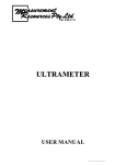
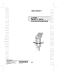
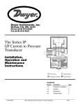
PSM INSTRUMENTATION LTD
Ultrameter 5, 7 & 10
user Manual
Issue C date: 18/06/2001
Burrell Road Industrial Estate
Haywards Heath, West Sussex RH16 1TW, UK
Tel: +44 (0)1444 410040 Fax: +44 (0)1444 410121
Http://www.psm-sensors.co.uk E-mail: [email protected]
Doc Ref: Man 03
1
The Ultrameter is designed for measuring liquid
levels in open and closed tanks.
There are intrinsically safe versions available in all
ranges. These are approved for use in hazardous
areas to EEXia IIC T6.
The nose section is manufactured from TEFLONtm a
Duponttm material resistant to most chemicals, and
includes an integral temperature sensing element to
ensure temperature compensation and correct level
measurement at all temperatures. The electronics
housing is manufactured from UPVC. The entire
assembly is sealed and protected against accidental
immersion.
The transducer transmits a series of short, controlled, ultrasonic pulses towards a
surface. The reflected echoes are intelligently conditioned remove any noise, and
the time taken for the echoes to reach the sensor face are calculated and converted
to distance for transmission as a mA current loop output.
The transmitter uses on-board LED’s to confirm power is on and that the transmitter is operating correctly. To calibrate, the zero and span levels of the tank are
entered into the transmitter by simply touching the ’Z’ & ’S’ targets, on the transmitter body, with the magnetic key provided.
Tank Mounting
Flange Mount
When flange mounting,
use a gasket to ensure
acoustic de-coupling
hand tighten only.
DN50 PN10, 2” ANSI,
JIS10K2B
Suspended
Threaded Pipe
1/2” conduit
From it’s
Ensure acoustic
pipe/hanging
own cable de-coupling by hand Preferred for dam,
tightening only
filter beds and
open channel
application
2
Transmitter Positioning on Tank Roofs
1/6 D
Avoid mounting the transmitter in the centre of the
roof of the tank.
The recommended position for the transmitter is
1/6 of the diameter from the tank wall.
Dimensional Details
D
90 mm
2” BSP
Thread
55 mm
45 mm
Supply Nominal 24 V
Intrinsically Safe EEx models only
The transmitter is certified intrinsically safe with barriers only.
Recommended barriers:
MTL 787S+, Elcon 1620-2D-P -R
Inspection Authority:
SABS S/R164X
Certification:
EEx is IIC T6 No. 5478/945979/R164
U–i
28 V dc
C-i
100 nano F
I-i
93 mA
I-0
4 to 20 mA
P-i
O.65 mW
L-0
0
L-i
4 micro H
C-0
0
3
Hazardous Area
I.S. Barrier
Nominal 24 V
Safe Area
Max Loop load = 150Ω
150Ω
Minimum voltage required to power up the transducer is
13.6Vdc. Maximum allowable voltage supply to the barrier is 28Vdc
The capacitance and inductance or inductance to resistance (L/R) ratio of the interconnecting cable between the transmitter and barrier will not be affected by the
transmitter which has zero capacitance and zero inductance storage capacity making the transmitter a very intrinsically safe instrument.
Wiring
Wiring must conform to standard instrumentation practices and wiring codes.
The transmitter is reverse polarity protected. It is also protected against indirect
lightning strikes. The cable screen should be connected to earth at the power supply. It must not be connected to the + or - conductors.
Calibration
The Ultrameter is designed for measuring liquid or solid contents of a tank with
the sensor mounted on the top of the tank. It can be calibrated for ‘Level’ or
‘Ullage’.
Ultrameter’s are normally delivered calibrated to their nominal ranges as follows:Model
Max Sensing Distance
Min Sensing Distance
Ultrameter 5
4mA set to 5 metres
20mA set to 0.2 metres
Ultrameter 7
4mA set to 7 metres
20mA set to 0.25 metres
Ultrameter 10
4mA set to 10 metres
20mA set to 0.4 metres
4
Calibration can be carried out ‘in situ’ at actual tank empty and full levels or by
aiming the Ultrameter at a target at distances representing empty and full tank levels. During this procedure the Ultrameter must be firmly clamped for optimum
results.
Calibration Procedure
1.
Apply power to the Ultrameter. This is nominally 24vdc but must be
>13.6Vdc. Insufficient supply voltage will cause both LED’s to illuminate at 50% intensity.
2.
Initially both LED’s will illuminate for about 5secs and then flash while
the unit validates the signal. After a further 5-10 seconds LED 1 will go
off and LED 2 will begin to pulse, Green if the echo distance is within
the Ultrameter’s set range, Red if outside the set range.
If LED 2 shows a constant red indication the signal could not be validated and calibration cannot be carried out.
3.
To calibrate the output to 4mA hold the magnetic key against the Z target
until both LED’s illuminate, remove the key, both LED’s will flash for
about 5 to 45 seconds while the Ultrameter validates the signal. LED 1
will then turn off and LED 2 pulse Green indicating calibration is complete and the unit is operating in normal measuring mode.
4.
To calibrate the output to 20mA hold the magnetic key against the S target and repeat the procedure for Z setting.
NotesCalibration of 4mA and 20mA are independent of each other meaning 3 and 4
above can be carried out in either order.
Whereas calibration for liquid level is carried out by setting 4mA at tank empty
and 20 mA at tank full, for ullage it is the reverse, calibrating 4mA at full and
20mA at empty. The Ultrameter will operate correctly either way.
Calibration from factory
The transmitter is calibrated to it’s maximum range and configured 5m per min
response rate and 22mA default output current. The transmitter can be configured
to suit exact application requirements. If you wish to change the configuration
please contact your local agent or supplier for assistance.
Configuration possibilities:
Response rate 5m/min (averaging) default or immediate
Default current
3.8mA
4.0mA
22mA- default
5
The Various LED Combinations
L1
L2
Power up Mode & enter Calibrate Mode
Green
solid
On initial power up both LED’s illuminate for approximately 5
Green to 45 seconds whilst unit validates its signal. Both will also illusolid minate when the magnetic key is held to either ‘Z’ or ‘S’ targets
to confirm unit has entered Calibrate Mode.
Normal Operation
Off
Following power up mode this indicates a valid echo is being
Green received and unit is functioning normally. Where, in normal
pulsing operation, there is a sudden step change in the echo distance the
unit will automatically go to Validate Mode. When it establishes that the new echo is valid the signal output will change
accordingly and the LED’s will return to Normal Operation
status.
Invalid Range
Off
This indicates that a valid echo is being received but that the
Red distance it represents is outside of the calibration limits which
pulsing have been set for the unit. If this distance is known to be valid
the unit can be recalibrated to accept this new distance.
Calibrate Mode / Validate Mode
When calibrate mode is entered and the magnetic key is reGreen Green moved from the ‘Z’ or ‘S’ target both LED’s will flash for apflashing flashing proximately 5 to 45 seconds while the unit verifies the echo.
Assuming echo is verified the LED’s go to Normal Operation
status. Note that when the magnetic key is held against the ‘Z’
or ‘S’ targets to set calibration the signal will immediately go to
4.00mA or 20mA as appropriate.
Low Power
Both LED’s are illuminated at 50% intensity indicating insufficient power to drive the circuit. The unit does not pulse.
No Echo / Echo Loss
Off
When, after Power Up mode no echo can be found for approxiRed mately 1 minute LED 2 will illuminate red indicating calibraSolid tion cannot be undertaken. Also, where echo is lost in normal
operation, the output signal initially freezes its value. If, after
approximately 1 minute of searching a valid echo is not found
the output signal goes to the fault condition level set for it and
‘L2’ goes to red.
6
Specifications
Range
0.25 to 7m, 0.15 to 5m, 0.4 to 10 m
mA Output
4 to 20mA / 20 to 4 mA
Accuracy
Better than 0.25% of max span
Resolution
3 mm
Display
Two visible surface mount LED’s
Power
24 V dc nominal
Power
Maximum 0.44 watts
Power Surge
22 mA on start up
Loop current
4 to 20 mA
Fault current
Set to 22 mA
Loop Load
Rmax = 250 Ohms
Beam angel
8o at –3 dB boundary
Response rate
5 metres per minute
Temp Comp
Built in PT100 for automatic compensation across whole range
Temp range
-20 to +75 deg C
Sensor temp
Max 100 deg C (220 deg F) for 30 minutes
Pressure (vessel) 200 Kpa (G) (2 bar or 30 PSI)
Enclosure rating IP 68 submersible
Memory
Non-volatile EEPROM
Weight
1 Kg including integral 5 metres of cable
Mounting
2” BSP
Intrinsic safety
EEXia IIC T6 (EEx versions only)
Construction
Combined sensor and housing label cover clear acrylic
Electronic housing UPVC
Sensor face TEFZELTM
7
Burrell Road Industrial Estate
Haywards Heath, West Sussex RH16 1TW, UK
Tel: +44 (0)1444 410040 Fax: +44 (0)1444 410121
Http://www.psm-sensors.co.uk 8E-mail: [email protected]