1
a) OPEN
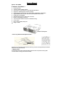
Press and push on the ‘arrow’ position rightward to open each HDD tray( see picture B-1)
b) LOCK
After HDD installed on the HDD tray, slide it into the frame and press the front handle
forward to lock the HDD tray on the frame( See picture B-2).
---Front Panel & Real View---
(See Picture C & D)
Picture C
C1—C6: HDD Tray
C8: HDD tray locker.
C7: LED indication ( Blue: Power on.
Accessing: Purple)
* Note: When the HDD is installed but it is not powered on, there is no LED indication.
D1: 4pin Power connector
D2 – D3: Cooling fan
D4 – D9 : SATA 7pin data port connectors
D10: HDD LED Switch( enable/disable )
HDD LED Switch Indication description:
(a)
When it is set to “ × “ position, the front LED does NOT light on or blinking while it is accessing [ In this case, the
(b)
When it is set to “ ○” position, it is lit on blue blinking while the HDD is being accessing. [ In this case, theHDD
(c)
The default setting for D10 (HDD LED Switch) is to “○” position (HDD LED Enable).
HDD will spin up when the system power is turned on ].
does not spin up until the SATA initial signal is received ].