1
2. Hardware Setup
Cable Connection
1. Important safety information regarding the placement of this
device is provided on page v. Please review it before
proceeding.
2. Make sure that power to all the devices you will be connecting
up have been turned off. You must unplug the power cords of
any computers that have the Keyboard Power On function.
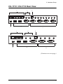
To set up your Master View CS-1772 / CS-1774 installation, refer to the
installation diagram on the following page, and do the following:
1. Plug your keyboard, mouse and monitor into the Console Ports located on
the unit's rear panel.
2. Plug your microphone and speakers into the Console microphone and
speaker jacks located on the unit's rear panel.
3. Using a KVM cable set (provided with this package), plug the custom
SPHD connector into any available CPU Port on the switch and plug the
accompanying microphone and speaker connectors into the CPU Port's
microphone and speaker jacks.
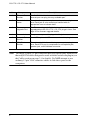
Note: 1. The connectors and jacks are color coded and marked with an
appropriate icon for easy installation.
2. Be sure that all the plugs are in the same CPU Port sockets (all in
Port 1, all in Port 2, etc.).
4. At the other end of the cable, plug the USB keyboard/mouse, USB hub,
video, microphone and speaker cables into their respective ports on the
computer.
5. Use Cat5 cable to connect any available ethernet port on the switch to the
computer's ethernet port.
Repeat steps 3 - 5 for any other computers you are connecting up.
6. Plug the cable from your external LAN source into any available ethernet
port on the switch.
7. Plug the power adapter that came with your switch into an AC power
source, then plug the power adapter cable into the switch's Power Jack.
8. Plug your USB peripherals into the USB hub section on the front panel.
9