1
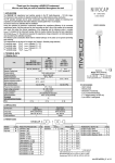
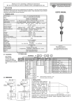
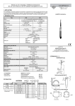
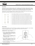
Thank you for choosing a NIVELCO instrument We are sure that you will be satisfied throughout its use 1. APPLICATION The vibrating rod is a mechanical resonant system excited and kept in resonance by an electronic unit. The medium to be measured, when reaching the vibration rod end, will damp the vibration. The change in vibration intensity is sensed by an electronic unit, which, upon the elapse of the delay time, actuates the output circuit. 2.0 TECHNICAL DATA 2.1. GENERAL SPECIFICATION USER’S MANUAL Standard 235 mm Version Probe length Parts protruding into the tank Pipe extended 0.3 … 3 m Cable extended 1 … 20 m Probe: 1.4571 Cable: PE coated 1.4571 Aluminium: Powder paint coated (R-300) Housing material Plastic: PBT fibre-glass reinforced, flame-retardant (DuPont) (R-400) RKH, RHH, RKR, RHR, RKK: 1 1/2" BSP Process connection RKN, RHN, RKL, RHL, RKC: 1 1/2" NPT Temperature ranges see TABLE2.1a and Derating diagram Max. pressure (absolute) 25 bar (2.5 MPa)** 6 bar (0,6 MPa)** Minimum medium density* 0.05 kg/dm3 (max. granular size: 10 mm) Response time Not vibrating ( covered) < 1.8 sec or 5 ±1.5 sec) (selectable) Vibrating ( free) < 2 sec or 5 ±1.5 sec Voltage version I: 16 ... 40V AC (50/60Hz) / 19 … 55V DC Supply voltage (universal) Voltage version II: 85 … 265V AC (50/60Hz) / 120 ... 375V DC Power consumption Voltage version I: ≤ 2.5 VA, 1.2W Voltage version II : ≤ 2.5 VA, 1.3 W 2 pcs. Pg16 for ∅8 to 15 mm cables; 2 pcs. plug-in type terminal block for max. Electrical connections 1.5 mm2 wire cross section Ingress protection IP 67 (NEMA6) MSZ EN 60529:2001 Electrical protection Class I. Explosion proof protection mark II 1/2D IP 65 (10 sensor/2D housing)(except version with plastic housing ) 1.56 kg 1.94 kg 1,56 kg (+1.4 kg/m) 1,94 kg (+1.4 kg/m) 1.56 kg (+ 0.6 kg/m) 1.94 kg (+ 0.6 kg/m) RKH-3, RKN-3 RKL-3, RKR-3 RKK-3, RKG-3 RHH-3, RHN-3 RHL-3, RHR-3 -30 °C … +110 °C +110 °C -30 °C … +50 °C -30 °C … +95 °C +95 °C -30 °C … +60 °C -30 °C … +160 °C +160 °C -30 °C … +35 °C +90 °C +85 °C +135 °C plastic housing aluminium housing Weight (with extension) 2.1A TEMPERATURE DATA Ex version Medium temperature range (category 1D) Max. surface temperature T Ambient temperature range (category 2D) Max. surface temperature T at process connection (cable gland) category 2D Manufacturer: NIVELCO Process Control Co. H-1043 Budapest, Dugonics u. 11. Phone: (36-1) 369-7575 Fax: (36-1) 369-8585 E-mail: [email protected] http://www.nivelco.com * may depend on friction and granular size of the medium ** in the presence of explosive atmosphere 0.8 ... 1.1 bar 2.2 Output versions RELAY SOLID STATE Output R--1 R--2 R--5 R--6 SPDT (potential free) R--3 R--4 R--7 R--8 SPST (electronic) Output rating 250 V AC, 8A, AC 1 350 mA/50V pick Output protection - Overvoltage, overcurrent and overload protection Voltage drop (switched of state) - < 1.7 V @ 350 mA Residual current (switched on state) - < 10 µA Version Derating diagram F = 445 N M = 85 Nm RKKRKCF = 45 kN Figure 1 Torque and force − − − − − 35 20 0 RKRRHRRKLRHLM = 85 Nm 2.3 ACCESSORIES TA [°C] 60 50 -30 RKHRHHRKNRHN- 0 50 75 100 110 Uer’s manual Warranty card 2 pcs. 3-pole terminal block 1 ½ " sealing , for BSP only 2 pcs. Pg 16 cable gland 160 TM [°C] -30 Figure 2 Ambient temperature (TA) versus medium temperature (TM ) 2.4 ORDER CODE NIVOCONT R VERSION Standard High Temp. CÓDE K H* PROCESS CONN. 1 ½ " BSP 1 ½ " NPT * only for standard and pipe extended version STANDARD H N CODE PIPE R L CABLE K C — HOUSING Alu cast Plastic CODE 3 4 — PROTRUSION LENGTH 235 mm 0.5 … 3 m 1 … 20 m STANDARD 02 — — CÓDE PIPE CABLE — — 05…30 — — 01…20 SUPPLY / OUTPUT/ Ex 85-265 V AC / 120-375 V DC / relay 16-40 V AC / 19-55 V DC / relay 85-265 V AC / 120-375 V DC / solid state 16-40 V AC / 19-55 V DC / solid state 85-265 V AC / 120-375 V DC / relay / Ex 16-40 V AC / 19-55 V DC / relay / Ex 85-265 V AC / 120-375 V DC / solid state / Ex 16-40 V AC / 19-55 V DC / solid state / Ex CODE 1 2 3 4 5 6 7 8 2.5 DIMENSION 5. ELECTRICAL CONNECTION STANDARD PIPE EXTENDED A B 2 x Pg16 2 x NPT ½" R-300 100 89 120 R-400 93 89 118 A B C Overload LED 250VAC 8A/AC1 N L1 1 2 3 4 5 6 50V 350mA 2,7k N L1 1 2 3 4 5 6 IN COM +24V N 161 C C L=1000-20000 L=500-3000 B 161 A B Status LED BSP 1 ½" NPT 1 ½" BSP 1 ½ " NPT 1 ½" 161 235 C 2 x Pg16 2 x NPT ½" BSP 1 ½ " NPT 1 ½" A B B C 2 x Pg16 2 x NPT ½" Status LED A C A CABLE EXTENDED T L1 PE NO C NC N L1 PLC PE PE Figure 3 Figure 7 Electrical connection of relay output version 3. INSTALLATION Prior to installation, it is advised to check the switching function for proper adjustment on a sample quantity of material (see Calibration). The unit may not work with mediums within the specified density range but having very large size of granules or extremely little friction. B C A Status LED B C Overload LED WARNING! Handle the device with great care, especially the sensing probe. Any impact on the sensing probe may ruin its resonance system. A protective shield should be installed (see Figure 6) if the probe is exposed to falling material or a excessive mechanical load. Screw in the device by its hexagon neck. After screwing tight the process connection, the housing can be rotated (max. 300°), to adjust the cable gland to the required position. It might be necessary to install the device at an offset level position relative to the switching level actually required taking into account caving or arching of the material in the silo (see Figure 4) High level indication Low level indication A Status LED Figure 8 Electrical connection of a optocoupled sink input to a solid state output version supplied from a AC line Overload LED 50V 350mA 2,7k N L1 1 2 3 50V 350mA 2,7k N L1 1 2 3 4 5 6 4 5 6 Device to be controlled +5 V N 5W IN N L1 24 V AC 50 Hz L1 PE GND PE Figure 9 Electrical connection of a logical voltage input to a solid state output version supplied from a AC line Figure 10 Electrical connection of a load to a a solid state output version supplied from a AC line 5.1. OPERATING DIAGRAM POWER PROBE FAIL-SAFE MODE LOW LED GREEN NOT VIBRATING (COVERED) With powder level detection device should be installed at an inclination exceeding the angle of repose (or, in case of high level detection vertically), to prevent powder deposition on vibrating rod that might substantially reduce the self-cleaning effect. Also avoid mounting the rod in a recess (see Figure 5) RED LOW RED HIGH GREEN L30x30x3 Remove the top cover of the housing to access the connection terminals and adjusting switches. Do not remove the wire form terminal pin 1 (Figure 7) because it is an internal connection. For grounding the unit use the PE grounding screw terminal PE. After proper installation and the electrical connection, established the device is ready for operation. The switched-on state is indicated by the lighting of the LED. The DENSITY (switch A) switch is to be set in accordance with the density of the material: • LOW position, recommended for loose and light materials with density below 0.1 kg/dm3 represents small energy and amplitude of vibration as well as great sensitivity of detection. • HIGH position, recommended for (thick and heavy) materials with density over 0.1 kg/dm3 represents vibration with great energy and amplitude and small sensitivity of detection. To obtain FAIL SAFE alarm (switch C), use the de-energised or open state of the output as an alarm, thus a power breakdown will also be considered as alarm (see Table below). The delay (switch B) is to be selected to comply with requirements of the process control technology the units is used for. Note: The instrument may be damaged via switches by electrostatic discharge (ESD), thus the precautions commonly used to avoid ESD is to be applied. 6 5 4 6 5 4 6 5 4 6 LOW or HIGH NOT LIT 5 4 6 DE-ENERGISED 5 ON 6 2,7 k 5 4 OFF 6 2,7 k 5 4 OFF 6 2,7 k 5 4 ENERGISED FAILS 2,7 k 4 DE-ENERGISED VIBRATING (FREE) 4.ADJUSTMENT 4 6 DE-ENERGISED ON Figure 5 Figure 6 In case of tanks that are likely to be exposed to intense vibrations, necessary provisions shall be made for damping the vibrations acting on the device (e.g. vibration damping inserts made of rubber have to be applied). 5 ENERGISED HIGH Figure 4 SOLID STATE OUTPUT RELAY ON 6 2,7 k 5 4 OFF 5.2. The regulations of EN 50281-1-2 European Standard must be fulfilled (temperature, dust layer thickness etc.) 6. MAINTENANCE, REPAIR The NIVOCONT R-300/R400 series devices do not require maintenance on a regular basis. In some instances, however, the vibrating section may need a cleaning from deposited material. This must be carried out gently, without harming the vibrating section of the vibrating rod. Repairs during or after the guarantee period are effected at the Manufacturers. The equipment sent back for repairs should be cleaned or neutralised (desinfected) by the User. 7. STORAGE CONDITIONS Ambient temperature: -35 to +60°C Relative humidity: max. 98 % 8. WARRANTY All Nivelco products are warranted free of defects in materials or workmanship for a period of two years from the date of purchase. Repairs under guarantee are carried out at the Manufacturer's premises. The Purchaser is liable for costs of dismantling and re-installation as well as transport costs. Nivelco shall not be liable for misapplication, labour claims, direct or consequential damage or expense arising from the installation or use of equipment. rkh3011a0600h_03 2002, August Nivelco reserves the right to change technical specifications without notice