1
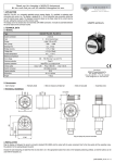
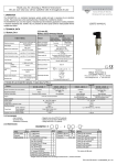
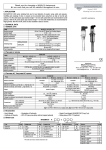
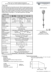
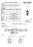
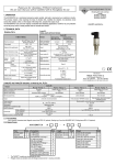
Thank you for choosing a NIVELCO instrument We are sure that you will be satisfied with it throughout its use 1. APPLICATION NIVOTRACK MT-2 series float type magnetosrictive level transmitter is a two-wire precision measuring instrument for clean liquids both in normal and hazardous location. These instruments re quire minimum maintenance since the float is the only moving part. USER’S MANUAL 2. TECHNICAL DATA Insertion length L 0.5 m … 3.7 m according to the Order Codes maximum: up to the bumping point of the float minimum: 0,6 x Insertion length maximum: 0,4 x Insertion length 2,5 MPa (25 bar) for steel floats ; 0,3 MPa (3 bar) (20°C) for plastic floats min. 0.7 g/cm3 with float 52 mm ; min. 0.5 g/cm3 95 mm Range Zero offset Process pressure (maximum) Medium density - 40 °C…+130 °C * Medium temperature Ambient temperature Float size / material Material of wetted parts Output Accuracy Linearity Repeatability Maximum load resistance Maximum output / Fault indication value Damping Supply voltage Ex protection Ex power supply Electric protection Ingress Protection Process connection Electric connection Enclosure Mass PP: - 20 °C…+80 °C * PVDF: - 20 °C…+130 °C * Ex : - 40 °C… +70 °C - 40 °C … +70 °C * 52x59 mm / 1.4571 95 mm / 1.4571 76x87 mm / PP or PVDF Stainless steel : 1.4571(DIN) PP or PVDF float: see Order Codes Normal operation 4 mA bottom… 20 mA top Reverse operation 20 mA bottom… 4 mA top (on special request) ±0.04% or 1 mm 0.035% or 0.8 mm 0,01% or 0,4 mm Rt = ( Ut -10.5 V) / 0.02 A Ut = power supply voltage 24mA 1 sec, 5 sec adjustable 10.5 … 36 V DC EEx ia IIB T5 Umax = 28.4 V DC Imax = 99 mA Pmax = 0.67 Watt III. Protection Class IP 67 According to the order codes 2 x Pg 16 and 2 x 1/2" NPT thread, shielded cable: 0,75 ... 1.5 mm2 Powder paint coated aluminium 2.2 kg + guiding tube 0.35 kg/m Manufacturer: Nivelco Process Control Co. H - 1043 Budapest, Dugonics u. 11. Telephone: (36-1) 369-7575 Fax: (36-1) 369-8585 E-mail: [email protected] http://www.nivelco.com * See derating diagram under 3.! 2.1 2.2 ORDER CODES ACCESSORIES NIVOTRACK User’s Manual Warranty sheet 2 x Pg 16 cable gland, Sealing ring for connection with BSP thread only (klingerit oilit) Model Code Transmit A 1 1/2” BSP1.4571 2” BSP 1.4571 1” NPT 1.4571 B C D 1m 2m 3m 1 1/2” NPT1.4571 2” NPT 1.4571 1” BSP sliding sleev 1 1/2” BSP sleeve 2” BSP sleeve 1” NPT sleeve E G H J K L 1 1/2” NPT sleeve 2” NPT sleeve DN 80 DN 100 DN 125 M N P R S 1” BSP 2.3 DIMENSIONS - 2 Insertion lenrth 0m Process connection T M 1.4571(DIN) Code Note: - 0 Insertion lenrth 0m 1 2 3 Code Code Version / Ex 0 Steel ball float Code 0.1 m 0.2 m 0.3 m 1 2 3 Steel cylindrical float 52 mm Steel ball float 95 mm Ex Steel cylindrical float 52 mm Ex 2 5 6 0.4 m 0.5 m 0.6 m 0.7 m 0.8 m 0.9 m 4 5 6 7 8 9 PP cylindrical float 76mm , flange PP PVDF cylindrical float 76mm, flange PP PVDF cylindrical float 76mm, fl. A38+PVDF PP cylindrical float 76mm , flange PP Ex PVDF cylindrical float 76mm, flange PP Ex PVDF Cylindr float 76mm, fl. A38+PVDF Ex A B C E F G 95 mm 1 1. Reverse operation on request (20 ... 4 mA) 2. Not all code variations can be selected 3. INSTALLATION 20 mA max. meas. range 4 mA ** UP inactive track ** UP Benyúlási hossz 0,5 - 3,7 m 4 mA ** insertion length 0.5 - 3.7 m inactive track max. meas. range ** ** According to the order code 20 mA The NIVOTRACK MT-2 should be °C located in an area, which allows easy 70 access for service, calibration and monitoring. Accuracy of the measurement will be affected by 45 waves on the surface or excessive vibration. Therefore the instrument should be located away from the inlet and outlet as far as possible. The 70 130 °C process fluid should be free of any Medium temperature suspended solids or material that could stick between the float and the guide rod. If used at temperatures in exess of 70 °C the maximum ambient temperature allowed will be in accordance with the derating diagram. Ambient temperature 2x1/2"NPT insertion length 0.5 - 3.7 m 2x1/2"NPT ~335 2xPg16 ~337 2xPg16 ~156 89 ~156 89 operation. The only difference is that the 4 mA in the top position should be set by the potentiometer SPAN and that the 20 mA in the bottom position should be set by the potentiometer ZERO. Adjustment of damping (Jumper JP3) Jumper JP3 allows for the adjustment of the damping time. This jumper is factory set between pins 1 2 for 1 second. Damping Suggested opening greater than ∅ 54 mm 1s JP3 position 5s 1s 5s 1s 5s Shaft UP Lnévl. The unit should be protected against heat radiation! NIVOTRACK MT_-2 series is offered with a variety of process connections. The process connection on the tank and its opening should be arranged so that the float can be inserted. Should it not be possible, the float should be removed from the sensor shaft. After inserting the shaft, the float should be pulled onto the guide tube inside the vessel. The word UP etched on the float is to ensure mounting the float in correct position. To complete procedure, the retaining pin should be inserted into its hole and legs bent. Note: before installation it is advisable to perform a preliminary operational check similar to the procedure described in the Calibration section. 2 6 1 5 liquid 1S 5S JP2 LED J5 (-) 3 2 1 4. WIRING After unscrewing and removing the housing cover from the unit the cable should be pulled through the conduit opening. The unit contains CMOS components, which can be damaged by static electricity. Therefore the shielding of the cable should be connected to the ground screw first. After the shield is grounded, the (+) wire and (–) wire of the terminal J1 should be connected. Is the shield also grounded at the power supply an equaliser cable should be applied between the two ground screws. 5.1. POWER SUPPLY FOR EX PROOF UNITS The unit can be connected to a current loop with duly certified EEx ia IIB power supply and with technical data according to the Technical Data. Ex Terminal J1 Galvanical isolation 230V AC U max = 28.4 V DC I max = 99 mA Pmax = 0.67 W C i = 150 nF L i = 1.2 mH + 2 Ex + 1 . 5. SETUP PROCEDURE, CALIBRATION After power up the unit is fully operational. Factory Setting Operation mode: in accordance with the order (normal or reverse). Range: maximum or in accordance with the order. Damping: 1s Operating mode selection (Jumper J1) Direction of the output change assigned to the level change can be the same or reversed. Note: Jumper J1 is factory set. It must not be changed in the field! Normal operation 2 JP1 position 1 Low level High level 6 The unit does not require routine maintenance, however the shaft may need occasional cleaning to remove surface deposits. Repairs will be performed at the manufacturer premises. Units returned for repair should be cleaned or desinfected by the customer. 5 7. STORAGE CONDITIONS Reverse operation 6 2 5 1 4 mA 20 mA 20 mA 4 mA Ambient temperature: -30°C … +60 °C Relative humidity: max. 98% 8. WARRANTY Local current meter (Jumper JP2). Jumper JP2 allows for the connection of an auxiliary current meter: Move Jumper JP2 from pins 1-2 to pins 2-3. 3 - 2 1 3 2 6. MAINTENANCCE AND REPAIR 1 The (yellow) LED will illuminate indicating possibility of the measurement. Connect the meter J4 (positive) and J5 (negative), and the LED will go out. Move the Jumper JP2 back to pins 1-2 after measuring the current. Calibration Normal operating mode Move the float to the desired top position for the 20 mA output. Adjust SPAN: clockwise to increase and counter-clockwise to decrease the output to 20 mA ±0.01 mA. Move the float to the desired bottom position for the 4 mA output. Adjust ZERO: clockwise to increase and counter-clockwise to decrease the output to 4 mA ±0.01 mA. Repeat steps 1 and 2 several times until the outputs at the set points remain ±0.01 mA. Reverse operating mode: It is the same procedure as with the normal Nivelco provide a warranty for the period of 2 (two) years. Repairs under warranty are performed at the Manufacturer's premises; costs of dismantling, reinstalling or shipping are borne by the Customer. Claims for guarantee are not valid in respect of failures due to abnormal usage, breakage, disaster, or incompetent installation or usage. mtc2092a0601h 2002.01.02 Technical specification may be changed without notice.