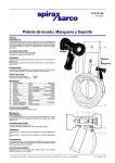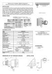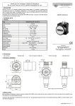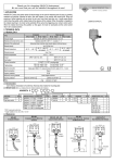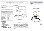
1
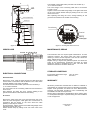
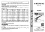
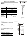
Thank you for choosing a NIVELCO instrument.
We are sure that you will be satisfied throughout its use.
APPLICATION
The NIVOPOINT MR series of magnetic float level switches are applicable for point level
switching (high or low) or for alarm (overfill, empty) in liquids.
In case of liquids containing metal particles protect the device by using a magnetic filter.
USER’S MANUAL
2. TECHNICAL DATA
Model
MR _ _ _
Probe length
MR _ _ _ Ex
0,25...3 m
Material of wetted parts
Max. process pressure
Stainless steel DIN 1.4571 / BS 316Ti)
2,5 MPa (25 bar) (at 20°C)
min. 0,7g/cm3
Medium density
Medium temperature range
-40°C to +150°C
Ambient temperature range
-40°C to +100°C
Output
1 to 5 pcs. NO or NC reed relays
Switching rate
120 W / VA, 250 V AC, 3 A /reed relay, max. 9 A
Switch differential
< 10 mm
Distance between switch points
Electrical connection
min. 110 mm
Screw terminals in housing with
Pg 16 for cables ∅7 to ∅14 mm
Screw terminals in housing with
Pg 16 for cables ∅9,5 to∅10
Wire cross section: 0,5 to 2,5 mm2
Process connection
1" or 2" BSP/NPT
Sealing material
Klingerit 400
Electrical protection
Class I.
Mechanical protection
IP 65
Dimension of the housing
110 x 80 x 65 mm
Certificate for Ex versions
−
EEx d IIC T4-T6
Manufacturer:
0.4 kg + 0.3 kg/m
0.45 kg + 0.3 kg/m
NIVELCO Process Control Co
DIMENSIONS
86
A magnetic float moving alongside the protection tube tracking
the level, is activating the reed relays incorporated the tube. After
passing of the float, the reed relays will retain their output state.
The device is capable of direct switching a load within its
specification.
The switch point adjustment gland must not be
loosened in tanks under pressure.
L2
L1
Ø 12
min.
80
WARNING!
min.
110
Use a wrench at the hexagon neck to hold the device against
rotation while loosening and tightening the nut.
Ln=500-3000
Ø 52
L4
1” or 2”
L5
min.85
S=55 or 70
L3
– loosen the nut above the hexagon neck
– turn the housing as well as adjust the reed relays vertically to
the required position
– tighten the nut
± 25mm (adjustment)
min.
110
After fastening, the position of the cable gland can be rotated
±180° as well as the position of reed relays can be set ±25mm.
Both adjustments can be done by the switch point adjustment
gland, as follows:
155-205
The device should be mounted in vertical position via its process
connection and handled with care to avoid any damage or bend
of the protection tube during transportation or installation.
18 or 24
INSTALLATION
Pg16
min.
110
OPERATION
H-1043 Budapest, Dugonics u. 11.
Tel.: (36-1)-369-7575
Fax: (36-1)-369-8585
E-mail: [email protected] http://www.nivelco.com
min.
110
Weight
160 x 80 x 65 mm
Figure 1.: Dimensions of the standard version
99
The terminal of the lowest switch point has to be number by 1.
„C” is common terminal.
The cross section of the connecting cable has to be between
0.5 and 2.5 mm2.
Tighten screws of the cable fixing bridge on the gland and screw
up the cover. Fasten retainer clamp by setting it into one of the
notch of the cover.
After replacing and fixing the cover, arrange earthing at the
ground screw located on the outside of the housing.
155-205
Pg16
± 25mm (adjustment)
Ground screw
L4
min.
110
18 or 24
1” or 2”
L5
min.85
S=55 or 70
LEVEL
Ln=500-3000
L2
min.
110
L3
min.
110
Ø 52
1 2 3 4 5 C
NO
Marking
of relay type
min.
80
L1
min.
110
NC
Ø 12
Terminal
Figure 3.: Housing with removed cover
Figure 2.: Dimensions of the Ex version
ORDER CODE
MAINTENANCE, REPAIR
NIVOPOINT MR
PROCESS CONNECTION CODE
G1“
A
G2“
C
NPT 1“
D
NPT 2“
G
SWITCH POINT CODE
1
1 pc. NO/NC
2
2 pc. NO/NC
3
3 pc. NO/NC
4 pc. NO/NC
4
5 pc. NO/NC
5
-
-
LENGTH CODE
0m
0
1m
1
2
2m
3m
3
FLOAT
Ø 52 x 52
Ø 52 x 52/Ex
CODE
3
7
LENGTH CODE
0m
0
1
0,1 m
…
…
0,8 m
0,9 m
The instrument does not require regular maintenance. In some
instances, however, the sensor probe may need occasional
cleaning to remove surface deposits. This must be carried out
gently, without harming the sensor probe.
Repairs during or beyond the guarantee period are carried out
solely by the manufacturer. Equipment sent back for repair
should be cleaned or sterilised by the User. The User must
declare that the above has been carried out.
8
9
STORAGE CONDITIONS
ELECTRICAL CONNECTIONS
Standard model
Remove the cover, pass the wires through the cable gland and
connect them in accordance with the sketch on the cover where
the state (NO/NC) of the relays is marked.
The terminal of the lowest switch point has to be number by 1.
„C” is common terminal.
The cross section of the connecting cable has to be between 0.5
and 2.5 mm2.
After replacing and fixing the cover, arrange earthing at the
ground screw located on the outside of the housing.
Ex version
Remove the clamp, fixing the cover and screw down the cover.
Pass the wires through the cable gland and connect them in
accordance with the sketch on the cover where the state
(NO/NC) of the relays is marked.
Arrange earthing. Tighten screws of the cable fixing bridge on the
gland and screw up the cover.
Fasten retainer clamp by setting it into one of the notch of the
cover.
Environment temperature range:
Relative humidity:
-25°C to +60°C
max. 98 %
WARRANTY
All Nivelco products are warranted free of defects in materials or
workmanship for a period of two years from the date of purchase.
Repairs under guarantee are carried out at the Manufacturer's
premises. The Purchaser is liable for costs of dismantling and
re-installation as well as transport costs.
Nivelco shall not be liable for misapplication, labour claims, direct
or consequential damage or expense arising from the installation
or use of equipment.
mra1053a0600h_03
06.06.2000.