1
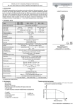
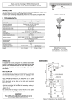
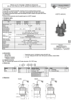
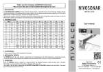
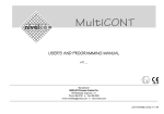
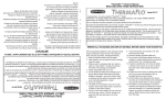
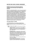
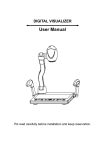
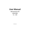
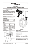
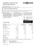
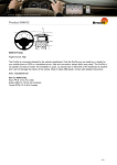
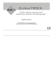
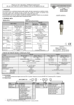
Thank you for choosing a NIVELCO instrument.
We are sure that you will be satisfied throughout its use!
NIVOCAP
1. APPLICATION
The NIVOCAP CK capacitance level switches operate in the RF (radio-frequency) ~ 130 kHz range.
The instrument is less sensitive to deposits provided by the so-called reference probe construction.
The RF operation principle and the probe construction make the instrument suitable for detecting level
of powders and solid materials with relative dielectric constant grather than 1.5 and liquids.
The device needs to be calibrated after the installation.
During the operation the electronics continuously evaluates the capacitance difference of the connected
measurement probe. Until the probe and its close surronding are free in the air (the medium to be measured
don’t reach the probe) the minimal capacitance of the measuring and the reference probe is constant
(εrelative=1) compared to the instrument housing. When the medium reaches the probe the basic capacitance
will increase (εrelative>1). The electronic measures this capacitance change compared to an initial capacitance
value recorded by the calibration procedure.
The reference probe construction allows that the material build-ups on the probe can be ignored preventing
false switching.
The measurement can be done in four ranges (see Chapter 4: Sensitivity range selection)
4th sensitivity range: 0.5 pF, εrelative = between 1.5 – 2.0
3rd sensitivity range: 2.5 pF, εrelative = between 2.0 – 4.0
2nd sensitivity range: 8.0 pF, εrelative = between 4.0 – 7.0
1st sensitivity range: 18 pF, εrelative > 7.0
2. TECHNICAL DATA
2.1 GENERAL DATA
STANDARD
CK(D,G,M,P,H,N)-1-1
CM(D,G,M,P,H,N)-1-1
TYPE
Probe length
Material of wetted parts
Housing material
Process connection
Ambient temperature
Medium temperature range
Medium temperature range for
high temperature types
Max. process pressure
Response time (selectable)
Supply voltage (universal)
Power consumption
Ingress protection
Electrical protection
Ex marking
(only with aluminium housing)
Mass
ROD
EXTENDED
CKR-1-1,
CKL-1-1
CMR-1-1
CML-1-1
0.7 … 3 m
CABLE
EXTENDED
CKK-1-1
CKC-1-1
300, 400, 500-600 mm
1.4571
Paint coated aluminium
As per order code
-30 ºC…+65 ºC
-30 ºC…+110 ºC
1 … 10 m
1.4571 / antistatic PP
Manufacturer:
NIVELCO Process Control Co.
H-1043 Budapest, Dugonics u. 11.
Tel.: (36-1) 889-0100
Fax: (36-1) 889-0200
E-mail: sales @nivelco.com www.nivelco.com
-25 ºC…+90 ºC
-30 ºC…+220 ºC
-
3 bar (0.3 MPa)
3 bar (0.3 MPa)
2.3 ACCESSORIES
−
−
−
−
−
−
0.15 – 15 sec
20…255 V AC/DC
≤ 2.5 VA / 2 W
IP67 (NEMA6) EN 60529:2001
Class I. (to be grounded!)
….
… kg
… kg
User’s manual,
Warranty Card,
Declaration of Conformity,
2 pcs. 3-pole terminal blocks,
1 ½ " klingerit sealing, for BSP only
2 pcs. M20x1.5 cable glands
… kg
2.2 SPECIAL DATA
OUTPUT DATA
Output type
Output rating
Output protections
2.4 ORDER CODES
VERSION
Standard
High temp.
CODE
K
M
RELAY
C-1-1
SPDT (potential free)
250 V AC, 8A, AC 1
—
NIVOCAP C
PROBE TYPE / PROCESS CONN.
Standard ¾” BSP
Standard ¾” NPT
Standard / 1” BSP
Standard / 1” NPT
Standard / 1½” BSP
Standard / 1½” NPT
Cable extended / 1½” BSP
Cable extended / 1½” NPT
Rod extended ¾” BSP
Rod extended ¾” NPT
Rod extended / 1” BSP
Rod extended / 1” NPT
Rod extended / 1½” BSP
Rod extended / 1½” NPT
CODE
D
G
M
P
H
N
K
C
E
F
V
Z
R
L
SOLID STATE
C-1-3
SPST (electronic)
50V, 350 mA
Varistor
- 1
HOUSING
Aluminium
CODE
1
CODE
0
1
2
3
4
5
6
7
PROBE LENGTH
CODE
0
0m
1
1m
2
2m
3
3m
4
4m
5
5m
6
6m
7
7m
0m
0.1 m
0.2 m
0.3 m
0.4 m
0.5 m
0.6 m
0.7 m
POWER SUPPLY / OUTPUT / EX
20-255 V AC/DC / Relay
20-255 V AC/DC / Electronic
20-255 V AC/DC / Relay / Ex tD
20-255 V AC/DC / Electronic / Ex tD
CODE
1
3
5*
7*
8
8
8m
0.8 m
9
9
9m
0.9 m
A
10 m
* Under approval!
Cable extended types: from 1 m up to 10 m, with 0.5 m steps!
Rod extended types: from 0.7 m up to 3 m, with 0.1 m steps!
Standard types: CK-103, CK-104, CK-105, CK-106
ckm1051a0600h_01 ♦ 1/4
2.5 DIMENSIONS
STANDARD
ROD EXTENDED
CABLE EXTENDED
HIGH TEMPERATURE VERSION
WITH STANDARD PROBE
HIGH TEMPERATURE VERSION
WITH ROD EXTENDED PROBE
CKM-1-1, CKP-1-1
CKR-1-1, CKL-1-1
CKK-1-1, CKC-1-1
CMM-1-1, CMP-1-1
CMR-1-1, CML-1-1
119
2 pcs M20 x 1.5
2 x NPT 1/2"
2 pcs M20 x 1.5
2 x NPT 1/2"
2 pcs M20 x 1.5
2 x NPT 1/2"
SW 55
SW 55
1 1/2" BSP
or NPT
1 1/2" BSP
or NPT
Ø28
1 " BSP
or NPT
Ø20
Ø16
Ø100
Ø100
SW 41
1" BSP
or NPT
Ø20
L
L
Ø20
SW 55
1 1/2" BSP
or NPT
Ø28
Ø16
Ø20
434
L
L
Ø28
L
Ø16
Ø8
~89
221
SW 41
2 pcs M20 x 1.5
2 x NPT 1/2"
~89
~89
119
150
2 pcs M20 x 1.5
2 x NPT 1/2"
~89
218
~89
Ø20
Ø8
Ø8
Ø16
434
434
Ø16
Ø8
Ø8
3. MOUNTING
Prior to installation, it is advised to check the switching function for proper adjustment on a sample quantity of material.
WARNING! Handle the device with great care, especially the sensing probe. Any strong impact or bending on the sensing probe may damage the device.
A protective shield should be installed (see the figure) if the probe is exposed to falling material or excessive mechanical load.
Screw in the device by its hexagon neck. After screwing tight the process connection, the housing can be rotated (max. 300°), to adjust the cable gland to the required
position.
It might be necessary to install the device at an offset level position relative to the switching level actually required taking into account caving or arching of the material in
the silo.
High level indication
Low level indication
RECOMMENDED
NOT RECOMMENDED
In case of powder level detection the device should be installed that the
inclination of the side mounted probe should be greater than the angle of repose
(or, in case of high level detection vertically), to prevent powder deposition on
the probe that might cause false switching. Also avoid mounting the unit near to
recess or near to any surface that facilitate build-up forming.
In case of tanks that are likely to be exposed to intense vibrations the electronic output versions should be applied.
ckm1051a0600h_01 ♦ 2/4
4. INSTALLATION, PUTTING INTO OPERATION
4.1. BASIC CONCEPTS
Response (delay) time adjustment potentiometer: DELAY
The instrument senses the material when is reaches the probe and the switching is performed only after a selected time interval (0 sec – 15 sec). This delay time can be
user selected by thy delay time potectiometer between 0 sec and 15 sec. The delay time can be increased by turning the potectiometer to the right.
When the material sets the probe free the switching is also performed only after the selected time delay.
If the „material presence” or „material non-presence” state changes during the delay time, the delay time starts again.
Sensitivity fine adjustment potentiometer: FINE SENS
Further fine sensitivity adjustment can be done within the selected sensitivity range by a potectiometer. The sensitivity can be increased by turning the potectiometer to the
right.
Sensitivity range selecting push button: SENS
This push button allows to select the required sensitivity range. To change over the ranges press the button repeatedly.
Fail-safe switch: F – S (H – S)
The low and high fail safe mode can be selected by the fail-safe switch.
The fail-safe indication is performed by de-energized state relay output (see the operation diagram table)
High Fail – safe:
The probe senses the material, but the relay reamains in de-energized state similarly to in case of power failure.
Low Fail – safe:
The probe not senses the material, but the relay reamains in de-energized state similarly to in case of power failure.
4.2. PUTTING INTO OPERATION
Remove the housing cover to access the connection points and the control elements.
The output should be protected by a 2A time delay fuse in case of electronic output versions.
The instrument should be configured and calibrated after the installation and the wiring.
ATTENTION! The instrument may be damaged by electrostatic discharge (ESD) via its terminal, thus apply the precautions commonly used to avoid electrostatic
discharge e.g. by touching a properly grounded point before removing the cover of the enclosure.
The RF-capacitance level switch will function incorrectly if:
− The relative dielectric constant of the measured medium is under 1.5.
− There is a connection bridge between the probe and the tank wall.
− The instrument has improper grounding.
− The insulation on the probe is damaged.
− The probe is not properly assembled.
4.3. CALIBRATION
Calibration push button: CAL
The calibration should be performed after the installation. The instrument housing should be grounded. Press the CAL button for a few seconds.
The blue LED will light first, then it will be blinking and then the LED will show the colour of the relating operation state as indicating the successful calibration procedure
The calibration procedure contribute that after the installation the capacitance change occurring in the tank will be learned by the electronics and considered as initial
reference capacitance value.
If the unit is installed in hazardous (Dust Ex) environment where the housing cover is not allowed to remove when the unit is energized, the calibration can be done without
removing the housing cover by a magnet. The supplied permanent magnetic screw allows performing the calibration procedure through the aluminium housing.
This case the status LED will blink blue during the calibration. All the other configuration settings (Sensitivity range selection, Sensitivity fine adjustment, Delay adjustment,
Fail-safe operation mode selection and switching the Magnetic Calibration switch to ON state) should be carried out outside the hazardous environment (e.g. in the control
room) before mounting the instrument.
The calibration can be performed multiple times.
ckm1051a0600h_01 ♦ 3/4
5. WIRING
Delay potentiometer
Sensitivity potentiometer
Sensitivity range button
Operation switch
Calibration switch
Status LED
Power supply
Relay output
Electronic output
Wiring of relay and electronic output versions
5.1 OPERATION DIAGRAM
POWER
OPERATION
FAIL-SAFE MODE
STATUS LED
Hign level
GREEN BLINKING
Low level
5
4
6
5 and 4 OFF
5
4
6
5 and 4 OFF
5
4
6
5 and 4 ON
DE-ENERGISED
LOW
HIGH
or
LOW
5 and 4 ON
ENERGISED
LOW
RED BLINKING
__
4
6
DE-ENERGISED
HIGH
GREEN LIGHT
OFF
5
SOLID STATE OUTPUT
ENERGISED
HIGH
RED LIGHT
ON
RELAY
NOT LIT
5
4
6
5 and 4 OFF
DE-ENERGISED
6. MAINTENANCE AND REPAIR
The NIVOCAP CK-100 series devices do not require maintenance on a regular basis. In some instances, however, the probe may need a cleaning from deposited
material. This must be carried out gently, without harming the probe.
Repairs during or after the warranty period are effected at the Manufacturers. The equipment sent back for repairs should be cleaned or neutralized (disinfected) by the
User.
7. STORAGE
Ambient temperature: -35 ... +60°C
Relative humidity: max. 98 %
8. WARRANTY
NIVELCO provides warranty of 3 (three) years in compliance with details described in the Warranty Card.
ckm1051a0600h_01.doc
March 2013.
NIVELCO reserves the right to change technical data without notice.
ckm1051a0600h_01 ♦ 4/4