1
NV-500 Industrial VDSL2 Bridge with DIP Switch USER’S MANUAL Ver. A6
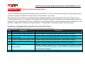
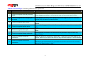
3.2 Front Indicators
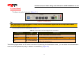
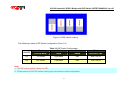
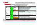
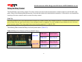
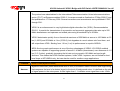
The bridge has Eight LED indicators. The following Table shows the description. (Table 3-3)
Table 3-3 LED Indicators Description and Operation
LED
PWR
(Power LED)
Color
Green
ETHERNET 1-4
Green
(Ethernet LED)
Status
Descriptions
On(Steady)
Lights to indicate that the VDSL2 bridge had power
Off
The device is not ready or has malfunctioned.
On(Steady)
The device has a good Ethernet connection.
Blinking
The device is sending or receiving data.
Off
The LAN is not connected.
CO
(CO LED)
Green
On(Steady)
Indicate the VDSL2 bridge is running at CO(Master) mode.
CPE
(CPE LED)
Green
On(Steady)
Indicate the VDSL2 bridge is running at CPE(Slave) mode.
On(Steady)
The Internet or network connection is up.
Blinking slowly
The CO device is auto-detecting CPE device.
Blinking fastly
1. The CO device has detected a CPE device and ready to connect.
2. The device is sending or receiving data.
Off
The Internet or network connection is down or has malfunctioned.
LINK
(VDSL LED)
Green
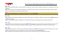
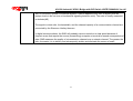
Note:
Two Bridges connection may take within 3 minutes is normal, due to NV-500 to establish a link mechanism is auto-negotiation, with
detects and calculate CO and CPE both PBO and PSD level as well as noise level ....and other argument etc. for getting a better
connection.
21