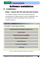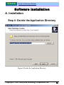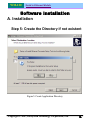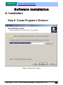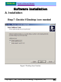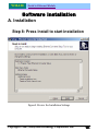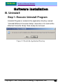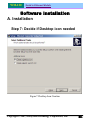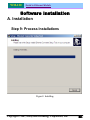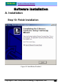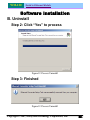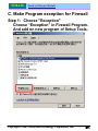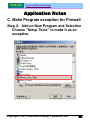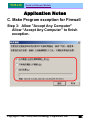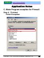
1
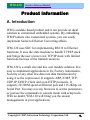
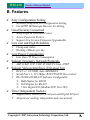
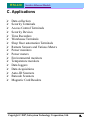
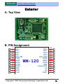
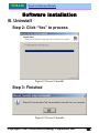
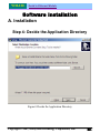
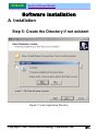
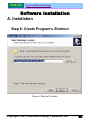
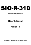
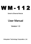
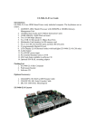
WM-120 Serial to Ethernet Module WM-120 Serial to Ethernet Module User Manual Version 1.0 Infosystem Technology Corporation, Ltd. WM-120 Serial to Ethernet Module Index 1. Disclaimers .......................... 1. A. Warranty ......................... 2. B. Trademark ........................ 2. 2. Product Information ....................... 3. A. Introduction ........................ 3. B. Features ......................... 4. C. Applications ....................... 5. 3. Exterior ........................... 6. A. Top View ......................... 6. B. PIN Assignments ...................... 6. C. PIN Descriptions ...................... 7. 4. Software Installation ....................... 8. A. Install ......................... 8. - Step 1: Insert the CD and click the button ........... 8. - Step 2: Click the Link of the Page ............. 9. - Step 3: Press Next to Continue .............. 10. - Step 4: Decide the Application Directory ........... 11. - Step 5: Create the Directory if not existent .......... 12. - Step 6: Create Program’s Shortcut ............. 13. - Step 7: Decide if Desktop icon needed ............ 14. - Step 8: Press Install to start installation ........... 15. - Step 9: Process Installations ............... 16. - Step 10: Finish Installation ................ 18. B. Uninstall ......................... 18. - Step 1: Uninstall Ethernet Converter ............ 18. - Step 2: Processing ................... 19. - Step 3: Finished .................... 19. WM-120 Serial to Ethernet Module Index 5. Configuration ......................... 20. A. By Browser ....................... 20. - Step 1: Ready to login.................. 20. - Step 2: Configure your parameters ............. 21. - Step 3: Finish and reboot................. 22. B. By Setup Tools ...................... 23. - Step 1: Searching the devices ............... 23. - Step 2: Double click the selected item ............ 23. - Step 3: Configure and update your parameters ......... 24. C. By Direct Broadcast Commands ................ 25. - Command List A .................... 25. - Command List B ................... 26. - Command List C ................... 27. 6. Parameter Description ...................... 28. 7. Application Notes ........................ 34. A. Description ....................... 34. B. Disable Firewall of Windows XP SP2 .............. 34. - Step 1: Execute “Windows Firewall” ............. 34. - Step 2: Close the Firewall ................ 35. C. Make Program exception for Firewall ............... 36. - Step 1: Choose “Exception” ............... 36. - Step 2: Add on New Program ............... 37. - Step 3: Allow “Accept any Computer” ............ 38. - Step 4: Finished ................... 39. 8. Appendix ........................... 40. Copyright © 2007, Infosystem Technology Corporation, Ltd. 3. WM-120 Serial to Ethernet Module Disclaimers The information in this manual has been carefully checked and is believed to be accurate. Infosystem Technology Corporation, Ltd. assumes no responsibility for any infringements of patents or other rights of third parties, which may result from its use. Infosystem assumes no responsibility for any inaccuracies that may be contained in this document. Infosystem makes no commitment to update or to keep current the information contained in this manual. Infosystem reserves the right to make improvements to this document and/or product at any time without notice. No part of this publication may be reproduced, stored in a retrieval system, or transmitted in any form of or by any means, electronic, mechanical, photocopying, recording, or otherwise, without the prior written permission of Infosystem Technology Corporation, Ltd. Copyright © 2007 Infosystem Technology Corporation, Ltd. All rights reserved. Printed in Taiwan. Copyright © 2007, Infosystem Technology Corporation, Ltd. 4. WM-120 Serial to Ethernet Module Warranty All products manufactured by Infosystem are warranted against defective materials for a period of one year from the date of delivery to the original purchaser. Trademark The names used for identification only maybe registered trademark of their respective companies. Copyright © 2007, Infosystem Technology Corporation, Ltd. 5. WM-120 Serial to Ethernet Module Product Information A. Introduction WM is module-based product and it can provide an ideal solution to customized embedded systems. By embedding WM Products into customized systems, you can easily implement Serial to Ethernet Converting affairs. WM-120 uses SOC for implementing RS232 to Ethernet functions. It uses the state machine to handle TCP/IP stack and brings the user a lower cost TCP/IP stack with limited functions because of the limited resources. WM-120 is a small size and low cost module solution. It is easy to implement applications in IA, Factory Automation, Security or any other low data rate data transmission by using it as the coprocessor. It supports ARP, ICMP, TCP, UDP, IP, DHCP-Client and even HTTP protocols. It supports 10/100M speed at Ethernet port and 115.2Kbps on Serial Port. You may use any browsers to set the parameters, or just use the commands in console mode with setup tools. With no doubt, WM-120 will bring you the easiest managements in your applications. Copyright © 2007, Infosystem Technology Corporation, Ltd. 6. WM-120 Serial to Ethernet Module B. Features ¾ Easy Configuration Setting 9 Software Setup Tool for Configuration Setting 9 Use HTTP, IE/Netscape Browser for Setting ¾ Good Security Concerned 9 Setup Login in Password Protect 9 Access Password Protect 9 Support New Version Firmware Upgradeable ¾ Low cost and High Reliability 9 Cheap and stable 9 Working 24Hours per day ¾ Low Power Consumption 9 Less than 1W Power Consumption ¾ Support Necessary Network Protocols 9 ARP, ICMP, TCP, UDP, IP, DHCP Client, HTTP ¾ Support Various Interfaces (Universal Set) 9 RJ-45 x 1, 10/100M, Auto MDI/MDIX 9 Serial Port x 1, 115.2Kbps, RTS/CTS H/W flow control 9 RS-232/RS-485/RS-422 Software Configurable Half Duplex for RS485 Full Duplex for RS-422 5 bits Digital I/O (Modbus/TCP, Port 502) ¾ Three Independent Sockets 9 Support multi sockets for serial port and Digital I/O port 9 All protocol working independent and concurrently Copyright © 2007, Infosystem Technology Corporation, Ltd. 7. WM-120 Serial to Ethernet Module C. Applications ¾ ¾ ¾ ¾ ¾ ¾ ¾ ¾ ¾ ¾ ¾ ¾ ¾ ¾ ¾ ¾ ¾ Data collection Security Terminals Access Control Terminals Security Devices Time Recorders Warehouse Terminals Shop floor automation Terminals Remote Sensors and Various Meters Power monitors Power meters Environmental monitors Temperature monitors Data loggers Data Acquisitions Auto-ID Scanners Barcode Scanners Magnetic Card Readers Copyright © 2007, Infosystem Technology Corporation, Ltd. 8. WM-120 Serial to Ethernet Module Exterior A. Top View B. PIN Assignment 1 2 3 4 5 6 7 8 9 10 11 12 13 ETx+ ETxERx+ ERxLED 10M TxD0 RxD0 RTS0 CTS0 Reset GND GND TxD1 PIO0 PIO1 PIO2 PIO3 LED 100M DCD0 DSR0 DTR0 GND Ready LED +5V +5V RxD1 WM-120 Copyright © 2007, Infosystem Technology Corporation, Ltd. 14 15 16 17 18 19 20 21 22 23 24 25 26 9. WM-120 Serial to Ethernet Module Exterior C. PIN Descriptions PIN Name Type Description 1 ETx+ O 2 ETx- O 3 ERx+ I 4 5 6 7 8 9 10 11 12 13 14 15 16 17 18 ERxLED 10M TxD0 RxD0 RTS0 CTS0 Reset GND GND TxD1 PIO0 PIO1 PIO2 PIO3 LED 100M I O O I O I I P P O I/O I/O I/O I/O O 19 DCD0 I RS232 /DCD 20 DSR0 I RS232 /DSR 21 DTR0 O RS232 /DTR 22 23 24 25 26 GND Ready LED +5V +5V RxD1 P O P P I The shield GND. Ready LED Indicator +5V DC Power +5V DC Power UART Rx1 data in This is AUI transmit output pair contains the differential line drivers which send Manchester encoded data to the MAU. Same as Pin 1, it is the Positive differentials transmit out. The AUI receive input pairs carries the differential receives input signal from the MAU. Same as the Pin 3, it is a positive differential input of the AUI. 10M SPEED UART Tx0 data in UART Rx0 data in. RS232 /RTS RS232 /CTS Reset Pin The shield GND. The shield GND. UART Tx1 data in Digital I/O Digital I/O Digital I/O Digital I/O 100M SPEED Copyright © 2007, Infosystem Technology Corporation, Ltd. 8. WM-120 Serial to Ethernet Module Software Installation A. Installation Step 1: Insert the CD and click the button The Software Installation CD that came with EIO-A-200 will automatically be run after inserting it into the CD-ROM drive. Click the “Ethernet converter Setup Utilities” button will bring the installation page out, Figure1. Software Install CD Auto-Run Screen Shot Copyright © 2007, Infosystem Technology Corporation, Ltd. 9. WM-120 Serial to Ethernet Module Software Installation A. Installation Step 2: Click the Link of the Page Click the Link of the Page to run the Ethernet Converter Setup Tools Installation Software. Figure2. Ethernet Converter Setup Tools Page Copyright © 2007, Infosystem Technology Corporation, Ltd. 10. WM-120 Serial to Ethernet Module Software Installation A. Installation Step 3: Press Next to Continue Figure3. Installation Welcome Message Copyright © 2007, Infosystem Technology Corporation, Ltd. 11. WM-120 Serial to Ethernet Module Software Installation A. Installation Step 4: Decide the Application Directory Figure4. Decide the Application Directory Copyright © 2007, Infosystem Technology Corporation, Ltd. 8. WM-120 Serial to Ethernet Module Software Installation A. Installation Step 5: Create the Directory if not existent Figure5. Create Application Directory Copyright © 2007, Infosystem Technology Corporation, Ltd. 9. WM-120 Serial to Ethernet Module Software Installation A. Installation Step 6: Create Program’s Shortcut Figure6. Shortcut Creation Copyright © 2007, Infosystem Technology Corporation, Ltd. 10. WM-120 Serial to Ethernet Module Software Installation A. Installation Step 7: Decide if Desktop icon needed Figure7. Desktop Icon Creation Copyright © 2007, Infosystem Technology Corporation, Ltd. 11. WM-120 Serial to Ethernet Module Software Installation A. Installation Step 8: Press Install to start installation Figure8. Review the Installation Settings Copyright © 2007, Infosystem Technology Corporation, Ltd. 12. WM-120 Serial to Ethernet Module Software Installation A. Installation Step 9: Process Installations Figure9. Installing Copyright © 2007, Infosystem Technology Corporation, Ltd. 13. WM-120 Serial to Ethernet Module Software Installation A. Installation Step 10: Finish Installation Figure10. Installation Finished Copyright © 2007, Infosystem Technology Corporation, Ltd. 14. WM-120 Serial to Ethernet Module Software Installation B. Uninstall Step 1: Execute Uninstall Program Uninstall Program is located at the application directory named “Uninstall Ethernet Converter Setup”. Execution of it could let the Ethernet Converter Setup Tools clearly be removed. Figure11. Decide the Application Directory Copyright © 2007, Infosystem Technology Corporation, Ltd. 15. WM-120 Serial to Ethernet Module Software Installation B. Uninstall Step 2: Click “Yes” to process Figure12. Process Uninstall Step 3: Finished Figure12. Process Uninstall Copyright © 2007, Infosystem Technology Corporation, Ltd. 16. WM-120 Serial to Ethernet Module Software Installation B. Installation Step 1: Insert the CD and click the button The Software Installation CD that came with EIO-A-200 will automatically be run after inserting it into the CD-ROM drive. Click the “Ethernet converter Setup Utilities” button will bring the installation page out, Figure1. Software Install CD Auto-Run Screen Shot Copyright © 2007, Infosystem Technology Corporation, Ltd. 17. WM-120 Serial to Ethernet Module Software Installation A. Installation Step 2: Click the Link of the Page Click the Link of the Page to run the Ethernet Converter Setup Tools Installation Software. Figure2. Ethernet Converter Setup Tools Page Copyright © 2007, Infosystem Technology Corporation, Ltd. 18. WM-120 Serial to Ethernet Module Software Installation A. Installation Step 3: Press Next to Continue Figure3. Installation Welcome Message Copyright © 2007, Infosystem Technology Corporation, Ltd. 19. WM-120 Serial to Ethernet Module Software Installation A. Installation Step 4: Decide the Application Directory Figure4. Decide the Application Directory Copyright © 2007, Infosystem Technology Corporation, Ltd. 20. WM-120 Serial to Ethernet Module Software Installation A. Installation Step 5: Create the Directory if not existent Figure5. Create Application Directory Copyright © 2007, Infosystem Technology Corporation, Ltd. 21. WM-120 Serial to Ethernet Module Software Installation A. Installation Step 6: Create Program’s Shortcut Figure6. Shortcut Creation Copyright © 2007, Infosystem Technology Corporation, Ltd. 22. WM-120 Serial to Ethernet Module Software Installation A. Installation Step 7: Decide if Desktop icon needed Figure7. Desktop Icon Creation Copyright © 2007, Infosystem Technology Corporation, Ltd. 23. WM-120 Serial to Ethernet Module Software Installation A. Installation Step 8: Press Install to start installation Figure8. Review the Installation Settings Copyright © 2007, Infosystem Technology Corporation, Ltd. 24. WM-120 Serial to Ethernet Module Software Installation A. Installation Step 9: Process Installations Figure9. Installing Copyright © 2007, Infosystem Technology Corporation, Ltd. 25. WM-120 Serial to Ethernet Module Software Installation A. Installation Step 10: Finish Installation Figure10. Installation Finished Copyright © 2007, Infosystem Technology Corporation, Ltd. 26. WM-120 Serial to Ethernet Module Software Installation B. Uninstall Step 1: Execute Uninstall Program Uninstall Program is located at the application directory named “Uninstall Ethernet Converter Setup”. Execution of it could let the Ethernet Converter Setup Tools clearly be removed. Figure11. Decide the Application Directory Copyright © 2007, Infosystem Technology Corporation, Ltd. 27. WM-120 Serial to Ethernet Module Software Installation B. Uninstall Step 2: Click “Yes” to process Figure12. Process Uninstall Step 3: Finished Figure12. Process Uninstall Copyright © 2007, Infosystem Technology Corporation, Ltd. 28. WM-120 Serial to Ethernet Module Parameter Description Parameter Description Local IP The IP address of the WM-120 converter on the TCP/IP network. The default Local IP address is 192.168.1.250. This address should be unique. Ask your network administrator for assistance, if in doubt. Subnet Mask Identifying the network class which the WM-120 converter belongs to. The default Subnet mask is: 255.255.255.0 for Class C IP. Ask your network administrator for assistance, if in doubt. Gateway IP The IP address of the router. The default Gateway IP address is: 192.168.1.254, Ask your network administrator for assistance, if in doubt. DHCP Client If this option is enabled, that means the IP address, Subnet mask and Gateway IP address of the WM-120 converter are set dynamically by the DHCP Server. If the setting cannot be got from the DHCP server successfully, the WM-120 converter will use the last setup parameters for its configuration. The possible reason of this case is that the DHCP server is shutdown or not available. Ask your network administrator for assistance, if in doubt. Copyright © 2007, Infosystem Technology Corporation, Ltd. 29. WM-120 Serial to Ethernet Module Parameter Description Parameter Description ¾ SIO Port, Type ¾ ¾ ¾ ¾ Socket port of serial I/O, Type ¾ The local port number of the WM-120 converter to be contacted by other devices. The default value is 9925. And users need to choose one communication mode for the WS-100 converter. There are four different communication modes can be selected. They are TCP Server, TCP Client, UDP Server and UDP Client. TCP Server – The WM-120 converter will operate at the Passive or the TCP listen mode to receive TCP connection requests from the remote client device. TCP Client – The WM-120 converter will operate at the Active or the TCP Active mode to request establishing a TCP connection with the remote server device. UDP Server – The WM-120 converter will operate at the UDP Server mode to send and receive UDP datagram to/from the remote device. UDP Client – The WM-120 converter will operate at the UDP Client mode to send and receive UDP datagram to/from the remote device specified in Remote Host IP address and Remote Host Port. NOTE: SIO port number 502 is reserved for the Modbus/TCP protocol. When user connects the serial Modbus device running in Modbus/RTU Slave mode, the WM-120 converter can receive connection requests from Modbus/TCP Master device. Also when user connects the serial Modbus device running in Modbus/RTU Master mode, the WM-120 converter can connect to Modbus/TCP Slave device. Copyright © 2007, Infosystem Technology Corporation, Ltd. 30. WM-120 Serial to Ethernet Module Parameter Description Parameter Description DIO Port, Type Reserved SIO Baud Rate Socket I/O settings(baud rate, parity, data bits, stop bits) The serial parameter settings: ¾ Baud Rate: 300 bps to 115200 ¾ Parity: None, Even, or odd ¾ Data Bits: 7, or 8 ¾ Stop Bit: 1, or 2 The serial interface types: SIO Type Type of serial I/O SIO Packets Gap SIO Inter-Character Gap ¾ ¾ RS232 RS232 with RTS/CTS control ¾ ¾ ¾ RS232 with RTS/CTS/DSR/DTR control RS485 half duplex mode RS422 full duplex mode In some cases, for example, if the Modbus/RTU serial protocol is used, the completion of the message packet in the input buffer is determined by a character-to-character timeout. The SIO Packets Gap of WM-120 defines this timeout period. Copyright © 2007, Infosystem Technology Corporation, Ltd. 31. WM-120 Serial to Ethernet Module Parameter Description Parameter Description Remote Host IP If the WM-120 converter is used in TCP client mode or UDP client mode, the Remote Host IP address must be specified to establish the connection with the designated HOST (server) only. Remote Host Port If the WM-120 converter is used in TCP client mode or UDP client mode, the Host Port No. must be specified. This is the port which the Remote Host IP listens for incoming data. Slave Response Time Out Expected Time Out for the response of slave machines Device ID Just Device ID for WM-120 devices Copyright © 2007, Infosystem Technology Corporation, Ltd. 32. WM-120 Serial to Ethernet Module Parameter Description Parameter Description TCP Link Time Out When this option is enabled, the TCP communication will be disconnected by the WM-120 converter if there is no further TCP activity within the given timeout value. Command Port The WM-120 converter supports the command mode, which user can use to setup the parameters or get the information of the converter with UDP protocol from the remote host. The default Command Port number is 65535. The command port of the WM-120 converter should be set correctly while using the command mode. Please refer to appendix 1 for further Copyright © 2007, Infosystem Technology Corporation, Ltd. 33. WM-120 Serial to Ethernet Module Parameter Description Parameter Description Setup password This password protects the Setup window of the WM-120 converter from unauthorized entry. To erase an existing password, just leave the Setup password text box blank. Access password If this password is configured, the remote host needs to send this access password one second periodically to the Check Status Port of the WM-120 converter; otherwise the data transfer request will not be accepted by the WM-120 converter. To erase an existing password, just leave the Access password text box blank. Multi Sockets Arbitration Time Period Arbitration Time period between multi sockets. Default is 0ms for single socket. And 20 ms is suggested when using multi sockets. Copyright © 2007, Infosystem Technology Corporation, Ltd. 34. WM-120 Serial to Ethernet Module Application Notes A. Description: Firewall will make the program off normal, so one might choose the following solutions to Firewall program, “Disable” or “Exception”. B. Disable Firewall of Windows XP SP2. Step 1: Execute "Windows Firewall" Execute “Windows Firewall” in Control Panel. Copyright © 2007, Infosystem Technology Corporation, Ltd. 35. WM-120 Serial to Ethernet Module Application Notes B. Disable Firewall of Windows XP SP2. Step 2: Close the Firewall Choose “Close” to close firewall. Application Notes Copyright © 2007, Infosystem Technology Corporation, Ltd. 36. WM-120 Serial to Ethernet Module C. Make Program exception for Firewall Step 1: Choose "Exception" Choose “Exception” in Firewall Program. And add on new program of Setup Tools. Copyright © 2007, Infosystem Technology Corporation, Ltd. 37. WM-120 Serial to Ethernet Module Application Notes C. Make Program exception for Firewall Step 2: Add on New Program and Selection Choose “Setup Tools” to make it as an exception. Copyright © 2007, Infosystem Technology Corporation, Ltd. 38. WM-120 Serial to Ethernet Module Application Notes C. Make Program exception for Firewall Step 3: Allow "Accept Any Computer" Allow “Accept Any Computer” to finish exception. Copyright © 2007, Infosystem Technology Corporation, Ltd. 39. WM-120 Serial to Ethernet Module Application Notes C. Make Program exception for Firewall Step 4: Finished Finish Exception. Copyright © 2007, Infosystem Technology Corporation, Ltd. 40. WM-120 Serial to Ethernet Module Appendix A. Application Circuit R1 R D1 VCC Ready LED 7 BD1 12V~36V 6 3 1 2 3 ~ 2 PHONEJACK STEREO - 5 +C38 C41 + BST SC IS SE VCC TC C42 FB 104 RT34063ACS GND D1 1 C39 220UF/16V 6x12 2 L1 LED + 4 C43 R67 470PF 22 1 104 LED 10M 330UH 3 2 8 0.22 1/2W /2010 DB104S J1 VCC LED IC1 R65 D1 C44 104 LED 100M D40 ~ LED SW1 220UF/35V 8x11 VCC R69 C47 1 4 MM5822 Reset 3.3K 2200PF SW PUSHBUTTON R70 C48 0.33UF 1.1K POWER LED DISPLAY SK1 VCC C17 0.1UF RXD_IN DCD_IN DSR_IN CTS_IN C20 0.1UF TXD_OUT DTR_OUT RTS_OUT RTS0 DTR0 TxD0 RS232 1 2 3 4 5 6 7 8 9 10 11 12 13 14 C2+ C2VR1_IN R2_IN R3_IN R4_IN R5_IN T1_OUT T2_OUT T3_OUT T3_IN T2_IN T1_IN C1+ V+ VCC GND C1ONLINE SHUTDOWN INVALID R2OUTB R1OUT R2OUT R3OUT R4OUT R5OUT 28 27 26 25 24 23 22 21 20 19 18 17 16 15 C18 0.1UF 1 2 3 4 5 6 7 8 ETx+ ETxERx+ U3 C19 0.1UF GND GND DTR_OUT CTS_IN TXD2_OUT RTS_OUT RXD2_IN DSR_IN DCD_IN VCC C21 0.1UF RxD0 DCD0 DSR0 CTS0 P2 5 9 4 8 3 7 2 6 1 ERx- 1 2 3 G2 4 5 6 G1 7 8 G2 G1 RJ-45 R28 75 R29 75 CONNECTOR DB9-M C22 103 2KV SP3243ECA NET CONNT U5 ETx+ ETxERx+ ERxLED 10M TxD0 RxD0 RTS0 CTS0 Reset 1 2 3 4 5 6 7 8 9 10 11 12 13 ETx+ ETxERx+ ERxLED 10M TxD0 RxD0 RTS0 CTS0 /Reset GND GND TxD1 PIO0 PIO1 PIO2 PIO3 LED 100M DCD0 DSR0 DTR0 GND Ready LED +5V +5V RxD1 WM-120 14 15 16 17 18 19 20 21 22 23 24 25 26 LED 100M DCD0 DSR0 DTR0 Ready LED VCC WM-120 Title <Title> Size B Date: Document Number <Doc> Tuesday, November 06, 2007 Copyright © 2007, Infosystem Technology Corporation, Ltd. Rev <RevCode> Sheet 1 of 1 41. WM-120 Serial to Ethernet Module Infosystem ® Copyright © 2007 Infosystem Technology Corporation, Ltd. No. 45, Lane 167, Dongnan St. Hsinchu, Taiwan 300, R.O.C. TEL: +886-3-562-7187 FAX: +886-3-561-1435 Service E-mail: [email protected] Web page URL:http://www.infosystem.com.tw Copyright © 2007, Infosystem Technology Corporation, Ltd. 42.