1
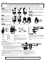
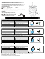
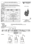
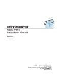
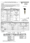
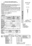
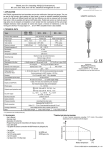
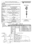
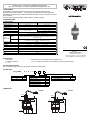
Thank you for choosing a NIVELCO instrument. We are sure that you will be satisfied throughout its use. 1. APPLICATION The EasyTREK is a liquid level transmitter, measuring by the non-contacting ultrasonic principle. The transmitter comes with scaleable 4 … 20 mA output, programmable relay and HART communication. This intelligent microprocessor based smart level transmitter is suited to measure most liquids under various process conditions. The device can be programmed using the supplied magnet or via HART if equipped. USER’S MANUAL 2. TECHNICAL DATA 2.1 GENERAL DATA Type SCA-36- SCA-38- 0.35 … 10m Measuring range (Xm − XM) 0.25 … 6 m Material PP Total beam angle 5° Ambient temperature -30 °C … +80 °C 0.3 … 3 bar (0.03 … 0.3 MPa) Pressure (absolute) 10.5 … 40 V DC, 3,6 W or 10.5 … 28 V AC / 4 VA Power supply / Consumption Outputs (programmable) -30 °C … +60 °C -30 °C … + 60 °C Process temperature 4-20 mA 600 Ω, galvanically isolated, (max. 250V), secondary lighting protection Error indication by the current output (programmable): 3.6mA; 22mA; hold last value SPST (NO) 48 V AC/ 5 A; AC12 For indication of echo loss (default) or for differential level control Current Relay Digital communication HART With Touch–Magnet Programming ±20 mm <2 m: 1 mm 2…5 m: 2 mm 5…10 m: 5 mm Accuracy of the setting Resolution 10 sec, 30 sec, 60 sec (programmable) Damping Electrical connection 6x0.5 mm2 shielded cable, ∅7.5 mm, length:3 m (can be ordered up to 30 m) Electrical protection Ingress protection Class III. IP 68 Weight ≈1.2 kg Manufacturer NIVELCO Process Control Co. H-1043 Budapest, Dugonics u. 11. Phone: (36-1) 369-7575 ♦ Fax: (36-1) 369-8585 E-mail: [email protected] http://www.nivelco.com 2.2 ACCESSORIES − − − User’s manual 1 x Magnetic screwdriver 1 x 1” nut – – Programming manual + CD ROM (for versions with HART only) 1 x 2” nut + sealing (for SCA-38 with 2” BSP process connection), material: EPDM 2.2.1 Optional Accessories SAA-110: Transparent pipe connector for LED status observation, SFA- 3: flange 2.3 ORDER CODE EasyTREK S C A — 3 Range 10 m 6m Code 6 8 — Mounting / Material 1" BSP or 1" and 2" BSP 1" BSP and 2" NPT 1" BSP fast connecting gland / PP Mounting bracket 200 mm Mounting bracket 500 mm Mounting bracket 750 mm Code 0 N F K L M Output 4 … 20 mA+relay 4 … 20 mA+HART+relay Code 2 4 2.4 DIMENSIONS SCA-380 SCA-360 21 1"BSP ~ø98 21 1"BSP 2" BSP 2" NPT ~60 B ~166 16 ~190 B BSP 15 NPT 22 16 ~ø98 3. INSTALLATION ATTENTION! Before mounting the unit in its final position, make sure that the programming points of the unit are accessible with the supplied magnet, the LEDs are clearly visible and the level of the liquid can be changed between its minimum and maximum during the programming session. If any of the above conditions are not met, the programming should be carried out before mounting the unit in its final position. (See 5. Programming) When mounted on a pipe, we recommend the use of the SAA-110 transparent pipe connector that enables on-site programming. Positioning: The optimal position of the EasyTREK is between r=(0.2 to 0.4)d of the tank. This will prevent unwanted interference caused by dome-top tanks. The sensor face has to be parallel with the surface of the liquid within ± 2°. r Wind: Intense movement of the air may effect the ultrasonic measurement and cause inaccuracy or eventually make it fail. Vapors, fumes: Vapors and fumes of gases may radically reduce the measuring range of the device (e.g.: chemicals, outdoor tanks under sunshine). Stand-off pipe: The structure of the stand off pipe should be rigid, the inner rim where the ultrasonic beam leaves the pipe should be rounded. d L 250 350 Obstacles: No object should protrude into the ultrasonic beam of the device (e.g.: ladder, thermometer, etc.). Foam: Foam on the surface of the liquid can make ultrasonic measurement difficult or eventually make it fail. Mount the device in a location where foam building is minimal or use a stilling D ≥ ø100 D ≥ ø100 pipe. Temperature: The transmitter should be protected against overheating (e.g. by direct sunshine) to avoid inaccurate measurement. L 150 200 250 Dmin. ∅ 60 ∅ 65 ∅ 75 Dmin. 4. ELECTRICAL INSTALLATION Brown Brown Green Yellow Pink Grey White Shielded T R A N S M I T T E R Cable Red LED "ECHO" Green LED Top view of the neck section Supply voltage Power Supply Green Grey Current Output White Yellow Pink Relay Output Shielding Junction box Denotation of the color wires: − Brown Power supply − Green Power supply − Yellow Relay output − Pink Relay output − Grey Current output − White GND − Shielding To be grounded Extending the cable: − When extending the cable, use a junction box. Shielding of the unit cable and that of the extension cable should be connected and grounded at the end of the extension cable. − Extend only wires required for the purpose of the application. In case of DC power supply the unit is polarityindependent. The relay is NO type Three-wire installation is possible in case of DC power supply by connecting the GND and the (-) pole of the power supply. In this case galvanic isolation is not provided. 5. PROGRAMMING 4 10 20 Iout F 0 100% E x After performing electrical installation according to 4 the unit is ready for operation. For ultimate temperature compensation accuracy, switch on the device 1 hour before programming. Programming can be performed in two ways: • On-site, using the liquid level as reflecting surface (only if the programming points are accessible on the unit, the LEDs are visible and the level of the liquid can be changed between the its minimum and maximum during the programming session). • Off-site, using a flat object as reflecting surface (e.g.: table or wall). 0% F ≥ xm E ≤xM The following features can be programmed using Touch-Magnet Programming with the supplied magnetic screwdriver: − Assignment of the 4 mA analogue output to a required min. level / max. distance (E) (factory default: XM max. measuring distance) − Assignment of the 20 mA analogue output to a required max. level / min. distance (F) (factory default: Xm min. measuring distance) − Error indication by the current output (factory default: hold last value) − Relay switching differential (if not programmed the relay is for echo loss indication) (factory default: echo loss indication, relay NO) – Damping (factory default: 60 sec) Note: Current output can also be assigned in inverted mode: 4 mA = 100 %, 20 mA = 0 % ATTENTION! When using off-site calibration, distance between the reflecting object and the unit must correspond to the required 4/20 mA values. [m A ] Touch-Magnet Programming is only possible if the EasyTREK receives valid echo i.e. “ECHO” LED is lit! Is the “ECHO” LED blinking the search for echo is in process. In case of EasyTREK with HART communication (SCA - 3 - 4) Touch-Magnet Programming is only possible if the transmitter is in the “LEV" measuring mode (factory default). Thus the relay switching difference between “ON” and “OFF” must be greater than 20 mm. Interpretation of LED statuses: = LED is on, = LED is blinking , = LED is off = LEDs are blinking alternatively The left-side LED symbol in the programming table below corresponds to the GREEN LED, while the right-side LED corresponds to the RED LED of the device. Programming: Open up the supplied screwdriver to access the magnet. When programming, put the magnetic part to one of the symbols: magnet Green LED Red LED screwdriver A or B according to the programming sequence described below and check the LEDs for their status. Make sure that after programming, the unit will not be exposed to a strong magnetic field! Minimum level, 0%, empty tank (assignment to 4 mA) Place the EasyTREK at a distance from the target corresponding to the required minimum level. Action LED indication 1) Check for valid echo = Valid echo received, transmitter programmable 2) Place magnet to the symbol “A” = EasyTREK in programming mode 3) Hold magnet in place = Distance assigned to 4 mA 4) Remove magnet when all LEDs are off = Programming completed E Use level in tank or a fix target e.g. the wall Maximum level, 100%, full tank (assignment to 20 mA) Place the EasyTREK at a distance from the target corresponding to the required minimum distance/maximum level. (Do not forget to check for valid Echo!) Action LED indication 1) Place magnet to the symbol “B” = EasyTREK in programming mode 2) Hold magnet in place = Distance assigned to 20 mA 3) Remove magnet when all LEDs are off F = Programming completed Use level in tank or a fix target e.g. the wall. Programming relay switch-on point (the level where the relay becomes energized) Place the EasyTREK at a distance from the target corresponding to the required switch-on point. (Do not forget to check for valid Echo!) Action LED indication 1) Place magnet to the symbol “A” = EasyTREK in programming mode 2) Place magnet to the symbol “B” = Programming in progress 3) Hold magnet to symbol “B” = Programming in progress 4) Place magnet to the symbol “A” = Programming of the switch-on point 5) Remove magnet when all LEDs are off = Programming completed Use level in tank or a fix target e.g. the wall. Programming relay switch-off point (the level where the relay becomes de-energized) Place the EasyTREK at a distance from the target corresponding to the required switch-off point. (Do not forget to check for valid Echo!) Action LED indication 1) Place magnet to the symbol “A” = EasyTREK in programming mode 2) Place magnet to the symbol “B” = Programming in progress 3) Hold magnet to symbol “B” = Programming in progress 4) Keep holding magnet to “B” = Programming of the switch-off point 5) Remove magnet when all LEDs are off = Programming completed Use level in tank or a fix target e.g. the wall. Note: To re-configure the relay for indication of ECHO LOSS, perform a RESET (see later) that will reset all parameters to default. Programming “Error indication” by the current output Place the EasyTREK against a target to obtain valid Echo required for programming! Action LED indication 1) Place magnet to the symbol “A” = EasyTREK in programming mode 2) Place magnet to the symbol “B” repeatedly to select the required error indication mode = Hold last value = 3,6 mA = 22 mA 3) Place magnet to the symbol “A”” = Programming completed Note: The current output will be – according to the selected error indication – 3.6 mA, 22 mA or the last measured value as long as the error continue to exist. “Damping” Place the EasyTREK against a target to obtain valid Echo required for programming! Action LED indication 1) Place magnet to symbol “B” = EasyTREK in programming mode 2) Place magnet to the symbol “A” repeatedly to select the required damping = 10 sec = 30 sec = 60 sec 3) Place magnet to symbol “B” = Programming completed Note: If your process allows it, leave the Damping at factory default (60 sec). Change it only if your process is fast and the output can not track the level. RESET: to factory default Place the EasyTREK against a target to obtain valid Echo required for programming! Action LED indication 1) Place magnet to the symbol “B” = EasyTREK in programming mode 2) Place magnet to the symbol “A” = Programming in progress 3) Hold magnet to the symbol “A” = Reset in progress 4) Remove magnet when all LEDs are off = Programming completed Indication of programming error (by the LEDs) Action LED status = error indicated Correction Attempted programming = blinking twice = No Echo Find valid echo Attempted programming = blinking three times = access denied (access code active) Access code can be activated through HART only Attempted programming = blinking four times = EasyTREK not in “LEV” meas. mode RESET the EasyTREK Programming of the relay = blinking alternately = switch-differential too small Set switch-differential greater than 20 mm 6. MAINTANCE, REPAIR The unit may require occasional maintenance of the sensor face by cleaning its surface, especially where sticky, adhering liquid may splash on it. A thin layer of dirt may not cause any trouble, however heavily fuming chemicals may reduce the efficiency of the sensor. Cleaning of the sensor face must be carried out in a way that does not harm polypropylene. Equipment sent back for repair should be cleaned or sterilized by the User. Repairs during or beyond guarantee period are carried out solely by the manufacturer. 7. STORAGE CONDITIONS Environmental temperature range: -35 ... +60 °C Relative humidity: max. 98 % 8. WARRANTY All Nivelco products are warranted free of defects in materials or workmanship for a period of two years from the date of purchase. Repairs under guarantee are carried out at the Manufacturer's premises. The Purchaser is liable for costs of dismantling and re-installation as well as transport costs. Nivelco shall not be liable for misapplication, labor claims, direct or consequential damage or expense arising from the installation or use of equipment. sca3802a0600h_03 October, 2001 Technical specification may be changed without notice.