1
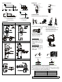
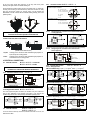
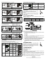
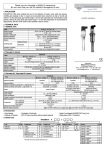
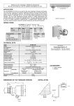
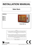
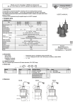
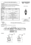
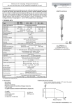
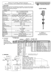
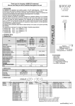
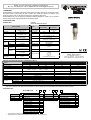
Thank you for choosing a NIVELCO instrument We are sure that you will be satisfied with it throughout its use 1. OPERATION The NIVOSWITCH is a mechanical resonance system excited, and kept in resonance by an electronic circuitry. The process medium, when reaching the tines of vibration fork, modifies the vibration. An electronic circuit senses this variation; which, on the elapse of the delay time, actuates the output circuit. The NIVOSWITCH can cover the majority of industrial level detecting applications. Overfill or dry run protection as well as pump control is made possible with the versatile level switch. 2. TECHNICAL DATA GENERAL DATA USER’S MANUAL 2-WIRE DC, NORMAL AND EX APPROVED VERSION 2-wire DC R 400 / R 400 Ex 40 bar,PP flange: 6 bar, for Derating see diagrams 0.69 … 3 m Maximum pressure Probe length Material of the wetted parts Medium temperature range Ambient temperature range Medium density DIN 1.4571, Halar (ECTFE) coated -40°C to +130°C, for Derating see Derating diagrams -40°C to +70°C, for Derating see Derating diagrams ≥ 0.7 kg/dm3 Liquids ≥ 0.05 kg/dm3 ≤ 10000 mm2/s (cSt) Solids* Liquid viscosity When immersed Response time Version When free 0.5 sec ≤1 sec at high density setting (ρ ≥ 0.5 kg/dm3) ≤ 2 sec at low density setting (ρ < 0.5 kg/dm3) Output mode indication R-4-6 R-4-8 Ex Electric connections (wire cross section) Mech. Protection Output Consumption Power supply (U) Setting operating mode Setting Sensitivity R-4-7 R-4-9 Ex Integral cable Connector (2 x 0.5 mm2) IP 65 IP 68 DC current change: When free: 9 ± 1 mA; When immersed: 14 ± 1 mA < 0,5 W 15 … 27 V DC Provided by the JDT 131 N-ExR remote switching unit for the Ex version By switch on the remote switching unit (low failsafe, hight fail-safe) Wire selectable Electrical protection Class III Ex protection mark EEx ia IIC T4 … T6 Intrinsically safe data Bicolour (LED) Output can be changed by test magnet Operation test U < 28,4 V, I < 100 mA P<1,4 W, Ceq < 7 nF Leq ≈0 For temperature classes see 5.1. Manufacturer: NIVELCO Process Control Co. H-1043 Budapest, Dugonics U. 11. Phone: (36-1) 369-7575 Fax: (36-1) 369-8585 E-mail: [email protected] http://www.nivelco.com 2-WIRE AC AND 3-WIRE DC VERSIONS, TO DRIVE RELAYS, PLC-S 2 wire AC Version R-4-1 Electric connections (wire cross section) Mechanical protection High/low mode setting 3 wire DC R-4-2 Connector Integral cable (4 x 0.75 mm2) IP 65 IP 68 Connection within connector Wire selectable Not available, fixed to: Solids: ρ ≥ 0.5 kg/dm3 * Liquids: ρ ≥ 0.7 kg/dm3 Density programming Output R-4-4 Connector IP 65 switch selectable Integral cable (5 x 0.5 mm2) IP 68 Wire selectable switch selectable Wire selectable Field selectable, galvanically isolated Field selectable, PNP/NPN transistor PNP/NPN transistor Reverse polarity, overcurrent and short circuit protection 12 … 55 V DC < 0,6 W < 4,5 V Class III Imax = 350 mA DC / Umax = 55 V DC – – < 100 µA 2-wire AC, for serial connection Output protection Supply voltage Consumption Voltage drop in switched-on state Electrical protection max. continuous Current load min. continuous max. impulse Residual current (in switched off state) R-4-3 — 20 … 255 V AC, 50/60 Hz Depending on load < 10.5 V Class I 350 mA AC 13 10 mA / 255 V, 25 mA / 24 V 1,5 A / 40 ms < 6 mA 2.1. ACCESSORIES User’s manual, Guarantee sheet, Magnetic screw driver RPS-101 (optional). Sealing ring (2 mm thick KLINGER OILIT). Sliding sleeve RPH-112 (optional). 2.2. ORDER CODES NIVOSWITCH Fork ECTFE coated Standard Highly polished * ** Code A C G R - 4 Connections Code Length Code 1” BSP thread M SHORTY (69 mm)* 00 1” NPT thread P Standard (125 mm) 01 DIN DN50PN40 st.st flange ** G 0.2 to 3 m 02…30 2” ANSI st.st. flange** B 50A JIS st.st flange** K DIN DN50 PN16 PP flange ** F 2” ANSI PP flange ** A 50A JIS PP flange ** J 1 ½” Triclamp (ISO2852) T 2” Triclamp (ISO2852) R DN40 Pipe coupling (DIN11851) D DN50 Pipe coupling (DIN11851) E The "SHORTY” models are not applicable for solids. Flanged versions as standard come with flanges screwed on the 1” process connection. Output Code 2-wire AC with connector 1 2-wire AC with cable 2 2-wire PNP / NPN with connector 3 2-wire PNP / NPN with cable 4 2-wire DC with connector 6 2-wire DC with cable 7 2-wire Ex with connector 8 2-wire Ex with cable 9 2.3. DERATING DIAGRAMS 2.5 MATERIALS TA[°C] Special PVC 70 55 45 35 IL350 mA IL100 mA IL≤ 1 mA 95 105 115 130 TM[°C] For all models (exept PP flanged) For 3-wire DC models EPDM 1.4571 Polyamid, glassfibrereinforced Polyamid, glassfibrereinforced 1.4571 1.4571 Klingerit 1.4571 1.4571 1.4571 Klingerit 1.4571 pT [bar] 6 5 1 0 -20 3. INSTALLATION 0 50 90 Prevent the device from any mechanical damage. TM[°C] For models with Polypropylene flange pT=process pressure TM =medium temperature For 2-wire AC and DC models TA =ambient temperature IL = load current 2.4 DIMENSIONS ø40 SW=41 R-4– ~110 ~110 R - 4 0 0 – ”SHORTY” ø40 BSP / NPT 1" SW=41 69 BSP / NPT 1" 3.1. INSTALLATION ON LIQUIDS 125...3000 ~110 Sliding Sleeve Always use the HIGH density mode (LOW sensitivity)! Version with flange s=41 15 ø40 s=55 RPH-112 0.2...3m 18 For positioning the fork-tines, use the marking on the hexagonal neck. MARK • Use a TEFLON (PTFE) tape to aid the positioning of the fork-tine • If the fork-tine position is irrelevant, use the sealing ring provided Low viscosity liquids On applications, where the forktines are easily freed from the process medium, any of the mountings shown to the right is possible. High viscosity liquids On applications, where the forktines are not freed easily from the process medium, only a vertical (top) mounting is recommended. Installation options BSP 1 1/2" Threaded version TRICLAMP (ISO 2852) Critical distances (xmin > 5 mm) Pipe Coupling R_D DN40 R_E DN50 RD 65x1/6 RD 78x1/6 For pipe mounting, fork-tines must be parallel to the direction of flow 3.2 INSTALLATION ON LIGHT, FREE FLOWING SOLIDS* Before mounting the unit, it is advised to program the density (only DC versions) on a small sample of the material to be detected. E.g.: Immerse the unit into a bucket of the material and check for reliable switching. Density Specific Gravity HIGH ( LOW Sensitivity) ρ ≥ 0,5 kg/dm3 LOW (HIGH Sensitivity) ρ < 0,5 kg/dm3 Use the fork with the HIGH Density setting if possible * The ”SHORTY” models are not applicable for solids The recommended mounting position on light, free flowing solids, is vertical (top) mounting. Side mounting is recommended only where the fork-tines are easily freed from the process medium (ex.: through gravity). For side mounting, the NIVOSWITCH must be mounted with the fork-tines standing vertically (look for the positioning marks). 4.2.1. Connector version R – 4 – 3 All models except the ”SHORTY” LED "M" - Operation mode H= High - level limit switch 3 L= Low - level limit switch 2 M "D" - Density 1 L H= High D L H H Do not set a lower density than necessary, as this may result in the probe detecting even slight residues of material adhering to it. L= Low The “SHORTY” models LED "M" - Operation mode H= High - level limit switch 3 L= Low - level limit switch 2 M 1 H L 4.2.1.1. Protect the probe from downfalling material! Fork-tines should not be exposed to mechanical load. Wiring diagram for 3 wire DC version with connector in case of relay application 3.3. SWITCHING POINT, SWITCH DIFFERENTIAL PNP-wiring NPN-wiring Terminal block cover can be rotated in 90° steps to ensure appropriate cable positioning 4.2.1.2. (Values are for water at 25°C) Liquids: Solids: Wiring diagram for 3-wire DC version with connector for PLC application switching point as well as the switch differential slightly depends on liquid density and mounting position switching point as well as the switch differential slightly depends on material features and mounting position + 24V DC IN COM 4. ELECTRICAL CONNECTIONS PNP-wiring R – 4 – 1 connector R – 4 – 2 cable 4.1. 2 WIRE AC VERSIONS PLC (A-B sink input, OMRON SYSMAC,...) 4.2.2. Integral cable version R–4–4 4.2.2.1. Relay application PNP mode HIGH density (Liquids: ρ ≥ 0.7 kg/dm3; Solids*: ρ ≥ 0.5 kg/dm3) DO NOT POWER UP THE DEVICE WITHOUT A LOAD CONNECTED IN SERIES WITH THE UNIT AND WITHOUT GROUNDING IT 4.1.1. Connector version R – 4 – 1 L1 3 R 2 3 N R 2 1 N LOW-level limit switch 1 PNP mode LOW density (Solids*: ρ < 0.5 kg/dm3) L1 LOW-level limit switch black 4.1.2. Integral cable version R – 4 – 2 grey brown blue black N L 1 green/yellow Junction box LOW-level limit switch 4.2. 3 WIRE DC VERSIONS L R blue R black + grey Junction box Junction box LOW-level limit switch HIGH-level limit switch NPN mode HIGH density (Liquids: ρ ≥ 0.7 kg/dm3; Solids*: ρ ≥ 0.5 kg/dm3) 1 N black + brown green/yellow R black HIGH-level limit switch In case of overload caused by short circuit, transistor will switch on and off, and LED will start to blink. R black - blue Junction box - brown white white R–4–3 R–4–4 R blue - blue Two of the signal wires (black and brown) are insulated. Only one of these two wires is used, dependent on the operating mode (High or Low). Remove the insulation only from the wire, corresponding to the desired operating mode. - brown white white Terminal block cover can be rotated in 90° steps to ensure appropriate cable positioning R + brown HIGH-level limit switch brown HIGH-level limit switch grey Junction box LOW-level limit switch * The ”SHORTY” models are not applicable for solids + blue grey Junction box HIGH-level limit switch Operating diagram of the 2-wire DC version NPN mode LOW density (Solids*: ρ < 0.5 kg/dm3) + brown - brown white + blue grey grey Junction box Junction box LOW-level limit switch HIGH-level limit switch 4.2.2.2. PLC applications (A-B sink input, OMRON SYSMAC…) PNP mode HIGH density (Liquids: ρ ≥ 0.7 kg/dm3; Solids*: ρ ≥ 0.5 kg/dm3) brown black IN white black PLC blue IN blue grey grey COM Junction box PLC COM Junction box LOW-level limit switch HIGH-level limit switch black IN grey white black PLC blue RED 14 ± 1 mA Free GREEN 9 ±1 mA Correct operation of the switching circuit of an installed device can be tested with the optional test magnet (RPS-101). Moving the test magnet in front of the marking on the cover of the housing the device must perform a switching (LED changes colour). Applying Ex approved models take into consideration the table of allowed temperatures listed below + 24VDC - brown + 24VDC - white Immersed 5.1. APPLYING EX APPROVED MODELS PNP mode LOW density (Solids*: ρ < 0.5 kg/dm3) brown Output OPERATION TEST + 24VDC - brown + 24VDC - white LED black - blue Fork R white R black Temperature classification PLC blue grey COM Junction box Junction box LOW-level limit switch T5 60 °C 95 °C Ex STANDARD OR EX R–4–6 R – 4 – 8 Ex Ex L max=1m Q min=4mm2 Remote switching unit JDT 131-Ex 2 Integral cable version NIVOSWITCH 2 + 1 - LOW density (ρ < 0,5 4.3.2. Integral cable version kg/dm3) Potential balancing cable R<1 ohm HIGH sensitivity blue + + • brown blue - HIGH density(ρ ≥ 0,5 kg/dm3) LOW sensitivity LOW density (ρ < 0,5 kg/dm3) HIGH sensitivity Check connecting of the wires and position of the switches (if there are any). After connection and power up the tuning fork is operational. Operating diagram of the NIVOSWITCH (except 2-wire DC versions) FAILS HIGH-level limit switch RED LOW-level limit switch GREEN HIGH-level limit switch GREEN Free LOW-level limit switch RED Free or immersed HIGH or LOW NOT LIT *The ”SHORTY” models are not applicable for solids Output Imin OF F LED IN ON Immersed Operating mode IN Imin OFF ON Fork • • • 5. ADJUSTMENT Power supply CONDITIONS OF SAFE OPERATION • R–4–7 R – 4 – 9 Ex brown US 24 V, DC ± 10% Connector version NIVOSWITCH + 1 HIGH density (ρ≥0,5 kg/dm3) LOW sensitivity T4 60 °C 130 °C Table of possible temperatures HIGH-level limit switch 4.3. 2 wire DC versions 4.3.1. Connector version T6 60 °C 80 °C TAmbient TMedium Utáp Utáp Utáp Utáp Utáp The vibration fork level switch has to be supplied by a certified intrinsically safe circuit with maximum parameters only: Uo = 26.5 V Io = 100 mA Po = 1.4 W For installation of version R-4-9 Ex with integrated cable, there has to be a suitable connection box near the level switch. It is allowed for the vibration fork to get in contact with the liquid only; the installation has to guarantee that the housing (head) is outside the liquid. The level switch has to be connected to the local equipotential bonding. To avoid electrostatic ignition danger, the coated version type RA-4- Ex is allowed for substances with explosion group IIA or IIB only. 6. MAINTENANCE, REPAIR The NIVOSWITCH R-400 does not require routine maintenance. In some instances, however, the sensor probe may need occasional cleaning to remove surface deposits. This must be carried out gently, without harming the vibrating section of the vibrating fork. 7. STORAGE CONDITIONS Ambient temperature: -35 to +60°C Relative humidity: max. 98 % 8. WARRANTY All Nivelco products are warranted free of defects in materials or workmanship for a period of two years from the date of purchase. Repairs under guarantee are carried out at the Manufacturer's premises. The Purchaser is liable for costs of dismantling and re-installation as well as transport costs. Nivelco shall not be liable for misapplication, labour claims, direct or consequential damage or expense arising from the installation or use of equipment. rc4004a0600h_03 September, 2001 Nivelco reserves the right to change technical specifications without notice.