1
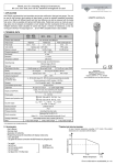
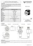
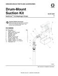
Thank you for choosing a NIVELCO instrument.
We are sure that you will be satisfied throughout its use.
Series R-300
Vibrating fork level switches
1. APPLICATION
NIVOSWITCH R-300 series vibrating forks are for level detection of powder, lumpy solids and granules.
Overfilling and emptying of silos or vessels can be prevented when using them as high or low fail safe
switches. The RC series (basic type insertion lenght = 125 mm) with casted forks are recommended for small
granules, while the RL series (basic type insertion lenght = 137 mm) with welded forks are recommended for
larger granules. Both RC and RL series are also available in dust Ex versions.
USER’S MANUAL
2. TECHNICAL DATA
2.1 GENERAL DATA
TYPE
Medium pressure
Insertion length
Material of wetted parts
Medium temperature
Ambient temperature
Medium
Getting immersed
Switching delay
Getting free
Indication of operation
Test of operation
R–3–
40 bar, 6 bar with PP flange See Derating diagram
0.125 … 3 m
Casted fork DIN 1.4404, welded fork DIN 1.4571
-40 °C … +130 °C, See Derating diagram
-40 °C … +70 °C, See Derating diagram
ρ ≥ 0.01 kg/dm3
0.5 sec
≤ 1 s – selected high density (H) (ρ ≥ 0.5 kg/dm3)
≤ 3 s – selected high density (L) (ρ < 0.5 kg/dm3)
Bi-colour LED
Output state can be changed with test magnet
2.2 TWO-WIRE DC VERSION
TYPE
R–3–6
2-WIRE DC
R–3–7
Connector
3 m cable (2 x 0.5 mm2)
IP 65
IP 68
DC current change: fork free: 9 ± 1 mA; fork immersed: 14 ± 1 mA
< 0.5 W
15 … 27 V DC
LOW fail safe L or HIGH fail safe H on suggested isolator, by switch
By inverting the polarity of connection
Class III
Electric connection
Ingress protection
Output
Power consumption
Supply voltage
Selection of operation
Selection of sensitivity
Electric protection
Manufacturer:
NIVELCO Process Control Co.
1043 Budapest, Dugonics u. 11.
Phone: (36-1) 889 - 0100 ♦ Fax: (36-1) 889 - 0200
e-mail: [email protected] ♦ www.nivelco.com
2.3 TWO-WIRE AC, THREE-WIRE DC VERSION
2-WIRE AC
R-3-1
R-3-2
TYPE
Electric connection
R-3-3
3 m cable, 4 x 0.75 mm2
max. cable length. 30 m
IP 65
IP 68
By altering the connection
Not possible ρ ≥0.5 kg/dm3
3 m cable 5 x 0.5 mm2
max. cable length 30 m
IP 65
IP 68
By switch on the cover
By inverting the polarity of connection
By switch on the cover
With wiring
By changing polarity NPNGalvanically isolated
serial AC output
and PNP transistor switch
PNP/NPN transistor switch
—
changing polarity, oversurge, short cut
20 … 255 V AC, 50/60 Hz
12 … 55 V DC
Depending on load
< 0.6 W
< 10.5 V
0…1.8 V
Class I
Class III
350 mA AC 13, for Ex version (C, D) 140 mA
Imax = 350 mA for Ex version 200 mA DC / Umax = 55 V DC
10 mA / 255 V. 25 mA / 24 V
–
1.5 A / 40 ms
–
< 6 mA
< 10 µA
xII ½ D IP 65 T 160°C for C, E output codes, xII ½ D IP 68 T 160°C for D, F output codes
connector
connector
Ingress protection
Selection of operation (Low fail safe - L, High fail safe - H)
Selection of density. (low density– L, high density – H)
Output
Output protection
Supply voltage
Power consumption
Voltage drop between terminal points during operation
Electric protection
max. continuous
Current load
min. continuous
max. impulse
Residual current after switch off
Mark of explosion protection
3-WIRE DC
R-3-4
2.4 ACCESSORIES
– User’s Manual
– Certificate of Warranty
– Declaration of Conformity
– RPS-101 type screw driver with test magnet (optional)
– Gasket 2 mm klingerit (KLINGER OILIT) ring (1 pc)
– Sliding sleeve: RPH-112 (optional)
2.5 ORDER CODE
NIVOSWITCH
TYPE
Casted fork
Welded fork
CODE
C
L
CONNECTION
1” BSP
1½” BSP
1” NPT
1½” NPT
DN50 PN 16 PP DIN
DN50 PN 40 1.4571 DIN
2” ANSI RF150 PP
CODE
M
H
P
N
F
G
A
R
CONNECTION
2” ANSI RF 600 1.4571
JIS 10K 50 A PP
JIS 40K 50 A 1.4571
1½” Triclamp
2” Triclamp
Pipe coupling DN 40
Pipe coupling DN 50
* The order code of an Ex version should end is ‘Ex’
- 3
CODE
B
J
K
T
R
D
E
-
*
INSERTION LENGTH
CODE
OUTPUT
125 / 137 mm
200 / 175 mm
0.3 … 3 m
01
02
03…30
2-wire AC+ connector
2-wire AC + cable
3-wire DC + connector
3-wire DC + cable
2-wire DC+ connector
2-wire DC + cable
Dust Ex
2-wire AC+ connector
2-wire AC + cable
4-wire DC+ connector
2-wire DC + cable
CODE
1
2
3
4
6
7
C
D
E
F
2.6 DERATING DIAGRAMS
Pipe coupling DIN11581
~117
~108
Triclamp (ISO 2852)
Ø 40
Ø 40
Tank pressure (pT) versus the ambient temperature (TM)
Ø 28
~130
~125
1½", 2" Triclamp
(ISO 2852)
A
Temperature limits for DC devices [IL] Current load
[TA] ambient temperature
TYPE
Conn.
A
RCD
DN 40
RD 65x1/6
RCE
DN 50
RD 78x1/6
2.8 MATERIALS
Tank pressure (pT) versus ambient temperature (TM)
for PP flange
With integral cable
With connector
PVC
EPDM
KO35 (1.4571)
Polyamid,
glassfibre reinforced
KO35 (1.4571)
Temperature limits AC [TA] ambient temperature [TM] medium temperature
Klingerit
(1.4571)
2.7 DIMENSIONS
KO35 (1.4571)
Klingerit
(1.4571)
RLH–301–, RLH–302–
113
RLH–303..30–
Polyamid,
glassfibre reinforced
40
3. MOUNTING
113
BSP1 1/2"
or
NPT 1 1/2"
Prevent device from being damaged during delivery, storage, mounting and test.
40
300-3000
S=55
BSP1 1/2"
or
NPT1 1/2"
137/175
S=55
Adjustable with
sliding sleeve
Flange
s = 41
Ø40
15
~110
Ø 40
~113
~110
RC–3–
13
Ø 40
s = 55
RPH - 112
s = 41
Before installation it is advised to try the operation of the level switch in a small
sample of material in order to set the proper density. Tightening of the model with
thread process connection should only be done with open end SW = 41
Marking
0,2 ... 3 m
0,2 ... 3 m
125 ... 3000
18
1" BSP
For positioning of the fork tine use the marking on the hexagonal neck.
The recommended mounting position of the fork for light, free flowing solids, is
vertical (top) mounting. Side mounting is recommended only in cases when the
fork-tines are easily freed from the process medium. In case of side mounting,
NIVOSWITCH must be mounted with the fork-tines standing vertically.
When determining mounting location, take into account the possible caving or
arching of the material in the tank.
The fork should be protected against falling materials. This is to be done so that
material could not clog between the fork and the protection plate.
R–3–3
R–3–4
4.2. THREE-WIRE DC VERSION
In case of overload caused by short circuit, the transistor will switch on and off,
and the LED will start to blink.
4.2.1. Connector version R – 3 – 3
(LED)
indication
3
"M" - Operation switch
H =High level safe
2
M
H = High density
1
H
L = Low level safe
L
4.2.1.1.
"D" - Density switch
D
L
H
Wiring diagram of the three-wire DC connector version with relay
PNP wiring
4. WIRING
NPN wiring
Terminal block cover can be rotated in 90° steps to ensure appropriate cable
positioning.
R – 3 – 1 with connector
R – 3 – 2 with cable
4.1. TWO-WIRE AC
L = Low density
4.2.1.2.
Wiring diagram of the three-wire DC connector version with PLC
THE UNIT SHOULD NOT BE POWERED UP WITHOUT
GROUNDING AND EXTERNAL LOAD!
+
24V DC
IN
PLC
COM
4.1.1. Model with connector R – 3 – 1
PNP wiring
L1
3
R
2
N
3
R–3–4
4.2.2. Integral cable version
R
2
1
4.2.2.1. Wiring with relay
N
PNP wiring high (H) density (ρ ≥ 0.5 kg/dm3),
1
L1
+
brown
Wiring of Low fail safe mode (L)
brown
Wiring of High fail safe mode (H)
R
black
black
-
blue
Terminal block cover can be rotated in 90° steps to ensure appropriate cable
positioning.
-
white
white
R
blue
grey
grey
Junction
box
+
Junction
box
4.1.2. Integral cable version R – 3 – 2
Two of the signal wires (black and brown) are insulated. Only one of these two
wires is used, depending on the operating mode (High or Low). Remove the
insulation only from the wire corresponding to the desired operating mode.
brown
brown
R
blue
black
N
L1
green/yellow
Junction
box
Wiring of Low fail safe mode (L)
R
blue
black
L1
N
Wiring for L (Low fail safe
operation)
PNP output low (L) density, (ρ < 0.5 kg/dm3)
+
brown
white
R
black
grey
Junction
box
Wiring of High fail safe mode (H)
brown
-
white
black
-
blue
green/yellow
Wiring for H (High fail safe op.)
Junction
box
Wiring of Low fail safe mode (L)
R
blue
+
grey
Junction
box
Wiring of High fail safe mode (H)
5. SET UP, ADJUSTMENT, PUTTING INTO OPERATION
-
white
white
R
black
R
black
+
blue
-
blue
grey
grey
Junction
box
Junction
box
Power
supply
Fork
Operation
Indicati
on
(LED)
H
RED
L
GREEN
H
GREEN
L
RED
H
or
L
NONE
Wiring for H (High fail safe op)
Output
Immersed
white
white
R
+
Junction
box
Junction
box
Wiring for L (Low fail safe operation)
Free
Wiring for H (High fail safe op)
4.2.2.2. Wiring with PLC
Free
or
immersed
NONE
State of operation of the 2-wire DC version
4.2.2.3. PNP wiring high (H) density, (ρ ≥ 0.5 kg/dm3)
Villa
brown
black
IN
blue
grey
white
black
PLC
IN
blue
grey
COM
Junction
box
PLC
Output
Immersed
RED
14 ± 1 mA
Free
GREEN
9 ±1 mA
COM
Junction
box
Wiring for L (Low fail safe operation)
Indication (LED)
+
24VDC
-
brown
+
24VDC
-
white
UTÁP
grey
UTÁP
blue
-
grey
Imin
blue
R
black
OFF
black
YES
UTÁP
-
brown
In
+
brown
ON
NPN wiring low (L) density, (ρ < 0.5 kg/dm3)
UTÁP
In
Wiring for L (Low fail safe operation)
Check wiring and setting of switches (if any). After powering up the vibrating fork
is operational.
The operation is summarised in the table below.
UTÁP
brown
Imin
+
brown
OFF
NPN wiring high (H) density, (ρ ≥ 0.5 kg/dm3)
Wiring for H (High fail safe op)
OPERATION TEST
Operation of the switch can be verified with the help of the
optional screwdriver with magnet (Type RPS-101).
When moving the magnet in front of the marking on the
enclosure the state of the switch (colour of the LED) should
be changed.
PNP wiring low (L) density, (for solids: ρ < 0.5 kg/dm3),
brown
black
IN
blue
grey
+
24VDC
-
brown
+
24VDC
-
white
white
black
PLC
PLC
blue
grey
COM
Junction
box
6. MAINTENANCE, REPAIR
Junction
box
Wiring for L (Low fail safe operation)
Wiring for H (High fail safe op)
4.3. TWO-WIRE DC VERSION
4.3.1. Connector version
2
1
+
Recommended
switching unit
UNICONT
PKK-312-
-
H density, (ρ ≥ 0.5 kg/dm3)
4.3.2. Integral cable version
brown
Recommended
R–3–6
2
1
-
blue
-
H density, (ρ ≥ 0.5 kg/dm3)
Recommended
switching unit
UNICONT
PKK-312- L density, (ρ < 0.5 kg/dm3)
R–3–7
blue
+ switching unit
UNICONT
PKK-312-
+
The instrument does not require regular maintenance. In some
instances, however, the probe may need occasional cleaning to
remove surface deposits. This must be carried out gently,
without harming the probe.
Repairs during or beyond the warranty period are carried out
solely by the manufacturer. Equipment sent back for repair
should be cleaned or sterilised by the User. The User must
declare that the above has been carried out.
7. STORAGE CONDITIONS
Ambient temperature: -25 to +60 °C
Relative humidity: max. 98%
8. WARRANTY
All NIVELCO products are warranted free of defects in materials or workmanship
for a period of two years from the date of purchase, as indicated in the Certificate
of Warranty.
Recommended
+ switching unit
brown
-
UNICONT
PKK-312-
L density, (ρ < 0.5 kg/dm3)
rcm3014a0600h_07
Sept, 2006
Nivelco reserves the right to change technical specifications without notice.