1
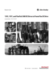
Chapter 2 - Specifications
External Output Signal (DOUT, Alarm Output, Lamp Output Port)
Rated Load Voltage
Maximum Load Current
Maximum Voltage Drop between Terminals
Isolation Method
(Interface Circuit)
DC12V to DC24V
100mA/point
1.5V (at 100mA load current)
Via photocoupler
(Connection Example)
+5V
DOUT(+)pin 8
Alarm Output(+)pin 10
Lamp Output(+)pin 22
R
Load
*1
Cable
SSTA06
PC357
DC24V
DOUT(-)pin 7
Alarm
Output(-)pin
9
4.7kΩ
Lamp Output(-)pin 21
D-sub 25 pin Connector
•
Be sure to operate the unit within its maximum load current. If the
maximum load current exceeds this range, a malfunction or PL damage may occur.
• Design your electrical system by adding the load current and voltage
values to the terminal voltage. If load current value used is large, a
maximum voltage of 1.5V will exist between the terminals.
• When connecting an induction load, be sure to connect the above
drawing's protection diode(*1).
2-10
PL-B920 Series User Manual