1
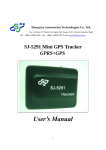
Sheng Jay Automation Technologies Co., Ltd. No. 12, Wulin St., Shulin City, Taipei 238, Taiwan, R.O.C. (Shulin Industrial Park) Tel: +886-2-2684-1569 Fax: +886-2-2684-1567 E-mail: [email protected] SJ-5291 Automatic Vehicle Locator GPRS+GPS User’s Manual 1 Version History Date Version 2009-3-10 1.0 2009-4-29 2.0 Description of change Author Thomas New Server Software 1 Thomas Content 1. Introductions ....................................................................................................................................................................... 3 1.0 Overvie ...................................................................................................................................................................... 3 1.1 Features .................................................................................................................................................................... 3 1.2 Applications .............................................................................................................................................................. 3 1.3 Optional Software .................................................................................................................................................... 3 1.4 General Specifications ............................................................................................................................................. 4 1.5 GSM/GPRS Specification ........................................................................................................................................ 5 1.6 GPS Specification ................................................................................................................................................... 5 1.7 Antenna Connect...................................................................................................................................................... 6 1.7.1 GSM/GPRS Antenna Connect ..................................................................................................................... 6 1.7.2 GPS Antenna Connect .................................................................................................................................... 6 1.8 LED Indicator ...................................................................................................................................................... 6 1.8.1 Main Power Indicator ..................................................................................................................................... 6 1.8.2 Backup Battery Charger Indicator ............................................................................................................... 6 1.8.3 GPS Status Indicator ...................................................................................................................................... 6 1.8.4 GSM/GPRS Status Indicator ........................................................................................................................... 6 1.9 External Connection ............................................................................................................................................. 7 1.10 Mechanical specifications ....................................................................................................................................... 8 2. 3. 1.11 Environment specification ...................................................................................................................................... 8 1.12 Package List ............................................................................................................................................................. 8 Hardward Installation ...................................................................................................................................................... 9 2.1 Panel Introduction ................................................................................................................................................ 9 2.2 Panel Introduction ................................................................................................................................................ 9 2.3 SIM Card Installation ............................................................................................................................................. 9 2.4 GSM Antenna Installation.................................................................................................................................... 10 2.5 GPS Antenna Installation ................................................................................................................................... 10 2.6 Power Supply Installation .................................................................................................................................... 11 2.7 LED Status Indication ........................................................................................................................................ 11 2.8 Check AVL by SMS ............................................................................................................................................... 12 2.9 AVL Setting ............................................................................................................................................................ 12 Server setup and Software Installation ......................................................................................................................... 14 3.1 Overview ................................................................................................................................................................ 14 3.2 Requirements ......................................................................................................................................................... 14 3.3 Software Setup....................................................................................................................................................... 15 Q&A ................................................................................................................................................................................ 20 2 1. Introductions 1.0. Overview SJ-5291 is a versatile and economical platform for mobile positioning applications. It integrates SJA GPS module with Quad-band 850/900/1800/1900GSM/GPRS communication module and powerful microcontroller all onto a single board. It is enclosed in a solid casing for easy installation. SJ-5291 provides reliable Real Time vehicle GPS positions anytime anywhere in the world, providing the correct position and status of vehicles from remote locations onto computer displayed maps. Benefits such as increased fleet efficiency, improved public and driver safety, better emergency response time, enhanced fleet control, and good public relations are all realized through the proper implementation of SJ-5291 system. The SJ-5291 transmit NMEA message to 24-hrs Control Center by Packet-Switch for monitoring through either GPRS or SMS massage system. Control center sets command by sending commands for monitoring through GSM system or Internet access. 1.1. Features ◆ Supports Quad band 850/900/1800/1900 MHZ operation ◆ GPRS multi-slot class 10 and mobile station class B ◆ Integrated TCP/IP stacks ◆ SMS transfer via GSM/GPRS ◆ Remote control via SMS ◆ Real-time GPS tracking ◆ Real-time vehicle status monitoring ◆ Dual data communication capability through GPRS and SMS ◆ Supports speaker and microphone interface ◆ 6 Bi-directional digital IO ports with voltage protected up to 40V ◆ RS232 interface with USB connector for Setup ◆ Power supply and ◆ 4 LED indicators for power, battery charger in progress, GSM/GPRS and GPS status ◆ Built-in 1700mAh Recharge battery 1.2 low battery detection acknowledge Applications ◆ Security (cash carrier vehicle and police vehicle) ◆ Commercial vehicle monitor and driver performance monitor ◆ Rental car monitoring and theft recovery ◆ Emergency (ambulance and fire engine) ◆ Hazardous waste management 1.3 Optional Software ◆ Data logger in PC ◆ Up to 4 SMS numbers for emergency report ◆ Self geofence and out of range alert 3 1.4 ◆ Speed detection ◆ GPS reporting internal user programmable ◆ System status report(IO, power, battery) ◆ Security administration General Specifications Parameter Specification Power Supply 9~60 VDC Power Consumption Power down 17 Sleep mode 45 mA GPRS class 10(Ave) mA 130 mA Firmware Upgrade USB Function Setting USB SIM card type 1.8V, 3V LED Status Indicator Main Power/ Battery charge in progress/GPRS/GPS Serial port interface USB Digital GPIO 6 Bi-directional digital IO ports with voltage protected up to 40V 4 1.5 GPRS/GSM Specifications Parameter Specification Frequency Quad band 850MHz/900MHz/1800MHz/1900MHz Class 4(2W) for EGSM 850 and 900 Output Power Class 1(1W) for GSM 1800 and 1900 1.6 Protocol support TCP GPRS Multi-slot Class 10 GPRS Mobil station Class B Coding scheme CS1,CS2,CS3,CS4 PBCCH support Yes USSD support Yes Downlink/ Uplink max. 85.6Kbps/42.8 kbps GPS Specifications Parameter Specification Transmission data NMEA 0183 Ver3.01 Receiver channels / Fixing method SirRF III Acquisition sensitivity -137 dBm Tracking sensitivity -158 dBm Receiver frequency 1575.42MHz L1 C/A Code 20 channels Accuracy (1)Position 5m CEP (2)Datum WGS-84 Time To First Fix 45Sec(typ) (1)Cold start 35Sec(typ) (2)Warm start 1Sec(typ) (3)Hot start Dynamic condition 4G (39.2m/sec2) Interface UART Operational Limits (1) Altitude < 18,000m (2) velocity < 500m/s Bit rate 9600 bps Start bit 1 bit Stop bit 1 bit Data bit 8 bit 5 Parity None Output sentences GPGGA/GPGSA/GPGSV/GPRMC Refresh time 1Sec 1.7 Antenna Interface 1.7.1 GPRS/GSM Antenna Connector SJ-5291 offers a SMA type connector which must be connected to an external passive antenna. 1.7.2 GPS Antenna Connector SJ-5291 offers a SMA type connector which must be connected to an external active antenna. The connector receives RF signal input and antenna power supply. 1.8 LED Indicator 1.8.1 Main Power Indicator For the Main Power Indicator through red LED, detailed information is shown in the following table. 1.8.2 LED mode Operation status On Main power on Off Main power off Backup Battery Charger Indicator For the Main Power Indicator through yellow LED, detailed information is shown in the following table. 1.8.3 LED mode Operation status On Backup battery charge in progress Off Backup battery charge complete GPS Status Indicator For the GPS status indicator through green LED, detailed information is shown in the following table. 1.8.4 LED mode Operation status On Searching satellite 1 sec On /1 sec Off Tracking satellite GSM/GPRS Status Indicator For the GPRS/GSM status indicator through green LED, detailed the information is shown in the following table. LED mode Operation status On GSM/GPRS is not running 3000 ms On/3000 ms Off Flashing Indicates GPRS data transfer: 6 1 sec On /1 sec Off Flashing 1.9 GPRS does not find the network / GSM running External Connection Pin Signal Type Description 1 Digital_ I/O2 I/O Bi-directional I/O 2 Digital_ I/O1 I/O Bi-directional I/O 3 GND GND GND 4 Vcc Vcc Connection to car ACC (9~40 VDC) 5 Digital_ I/O 3 I/O Bi-directional I/O 6 Digital_ I/O 4 I/O Bi-directional I/O 7 Digital_ I/O 5 I/O Bi-directional I/O 8 Digital_ I/O 6 I/O Bi-directional I/O Front view of External Connect 7 1.10 Mechanical specification 1.11 Parameter Specification Dimension 100 mm(L) 85 mm(W) X 28 mm(H) Weight 100g Environment specification Parameter Specification Operating - 20°C to +60°C Storage -40°C to +80°C Temperature 1.12 Package List Before getting started, please make sure you have the following devices, programs and accessories. 1. SJ-5291 device x 1 2. GPS antenna x 1 3. GSM/GPRS antenna x 1 4. CD-ROM which contains server program and related documents x 1 5. Cable x 1 6. Mini USB cable x 1(optional) 8 2. Hardware Installation 2.1. Precaution 1) Check if all parts are included as the Package List. 2) Prepare a SIM card and use a mobile phone to unblock the SIM PIN code. Be sure that if use the SIM card can dial out or receive calls without problem. 2.2. Panel Introduction 2.2.1. Front Panel 2.2.2. Rear Panel 2.3 SIM Card Installation Insert the SIM card by sliding it into the card holder slot, as shown in the figure. PS. If you want to replace the SIM card, press the push button and pull out the holder. 9 2.4 GSM Antenna Installation Connect and fasten the GSM antenna to the unit, as shown in the figure. 2.5 GPS Antenna Installation The GPS antenna is used to receive the satellite signal in the sky. It should be placed on where it will have a unobstructed view of the sky, such as the windshield. 10 2.6 Power Supply Installation Simply connect the power cord to the power cord connector on the front side of the device. There is a power switch on the front side of the device, and you can turn it on/off by this switch. 2.7 LED Status Indication 1) After connected the power cord connector and turn the power switch on, the Power and Battery LED will light up. 2) The Bule LED of GPS will flash while being active. 3) The Green LED of GSM/GPRS will flash when sending or receiving messages. 4) Being during charging status, the Orange LED will light up. 11 2.8 Check AVL by SMS 1) After the Hardware Installation is done. You can send the” $IQUPOS,000000 “ by SMS to the installed device, and the position information included the latitude and longitude data will be response to you by the received AVL device. 2.9 AVL Setting Requirements Please using AVL with power supply amd connect with PC with Windows XP interface by Mini USB Cable. 1. Install Driver and Run set up program 2. Enter Password(Original setting is 000000)and press Connect Button. The program will search port automaticly When connet successly, wait for the number of AVL device ID 12 3. Press Read All Button will read through all AVL parameters 4. Press Read Button, can read the single setting value 5 Adjust the parameter, press Set Button to finish setting 6. Also can adjst all parameter, then press Set All Button to finish setting 7. If you forget AVL passowrd , you can press “Reset Default” Button. About parameter 1. Device ID : set up AVL program ID, it must be letters and cipher, special charaters ( $@^#&*! etc.) is not accepted 2. Password : set up password of AVL program with cipher 3. Phone: set up AVL to sending SMS number, four setting is avalaible 4. Band : Select GSM System, (900 /1800 Mhz or 850 /1900Mhz) 5. GPRS : set up GPRS function starting 6. Server IP: set up server IP and Port 7. APN String: set up GPRS APN String、UserName、Password, please contact SIM provider 8. Time Interval: set up span time when GPS information transfer via GPRS to Server, range between 10~999 seconds 9. IO : six IO is avaible to used, When using Input ,it can detect outside signal When using Output, can be controlled via GPRS and SMS to export signal 13 3. Server setup and Software Installation 3.1 Overview The AVL contains the GSM/GPRS module and will send the location information to the Server. The Server should be installed on a stand-alone computer as a middle ware to control and manage several AVLs. Meanwhile, the client Viewer can be installed on other computers as a supervisor over the client/server architecture. 3.2 Requirements 1) Make sure the SIM card has been installed into the AVL, and the GPRS function is not blocked. 2) Fix IP Address is required. The AVL will send the GPS data and necessary information to the 3) Server by GPRS. PS: Test Server IP is 60.250.90.244 and port is 2500, it can connect to Test Server for your testing. 4) The PC system requirements as the following: Operating system: Windows XP. Or Vista .Net Framework 3.5 CPU: Intel P4 2.0 above. Hard disc: 2.0GB above. Memory: 2GB above. Ether Port (LAN Port): 10/100MBPS above. Fix IP 5) Please ensure SIM Card‟s PIN Code is disable. 6) Ensure GPRS service is available as well as APN, APN Name, APN Password. 14 3.3 Software and Drive Setup 1. Run Server.exe. Program 2. Click Setting Tab and Setting Server IP、Port、Language etc…. and Press “Save” Button 15 3. Press „Start” Button, will Run Timer and Data Recevier 4. Press Start Sever button to start Server, A Button: increase AVL ID, D Button delete AVL ID 16 5. When AVL transfers GPS back to Server, it is clear that AVLID pattern in list becomes green from grey 6. Click “Show Map “ Tab and select ID from the list , pattern change to Green which can be click “google Map” and use Google Map track AVL location 7.Use historical logger function, Click Track Recorded Tab 17 18 8. Select date, ID, starting and finishing time, Map Zoom, Timer, then press Show Path to show recorded path. 9. Other Function: (1) Report: I/O Alarm、SOS、Low Battery Status (2) Show Map on Google Earth (3) Simulate GPS Receiver: Show Map on Other Navigate Software. (4) Remote Command: Control or Setting AVL via GPRS(Internet) 19 Q&A Q1: After sending SMS “ $IQUPOS,000000”, but not sending SMS back. A1: Q2: 1. Check if GSM LED light is flashing 2. Check if GSM Antenna is connecting and placed with good signal. 3. Check if PIN CODE has been canceled. 4. Check if GSM SYSTEM set up correctly. (900/1800 Mhz or 850/1900Mhz) 5. Check the last month rental fee has been paid or not. GSM is working well, but GPRS is not working. A2: Q3: 1. Check if GPRS is flashing slowly. 2. Check if GPRS setting is On 3. Check APN parameter is correct. if APN parameter setting is wrong, SIM Card will restarted repeatedly. 4. Confirm GPRS service has started. (2G / 2.5G GPRS internet, not wap) GSM signal and GPRS connection are working, but AVL data could not send to Server. A3: Q4: 1. Check Server IP and Port in AVL are the same with IP and Port for Server. 2. Check setting of Server software is correct. Internal IP have to set up NAT in router. 3. Check if Port is set up for expectant in antivirus program and fire wall. Could not find out AVL on maps. A4: 1. Check if GPRS has been started. (GSM LED flashing slowly) 2. Check GPS LED is flashing. 3. Confirm Server IP and AVL setting are correct. Q5: How long is Battery working time? A5: Build-in 1700mAh Battery with working hour 12~13. Q6: Tracker Setting software could not be execute or showing Wrong Message. A6: Confirm .Net framework 3.5 has been set up or download from website below. http://www.microsoft.com/downloads/details.aspx?FamilyId=333325FD-AE52-4E35-B531-508D977D32A6&displaylang=en 20 Q7: Tracker Setting software could be execute, but it could not find out device. A7: 1. Confirm there is not other RS232 or USB to RS232 connecting with PC. 2. Power for AVL has been started. 3. USB Cable connection is correctly. 4. Confirm COM Port device is shown in Device Manager. 21