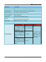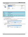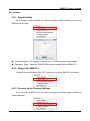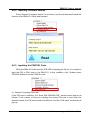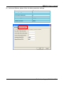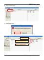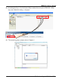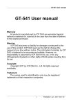
1
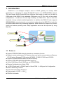
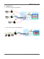
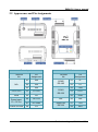
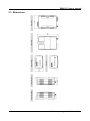
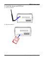
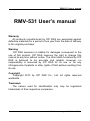
RMV-531 User’s manual RMV-531 User’s manual Warranty All products manufactured by ICP DAS are warranted against defective materials for a period of one year from the date of delivery to the original purchaser. Warning ICP DAS assumes no liability for damages consequent to the use of this product. ICP DAS reserves the right to change this manual at any time without notice. The information furnished by ICP DAS is believed to be accurate and reliable. However, no responsibility is assumed by ICP DAS for its use, or for any infringements of patents or other rights of third parties resulting from its use. Copyright Copyright 2013 by ICP DAS Co., Ltd. All rights reserved worldwide. Trademark The names used for identification only may be registered trademarks of their respective companies. 1 Publication August, 2014 Ver.1.02 RMV-531 User’s manual Table of Contents 1. Introduction ............................................................................ 3 1.1 1.2 2. 3. Hardware ............................................................................... 5 2.1 2.2 2.3 Specifications ........................................................................................................... 5 Appearance and Pin Assignments ............................................................................ 6 Dimensions............................................................................................................... 7 2.4 2.5 LED Indicators ......................................................................................................... 8 Install the antenna and SIM Card ............................................................................. 9 Installing the RMV-531 Utility ............................................... 10 3.1 3.2 4. 5. Features .................................................................................................................... 3 Applications ............................................................................................................. 4 Installing .NET Framework ................................................................................... 10 Installing the RMV-531 Utility .............................................................................. 12 The RMV-531 Utility operation description .......................... 15 4.1 4.2 Main Menu ............................................................................................................. 15 File Menu ............................................................................................................... 16 4.3 4.4 4.5 4.6 Connecting to the RMV-531 .................................................................................. 16 Parameters .............................................................................................................. 17 Download/Upload Parameters ............................................................................... 19 System .................................................................................................................... 20 Virtual com to access remote the parameters ..................... 23 5.1 5.2 The necessary software installed............................................................................ 23 Setting the VxServer and VxComm Driver ........................................................... 24 2 Publication August, 2014 Ver.1.02 RMV-531 User’s manual 1. Introduction RMV-531 is an intelligent multiport serial to 2G/3G gateway for industry M2M applications. It is designed for linking RS-232/485 devices to a GPRS/WCDMA network. The user-friendly Axiom Driver/Utility and VxServer allow users to easily turn the built-in COM ports of the RMV-531 into standard COM ports on a PC. By virtue of its protocol independence, a small-core OS and high flexibility, the RMV-531 is able to meet the demands of every network-enabled application. In addition, the RMV-531 also supports GPRS/WCDMA network automatic re-connection function when the RMV-531 is broke the GPRS/WCDMA network by something happened. M2M solution will improve the service quality and reduce operating costs. Many application areas can be improved by using RMV-531. RS-232/RS-485 RMV-531 GPR S /WC DM A GPRS/WCDMA Network VxComm Driver VxServer Software GP R RS-232/RS-485 S/W CD MA Public Fixed IP Internet RMV-531 GPRS/WCDMA RS-232/RS-485 RMV-531 1.1 Features Support GPRS/WCDMA network automatic re-connection function Support remote maintenance PLC devices that used serial communication as Siemens S7-200 series, Siemens S7-300 series, WP-8000, LP-8000, iP-8000 and XP-8000 Support WCDMA 850/900/1900/2100 MHz frequency Support GPRS 850/900/1800/1900 MHz frequency Virtual COM Extend Real COM Ports via GPRS/WCDMA Remote Configuration by Virtual COM 1 x RS-232 port and 1 x RS-485 port for Virtual COM. 1 x Utility port for Configuration Built-in Watch-dog Function Power Reverse Polarity Protection Power supply +10 VDC ~ +30 VDC DIN-Rail mountable 3 Publication August, 2014 Ver.1.02 RMV-531 User’s manual 1.2 Applications PLC remote maintenance application RS-232 RMV-531 PLC S/W CD MA PLC Software G PR S/ W C D M A GP R GPRS/WCDMA Network VxComm Driver Public Fixed IP RS-485 Internet VxServer RMV-531 PLC R GP CD S/W MA RS-232 RMV-531 PLC Remote serial devices monitor application M A User’s software D S/ W C RS-485 network G PR GPRS/WCDMA Network VxComm Driver Public Fixed IP Internet VxServer RMV-531 Anemometer Seismic sensor Flow meter 4 Publication August, 2014 Ver.1.02 RMV-531 User’s manual 2. Hardware 2.1 Specifications System CPU ARM Microprocessor SRAM 32 Kbytes Flash Memory 512 Kbytes WDT(watchdog) Yes 2G system Frequency Band 850/900/1800/1900 MHz Class 4 (2 W @ 850/900 MHz) Power class Class 1 (1 W @ 1800/1900 MHz) 3G system Frequency Band 850/900/1900/2100 MHz Power class Class 3(250mW @ WCDMA/HSPA) Serial ports Utility port RS-232: TxD, RxD, GND (use for device configuration and debug) COM1 RS-232: TxD, RxD, GND (use for communication with other devices) COM2 RS-485: D+, D- (use for communication with other devices) Baud Rate 2400、4800、9600、19200、38400、57600 and 115200 bps Power Protection Reverse polarity protection Frame Ground Protection ESD, Surge, EFT, Hi-Pot Required Supply Voltage +10 VDC ~ +30 VDC Mechanical Casing Plastic Flammability UL 94V-0 materials Dimensions (W x L x H) 91 mm x 132 mm x 52 mm Installation DIN-Rail Environmental Operating Temperature -25 ℃ ~ +75 ℃ Storage Temperature -30 ℃ ~ +80 ℃ Ambient Relative Humidity 5 ~ 95% RH, non-condensing 5 Publication August, 2014 Ver.1.02 RMV-531 User’s manual 2.2 Appearance and Pin Assignments RMV-531 Power Input Terminal No. COM Port Pin Assignment 01 N/A 02 N/A 03 N/A Initial.GND 04 Init.GND Initial 05 Init Power Input: 10 ~ 30 VDC 06 DC.+VS 07 DC.GND Frame Ground 08 F.G. N/A Terminal No. 01 D- 02 D+ 03 TxD1 04 RxD1 05 GND N/A 06 N/A Utility Port RS-232 07 TxD 08 RxD COM2 RS-485 COM1 RS-232 6 Pin Assignment Publication August, 2014 Ver.1.02 RMV-531 User’s manual 2.3 Dimensions 7 Publication August, 2014 Ver.1.02 RMV-531 User’s manual 2.4 LED Indicators There are three LED indicators to help users to judge the various conditions in the RMV-531. The description is as the following: (1) EXT (Red): The External Power LED indicated status whether the power is supplied or not. The description is as the following: The Power is active The Power is not active ON OFF (2) 3G : The modem LED(Green) can indicate the status Modem normal Modem fail Blanking pre 3 sec (2G network) OFF Twinkling twice per 3 sec (3G network) (3) STA (Orange): The system LED indicated whether the RMV-531 is normal of failed First Use No connected Connected Wrong PIN/PUK code OFF Blinking (0.5 sec) Blinking (1 sec) Blinking (50 ms) 8 Publication August, 2014 Ver.1.02 RMV-531 User’s manual 2.5 Install the antenna and SIM Card (1) Antenna installation (2) SIM card installation 9 Publication August, 2014 Ver.1.02 RMV-531 User’s manual 3. Installing the RMV-531 Utility 3.1 Installing .NET Framework It needs the runtime environment with .NET Framework 2.0 or above to execute the RMV-531 Utility in the PC. If there has .NET Framework 2.0 or above in the PC, the section 3.1 can be omitted. Microsoft .Net Framework Version 2.0: http://www.microsoft.com/downloads/details.aspx?FamilyID=0856eacb-43624b0d-8edd-aab15c5e04f5&DisplayLang=en Microsoft .Net Framework Version 3.5: http://www.microsoft.com/downloads/details.aspx?familyid=333325FD-AE524E35-B531-508D977D32A6&displaylang=en (1) Press “Next” to the next step. (2) Select the “I accept the terms of the License Agreement” and “Install” to the next step. 10 Publication August, 2014 Ver.1.02 RMV-531 User’s manual (3) The installation process would be going (4) After finishing the installation, press “Finish” to exit the program. 11 Publication August, 2014 Ver.1.02 RMV-531 User’s manual 3.2 Installing the RMV-531 Utility Plug in the shipment CD into the PC, Execute RMV-531_Utility_Setup_Vx.xx.exe. The installation figure is as follows: (1) Press “Next” to start the installation procedure. (2) Select the installation path. The default path is ” C:\ICPDAS\RMV-531_Utility”. Press “Next” to the next step. 12 Publication August, 2014 Ver.1.02 RMV-531 User’s manual (3) Select the “Start Menu Folder”, Press “Next” to the next step. (4) Select additional tasks. Press “Next” to the next step 13 Publication August, 2014 Ver.1.02 RMV-531 User’s manual (5) Click ”Install” to start to install the RMV-531 Utility (6) Click “Finish” to finish installing RMV-531 Utility 14 Publication August, 2014 Ver.1.02 RMV-531 User’s manual 4. The RMV-531 Utility operation description 4.1 Main Menu The main menu of RMV-531 Utility includes the following sections: Tool Menu Parameters Parameter Group Description Status Bar (1) Tool Menu: These tools include all the function operation of the RMV-531 Utility. The description is as the following: Project: The parameters of the RMV-531 can be saved as the project file. The operation functions include “New”, “Open”, “Save”, “Save as…”, and etc... Exit: Exit the RMV-531 Utility. COM Port: The COM Port number of the host PC connecting to the RMV-531. Connect: Connecting to the RMV-531. Download: Downloading the settings to the RMV-531 device. Upload: Uploading the settings from the RMV-531 device to RMV-531 Utility. System: Providing some system operations including ”Signal Quality”、”Reboot RMV-531”、“Recover Default Settings”、”Firmware Version”、”Input PIN/PUK”. (2) Parameter groups: There are four parameter groups in the RMV-531 Utility including: ”System” and ”COM Port”. 15 Publication August, 2014 Ver.1.02 RMV-531 User’s manual (3) Parameters: Show or set the parameters. (4) Description: A particular or minute account. (5) Status Bar: This bar can show the operation procedure of the RMV-531 Utility. From left to right, they are: 1. The used com port number. 2. Communication configuration of the COM Port. 3. The current status of the COM port. 4. The address of the RMV-531. 5. The result for operating the functions. 4.2 File Menu This tool provides users to operate the project file. It can save the RMV-531 configuration as the file or upload the settings from the file. It is convenient to manage a lot of RMV-531s. The explanation is as the following: New: Opening a new file. Open: Opening a exited file. Save: Saving the file. If the parameters are changed or save the uploading parameters from the RMV-531, you can use this function to save these configurations. Save as: Saving the file as another name. 4.3 Connecting to the RMV-531 For connecting to the RMV-531, you can follow the steps below. I. Select the COM port of the host PC and connect to the Utility port of RMV-531. 16 Publication August, 2014 Ver.1.02 II. RMV-531 User’s manual Press ”Connect” to connect to the RMV-531. If the connection is failed, check the COM port settings and wiring. 4.4 Parameters The parameters would be shown in the right of the windows if click the tree field in the left side of the RMV-531 Utility. Press the parameters’ “Value” filed can change these parameters as the following figure. 1.1.1 System There are 12 items in the system field below. 17 Publication August, 2014 Ver.1.02 RMV-531 User’s manual Parameters Description Net ID The ID of RMV-53. Read only Function VxComm function or Modbus TCP to RTU function Remote Server The remote VxServer server’s IP or domain name Remote Server Port The remote VxServer server’s Port Internet User name Internet user name Internet password Internet password Internet APN Internet APN (access point name) Virtual IP Virtual IP. Range: 127.0.0.1~127.255.255.254,This parameter can’t be the same with other device. Module Alias Module Alias. (max. 7 character) Heartbeat Time Heartbeat time. Range: 10 sec. ~ 65535 sec. Com End Method Com End Method Com End Param. Time: Fixed Time. It is as complete a data 2 ms~ 65535 ms when no data came at a fixed time Length: Fixed Length, Com End Param. It is as complete a data when the length of a 1 ~ 1000 data more than fixed length 2: Fixed end byte. It is as complete a data when receives the fixed 0 ~ 255 end byte. Like “CR” (0x0d) 18 Remark The RMV-531 will transmit a data when there is a data more than 1000 bytes. Publication August, 2014 Ver.1.02 RMV-531 User’s manual 4.4.2 COM Port The parameters of COM Port (Read only) Parameters Description Port COM Port name Data Bit 7 or 8 bits Stop Bit 1 or 2 bits Parity Bit None, Even, Odd Baudrate 2400、4800、9600、19200、38400、57600 and 115200 bps 4.5 Download/Upload Parameters I. Download parameters As the configuration is finishing, the function can download the parameters to the RMV-531 by clicking “Download” as the following figure. II. Upload Parameters “Uploading” button can upload the parameters from the RMV-531 as the following figure. 19 Publication August, 2014 Ver.1.02 RMV-531 User’s manual 4.6 System 4.6.1 Signal Quality Click “System->Signal Quality” can show the signal quality windows to know the GSM signal strength. Field Description: The strength is divided into 5 sections shown in percentage. Operation: Read:Read the GSMWCDMA signal strength from the RMV-531. 4.6.2 Reboot the RMV-531 Clicking “System->Reboot RMV-531” button can reset the RMV-531 as follows. 4.6.3 Recover to the Factory Settings It can recover the RMV-531 to the default settings by clicking “System->Recover Default Settings”. 20 Publication August, 2014 Ver.1.02 RMV-531 User’s manual 4.6.4 Inquiring Firmware Version Press “System->Firmware Version” in tool menu, and the window would show the versions of the RMV-531 Utility and firmware. 4.6.5 Inputting the PIN/PUK Code When the RMV-531 starts and the STA LED is blanking per 50 ms, it is needed to input the PIN or PUK code in the RMV-531. In this condition, click “System->Input PIN/PUK” button to set the PIN/PUK code. (1) Asking for inputting PIN code: If the PIN code is effective, the “Enter SIM PIN/SIM PUK” window would pop-up as follows. If the number of times for inputting the wrong PIN code is more than the allowed number, the PIN code would be ineffective. And the “PUK code” window would pop up. 21 Publication August, 2014 Ver.1.02 RMV-531 User’s manual (2) Asking for inputting PUK code If the PIN code is ineffective, the “PUK code” window would pop-up as follows. As the number of times for inputting the wrong PUK code is more than allowed number, the SIM card would be ineffective forever. Therefore, it is important to input the correct PUK code. 22 Publication August, 2014 Ver.1.02 RMV-531 User’s manual 5. Virtual com to access remote the parameters 5.1 The necessary software installed Installing .NET Compact Framework Installing VxServer Installing VxComm Drivr Installing RMV-531 Utility Download Microsoft .Net Framework Version 2.0: http://www.microsoft.com/downloads/details.aspx?FamilyID=0856eacb-4362-4b0d-8edd-a ab15c5e04f5&DisplayLang=en Download VxServer software: http://m2m.icpdas.com/VxServer.html Download VxComm Driver software: http://ftp.icpdas.com/pub/cd/8000cd/napdos/driver/vxcomm_driver/2k/ 23 Publication August, 2014 Ver.1.02 RMV-531 User’s manual 5.2 Setting the VxServer and VxComm Driver (1) Verify that the device has been connected up (2) Execute VxComm Utility, then click ”Search Servers” 24 Publication August, 2014 Ver.1.02 RMV-531 User’s manual (3) Select your device, then click ”Add Server(s)” (4) IP Range=> check “Maps virtual COM ports to “Port I/O” on servers. 25 Publication August, 2014 Ver.1.02 RMV-531 User’s manual (5) Advanced Options, please follow the below parameter settings Parameters Fixed value Keep Alive Time 1 Connection Broken 3 Connect Timeout 1 Command Port 10000 Virtual I/O Port 9999 26 Publication August, 2014 Ver.1.02 RMV-531 User’s manual (6) Tools => Restart Driver (7) Click “Restart Driver” RMV-531_Utility RMV-531 COM1 (RS-232) RMV-531 COM2 (RS-485) 27 Publication August, 2014 Ver.1.02 RMV-531 User’s manual (8) According the Port I / O of VxComm Utility to select the com port of RMV-531 Utility, then click “RMV-531 Utility => Connect” (9) The remaining steps, please refer to Chapter 4 28 Publication August, 2014 Ver.1.02 RMV-531 User’s manual Version Record Version By Date Description 1.00 Kane 2012/01/31 Release 1.01 Kane 2013/08/01 Modify Spec. 1.02 Kane 2014/08/08 Add Modbus TCP to RTU function 29 Publication August, 2014 Ver.1.02