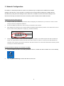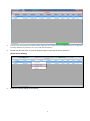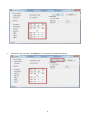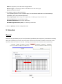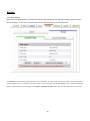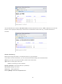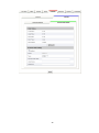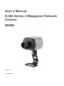
1
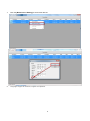
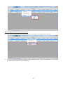
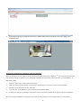
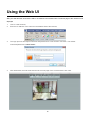
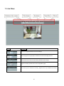
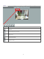
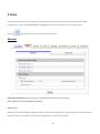
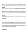
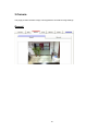
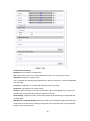
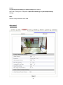
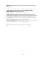
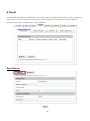
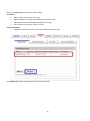
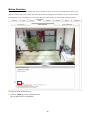
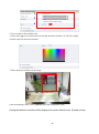
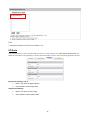
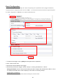
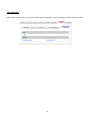
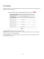
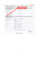
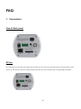
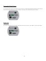
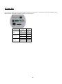
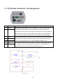
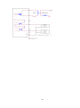
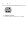
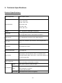
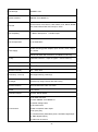
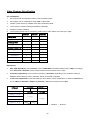
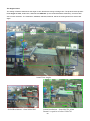
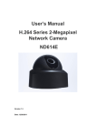
User’s Manual H.264 Series 2-Megapixel Network Camera N600E Version: 1.5 Date: 12/26/2011 Contents Notices ......................................................................................................................................................... 2 Introduction .................................................................................................................................................. 3 Installation.................................................................................................................................................... 4 Using the Web UI ....................................................................................................................................... 12 1. Live View ....................................................................................................................................... 13 2.Video ............................................................................................................................................... 16 3.Camera ............................................................................................................................................ 19 General ....................................................................................................................................... 19 Advanced ................................................................................................................................... 21 4 .Event .............................................................................................................................................. 23 5. Schedule ......................................................................................................................................... 29 General ....................................................................................................................................... 29 Storage ....................................................................................................................................... 30 6. Network.......................................................................................................................................... 33 General ....................................................................................................................................... 33 Advanced ................................................................................................................................... 34 SMTP (E-Mail) .......................................................................................................................... 35 DDNS ......................................................................................................................................... 36 7. System ............................................................................................................................................ 37 User ............................................................................................................................................ 38 Date & Time ............................................................................................................................... 39 Server Maintenance ................................................................................................................... 40 Log Service ................................................................................................................................ 41 8. Customize ...................................................................................................................................... 42 FAQ ............................................................................................................................................................ 44 1. Connectors ..................................................................................................................................... 44 View of Back panel .................................................................................................................... 44 DC-Iris ....................................................................................................................................... 44 Composite Video Output............................................................................................................ 45 Audio Out................................................................................................................................... 45 SD Card Slot .............................................................................................................................. 46 2. I/O Terminal Connector - Pin Assignment ..................................................................................... 47 Restore Factory Default Settings ............................................................................................... 49 3. Technical Specifications ................................................................................................................ 50 Product Specifications ............................................................................................................... 50 Video Streams Specification ...................................................................................................... 53 1 Notices This user manual is intended for administrators and users of the H.264 Series Network Camera, including instructions for using and managing the camera on your network. The use of surveillance devices may be prohibited by law in your country. It is the user’s responsibility to ensure that the operation of such devices is legal before installing this unit for its intended use. Before the Network Camera is installed, all the safety and operating instructions should be carefully read and followed to avoid damage due to faulty assembly and installation. This also ensures the product is used properly as intended. Heed all warnings Do not drop or strike this equipment Sensitive electronics inside the camera are vulnerable to excessive strike. Do not install the equipment near any flames or heat sources Excessive heat could damage this equipment. Do not cover cloth or to install this equipment in poorly ventilated places. Overheating could damage this equipment. Do not expose this equipment to rain or moisture. Do not touch the power connection with wet hands Risk of short circuit, electric shock or fire Do not damage the power cord or leave it under pressure Risk of fire or shock circuit To reduce the risk of electric shock, do not remove the Cover (or Back). No user-serviceable parts inside. Misusage, improper, and negligence could damage this equipment. Need to refer servicing to qualified service personnel. Do not continue to operate if there appears to be fault. If the unit ceases to function, contact qualified service personnel for help. All work related to the installation of this product should be made by qualified service personnel or system installers. 2 Introduction H.264 N600 Series Network Camera delivers superior H.264-AVC performance, state of the art design and function. N600 Series is specifically adapted for maximum performance indoor applications, such as commercial, banking, government buildings, schools, universities and airports. H.264-AVC video compression can lower bandwidth and storage requirements without compromising image quality; Motion JPEG is supported for increased flexibility, as well as multiple independent video streaming. N600 Series value-added features include; on-board video motion detection, SD slot for storage recording, and two-way audio. N600E, the PoE model, is available with full PoE (IEEE-802.3af) feature that supplies function of power to the camera via the network, eliminating the need for power cables, reducing installation costs and complexity. Consequently, N600 Series is “Best in Class” for maximum performance IP video surveillance systems, demanding superior image quality, ease of installation, and intelligent video capabilities. 3 Installation 1. Hardware Connection 4 2. Software Installation The following software is necessary for the proper display and use of the N600 from the Web site. The software will be available from the Software Package CD. IP Installer The IP Installer is used to locate and configure network cameras and video servers on the LAN. This utility is useful for conveniently configuring the network settings of the device, or for finding a device once the network settings have been modified. To install the IP Installer, from the Software Package CD UI, select IP installer, then follow the on screen instructions. XVID Codec An H.264 codec is applied for displaying the video stream and playing the recoded AVI files. If the video stream can’t be displayed or the recorded AVI files can’t be play on PC, install this software from the Software Package CD. VLC Though not necessary, this can be used for viewing the streaming without a Web browser. 5 3. Network Configuration IP Installer is a utility that provides an easier, more efficient way to configure the IP address and network settings of the devices. It even provides a convenient way to set the network settings for multiple devices simultaneously using the batch setting function. Moreover, IP Installer can save the network settings for all devices as a backup and restore them when necessary. NOTE: Default mode for N600 is DHCP. Preparation before IP Assignment 1. Always consult your network administrator before assigning an IP address to your server in order to avoid using a previously assigned IP address. 2. Ensure the N600 is powered on and correctly connected to the network. 3. MAC Address: Each device has a unique Ethernet address (MAC address) shown on the label of the device as the serial number (S/N) with 12 digits (e.g. 000429-XXXXXX). *0004290000 B1 4. Although the IP Installer is able to find and configure any N600 on the LAN except those that are behind a router, it is a good idea to set the host PC to the same subnet. In order to connect to the Web-based user interface of the camera, the host PC must be in the same subnet. For more information about subnets, please consult your network administrator. Using IP Installer to Assign an IP Address to N600 1. Once IP Installer has been successfully installed on the PC, double click the IP Installer icon on the desktop 2. Click the [Device Search] to search the device in the LAN. 6 3. From the list, select the device with the MAC Address that corresponds to the N600 that is to be configured. The MAC Address is identical to the unit’s S/N (Serial Number). 4. Double click the select item to open the Property Page or right click the item to select the [Single Device Setting] 5. Modify the network settings of the camera 7 6. After filling in the properties, click [Set] button to complete the configuration settings. 8 7. Click the [Batch Device Setting] to set several devices. 8. Language support for Chinese, English and Spanish. 9 Open the Web-based UI of the selected camera 1. To access the Web-based UI of the selected unit, run the View > Open Web on the menu bar. 2. For first time user, there will be a prompt to install the ActiveX control. Confirm the installation as it is required to view the video stream and some operations. 10 3. If the device has been configured correctly, the default Web browser will open to the home page of the selected device. Verify and Complete the Installation from Your Browser When browsing the Home Page for the first time with the Microsoft Internet Explorer TM , you must temporarily lower your security settings to perform a one-time-only installation of the ActiveX component onto your workstation, as described below: 1. From the Tools menu, select [Internet Options] 2. Click the [Security] tab and then click [Custom Level] button to see your current security settings. 3. Set the security level to Low and click [OK]. 4. Type the URL or IP address of your camera into the Address field. 5. A dialog box will pop up asking if the ActiveX control should be installed. Click [Yes] to start the installation. Once the ActiveX installation is complete, return the security settings to their original value, as noted above. 11 Using the Web UI Start your Web browser and enter the URL or IP address in the Address field. The Home page of the camera is now displayed 1. Launch a web browser, 2. Enter the IP address of the camera in the address field of the browser, 3. The login process will require username and password for a new session connection. The default username/password is admin/admin. 4. After authorized, the web will be directed to the main page of the camera with the live video. 12 1. Live View Button Description Click for more general/Advanced camera settings Select languages among English, traditional Chinese and simplify Chinese Check actual size to view the actual size (resolution) of the image Triggers manually a preset event in the configuration page Choose among the 3 streams for viewing,Digital PTZ is only available with stream 2 13 Button Description Full screen Listen the audio input from local end Talking function Record instant live video Snapshot the image 14 Configuration Pages List Video General Advanced Camera General Advanced Event Event Server Motion Detection I/O Ports Event Configuration Schedule General Storage Network General Advanced SMTP (E-mail) DDNS System Information User Date & Time Server Maintenance Log Service Customize Style Layout 15 2.Video This section describes how to configure the video streaming from the device, and the related camera image configurations. Users with Administrator or Operator authority are intended for these configurations. Click on SETUP button to enter in the configuration pages. General Video General Setting: Check each box to enable streams (max 3) for live viewing Note: Digital PTZ is only available with stream 2 OSD Setting Enable the On Screen Display (OSD) information. A line of text message (e.g. Camera Name or Position) and the date/time string are available to be selected for displaying or hiding on the images. 16 Digital PTZ is only available with stream 2 Choice the Stream 2, the web wills display the control panel to control e-PTZ function of N600 1 2 3 1: Zoom: Digital zooms in/out. 2: Pan Arrow: Click to control Pan function. 3: Step: Setting the speed of Pan function. (1、5、10) Advanced The Video Advanced setting page provides more detail stream configurations. These settings can affect video size, quality. The expected transferring performance must be under the condition of full network bandwidth Stream Setting: Note: 1:Configuration of stream 2 is the same as stream 1, but Stream 2 can only be set to 320x240 or 640x480, 2:Stream3 only RTSP path、image format and frame rate can be adjusted, the rest of the settings are fixed. RTSP Path The RTSP Path is the stream ID used for RTSP client streaming connection, such as VLC player. The default values are v00, v01 and v02 for the three streams respectively. The string can be any combination of number or capital/small letters. It cannot be empty however. 17 Resolution The resolution here describes an image size counted by width and height, e.g. 640x480, referring to pixel st resolution. The 1 stream can be set from more options of resolution; 1600x1200 (2 megapixels), 1280x720(HD), 800x600(SVGA), 640x480(VGA), 320x240(QVGA). While Stream2 has the options of VGA and QVGA, stream3 is in a fixed resolution, the QVGA. Video Mode This option allows the selection of two bit rate modes, the Constant Bit Rate (CBR) or Variable Bit Rate (VBR). CBR refers to the setting of a fixed Target Bit Rate (configuration in the rage of 64Kbps to 6Mbps) that would apply in the case of limited bandwidth or/and storage requirement. While CBR concerns a fixed data rate transmitting, the video quality is of high priority for VBR mode selected. VBR therefore is configured with the Quality Level (Standard, Good, Best). In general, CBR predicts the provided condition; if image activity requires higher bit rates than configured, the frame rate and quality would be affected as not likely to increase bandwidth (bit rate). In spite of the required recording storage estimation, VBR is by way of compensation that adjustable bit rate fits the actual image activity. Image Format H.264 and MJPEG are available for image format selection. The term, “image format”, is referring to compression / encoding technique. The selection of image format decides the performance of bandwidth and storage requirement. In the request of same video quality, H.264 contributes to less bandwidth and storage requirement, which is more efficient than MJPEG. GOP In H.264 video coding, GOP (group of pictures) describes how the different types of frames are arranged. The frame types implemented here are I-frame (full image information) and P-frame (motion-compensated difference information). This setting configures the GOP length which is the number of frames before next I-frame appears. Having more I-frames usually increases the stream size, and therefore more bandwidth and storage are required. Frame Rates The Frame Rates defines the number of frames that will be displayed per second. The frame rate setting can affect the target bit rate (bandwidth requirement) and storage requirement. Note: While multiple streaming is possible, each stream has its limitation and dependency to other stream. See “Video Stream Specification”. 18 3.Camera This page provides the basic image color appearance and further image settings. General 19 Camera General Setting Brightness: the luminance of image view Hue: refer to pure a pure color, or described by its name, such as red, green or blue. Saturation: intensity of a specific color The 5 correlates are referring image appearance in terms of color/vision. These are adjustable from this page. Contrast: the difference in color and light between parts of an image Sharpness: the sharpness of camera image Rotation: rotate the image, so it looks up-side down. This can be applied when camera unit must be ceiling mounted and the image is therefore reversed. Audio Setting: enable this option, so the video stream will be transferring accompanied with the audio data. Web Record / Snapshot Setting: define the location where snapshot images and video clips will be stored. The file name is referring to the prefix of the actual file name of each snapshot image or video clip generated. 20 Default: Set [camera general setting] and [audio setting] back to default Note: Will not change the configuration of [Web Record Setting] and [web Snapshot Image Setting] Save: Save the changes that have been made Advanced 21 White balance: the adjustment to compensate for different environments in terms of light source. Exposure: Anti-flicker setting for image sensor to fit the frequency of light (power) source. For instance, the power frequency is 50Hz for most European countries, while 60Hz is typically for US. This setting is therefore regionally different. Note: Default setting is 50Hz Max. Exposure Time: referring to the shutter speed. Max. Gain Control: the amplification factor for the incoming light. Infrared (IR) Cut Filter: the default is automatically switched according to light intensity. Normally, with plenty of light sources (or sun light), there can be infrared included. The filter is automatically switched “Enable”, to avoid the image sensor from receiving the IR signal. Color/Mono Mode: The default is automatically switched according to light intensity. It can also be forced to display color image even in a low light environment. Back Light Compensation: Backlight compensation is video gain done manually to correct the exposure of subjects that are in front of a bright light source Video External Output Format: the format of composite output, NTSC/PAL. 22 4 .Event Event Handling describes the configurations of event type and the corresponding actions. To have an insight into this function, a common example can be storing a captured image to a local storage or remote FTP server (Actions), when there is a Motion Event (Trigger Condition). Event Server 23 Click on the [Add FTP] to expand FTP server setting FTP Server: Name: Give a name for the FTP server Network Address: Input the network address of the FTP server Upload Path: Choose the desired upload path for events Port: Input the port number of the FTP server Login Information: Username / Password: Input the username and password of the FTP Click [Remove] to delete selected event servers (circled in blue) 24 Motion Detection A snapshot image shows the whole view of the camera covered. To select a motion detection area, click directly on the image, then change the size and position by dragging and drawing. Up to 10 motion areas (configurations) can be added in the list. Each detection area can be set with its own sensitivity value. 1 To add a motion detection area: 1. Click on [Add] to set up a detection area. (Set up panel will be expanded) 25 2 3 4 2. Give a name to this window area. 3. Select the trigger level and sensitivity for this detection window. (0~100, low~high) 4. Select color for detection window. 5. Draw detection window on the image. DefaultWindow x 6. Once everything is done, click on [Save] to save the configuration made. Configured detection window will be displayed in motion detection list. (Circled in blue) 26 Note: 1. Maximum number of detection window is 10. I/O Ports This model supports 2 photo-coupled relay inputs and 1 relay outputs, see “I/O Terminal Connectors” for detail pin description and application. The tab shows the status of them; with external trigger/alarm devices. Input Ports Setting 1 and 2: Name: The name of Digital Input1/2 Current State: Current Input state Output Ports Setting: Name: The name of relay output Current State: Current Output state 27 Event Configuration The Event Configuration is to assign the actions responding to the specified events (Trigger Conditions). The table lists the configured events. Click on “Add…” or choose an event from the list to expend the panel for detail configurations. “Remove” is to delete a selected event. 1 2 3 4 5 6 1. To add an event trigger, click on [Add] and setup panel will be expanded. 2. Give a name to this event. 3. Set the time interval between each trigger. 4. Set the time period for the trigger. Choose “Always” or “During time between” or “Never”. During time frame: Choose a day and the starting time then configure the duration time (168hrs = 24x7). For example if duration time is set to 168(hrs), it is the same as choosing “Always” Trigger types (conditions): Motion Detection: The configured detection area(s) for motion events. 28 GPIN: the physically connected external trigger/button. Manual Trigger: a virtual trigger button embedded on the web main page. Period: set the time interval 5. The trigger condition is Motion Detection. The responding actions can be “Upload images” and “Send Email Notification” and “Send Message Notification (TCP)”.and “Activate Output Port” Select Upload type: Store image to FTP (Remote) / SD Storage (Local) / send E-mail Activate Output Port: Activate Relay Output Send Email Notification: Send Email Notification Send Message Notification (TCP): TCP Message Notification 6. Click on [Save] to save the configuration mad 5. Schedule General Define the day (specified by days of a week) and time (specified by each single hour) for that will be recording during the scheduled period. User can select which video stream should be recorded, and the size of each sliced file. When the check box is ticked, recording process starts at the scheduled hours (red blocks). 29 Storage Local Disk Setting: Display the storage information, includes disk size info, type and status. The warning message (red text) shows when recording is on process; SD card should not be removed during the recording process. The “Browse” button allows viewing the list of recorded files. The web page will then be redirect to the root path of the SD storage (if one is inserted). The list includes couple of folders, the event images which contains all the still images captured by any event trigger, and folders specified by date where the recorded video files are located. 30 The recorded files are named in date time format, and the extension file name is “.h264”. While file is in h264 raw format, it can be played in VLC player. Note that the recorded file includes video only; no audio information is recorded. Remote Disk Setting: Display the storage information, includes disk size info, type and status. If you want to access remote disk, you can choice Remote Disk Setting and tick Enabled item Action: If you want to access remote disk, please choice Mount item Type: NFS: The disk type of the Linux SMBFS: The disk type of the windows Remote Disk Path: Connection path (ex: ip address) User Name: Setting user name Password: Setting password Click on [Save] to save the configuration mad 31 32 6. Network The IP Camera acts as one of the network devices. It is therefore allowed “IP” to be assigned, so certain network functionalities can be implementable within this device. This section describes these configurations. Fundamentally, for instance, the IP assignment of the device can be done via DHCP server, manually fixed IP option or PPPoE to obtain IP from service provider. General Device IP configuration, includes DHCP, Static IP setting and PPPoE. “Enable ARP/Ping” enable device to accept ARP or ping packets from the network. Disable this option may provide extra security from intentional ping. PPPOE: The point-to-point protocol over Ethernet (PPPOE) is a network Protocol for encapsulating point to point frames inside Ethernet frames. 33 Advanced Enable or configure other network functions. Enable or configure other network functions. NTP: Configure a NTP (Network Time Protocol) server, so that the device system date and time can be synchronized with a specified Time Server. This configuration is provided for one of the potions of system date/time adjustment. HTTP: set the HTTP port that will be applied for Web UI access. RTSP: set the RTSP (Video) port for video data transmission. UPnP: Enable UPnP, so that the device can be discovered in an UPnP Compliant Network. NAT Traversal: Enable NAT traversal, so that client from Internet can have access to the devices behind the Router. Note: with UPnP enabled, the IP Sharing device (Router) capable of UPnP function will automatically be noticed with the device’s NAT port. 34 SMTP (E-Mail) Configure an email host in the device that will send email on behalf of the configured email account in a circumstance like sending an email notice to a specified mail address (Event Configuration). Sender: Complete the Mail Server, Server Port, Authentication information (if required) and the sender’s email address. Receiver: The receiver email address 35 DDNS Dynamic DNS configuration; the network device can be assigned and accessed with a host name instead of IP address by registering this service (Internet access required). Host Name: Assigned name that will be used for access to the device User Name/Password: Account authentication for logging to this service Update Time: Periodically, the device updates its access info to sever in the configured time. Response: the device responds the connection info. 36 7. System Information Lists of System and Network configurations 37 User Login users for Web access and operations; authentication required. The Check box is for anonymous logging on to the live view page. Logging for further configurations will still require user name and password. Follow the conditions shown to add different users with different authority. The default username and password is admin/admin respectively. 38 Date & Time System date/time configuration. Options of synchronizing with PC and NTP server are provided for automatic adjustment. 39 Server Maintenance This page provides tools for system maintenance; Reboot and Load default settings, as well as functionalities of launching upgrade process, backup/restore user settings and language defines. 40 Log Service Most system operations and / or process will be kept in a log system. The link provides the review of these records. 41 8. Customize This page provides the function of adjusting the look of live view page. There are two types of layout settings; use default look or use custom settings. Use Default Look: the default layout of live/configuration pages Use Defined Links: Web link(s) will be presented on the live page when enabled. It can be a link to another IP camera for instance, or other preferred web link. Use Custom Settings: The modifications allowed are change of Background / Text Color, Background picture, Title, Description, Logo and etc. 42 43 FAQ 1. Connectors View of Back panel DC-Iris For replacement of lens that comes with auto iris (DC-Iris), this connector provides power to electronically control the iris. In this case, the amount of light going through the lens then camera inside is automatically regulated. 44 Composite Video Output The composite video signal is retrievable from this connector. It is BNC (Bayonet Neill-Concelman) type as the end of both camera and terminal device, like TV Monitor or Recorder, with coaxial cable linked in between. Audio Out The 3.5mm audio stereo jack is for audio output that comes from a client PC. See “Talk” in “The Live View Page”. 45 SD Card Slot This connector allows SD type (includes SDHC) storage to be inserted in. The table below lists the SD/SDHC cards that have been approved compatible for this IP Camera device. Manufacturer Apacer Transcend SanDisk Type Capacity SDHC 8GB SD 2GB SDHC 8GB SD 2GB SDHC 8GB SD 2GB 46 2. I/O Terminal Connector - Pin Assignment Pin Function Description 1 COM Digital output implementation; Pin2 to COM (Pin1) is a Photo-coupled relay on 2 Relay-No Normal Open status. External device can directly connect to the terminals. However the current that will go through the 2 nodes must not exceed 130mA. An external “Relay” can also be connected to the terminals as an implementation. In this case, current (or/and voltage) limitation is specified by the external Relay. 3 GND Two sets of Digital Input, DI1 and DI2; the internal device is also photo-coupled 4 DI1 electrical relay. In practice, the external device can be simply an On/Off switch. 5 DI2 Two sets of On/Off switch can be connected as different trigger source. 6 12V An extra power entry for the camera device; or if power is supplied from the DC 7 GND jack, Pin6 can provide 12V power output. This power can be supplied for the external “Relay” device. The Pin7 is the same ground as Pin3. 47 48 Restore Factory Default Settings In some cases, system does not respond to any operation, this process gets the unit back to initial status, so that it can be reconfigurable for up and running again. To restore factory default, follow the steps below: 1. Unplug the power jack to turn off the camera 2. Insert a pin into the reset hole Sense a button and keep it pressed until instructed to release. 3. Plug in the power jack to turn on the camera. The power LED will start flashing in a short while. 4. Release the pin when the LED starts quick flashing. The device should be set back to factory default. 49 3. Technical Specifications Product Specifications Video Compression H.264 / Motion JPEG UXGA: 1600x1200 HD720: 1280 x 720 Video Resolution SVGA: 800 x 600 VGA: 640 x 480 QVGA: 320 x 240 Bit Rate 64K ~ 6M bits/sec (CBR/VBR configurable) 30 FPS @ HD720/ SVGA/ VGA/ QVGA, Frame Rate 15 FPS @ UXGA at both H.264/ MJPEG resolutions 1/3” 2 Megapixels Progressive Scan CMOS Sensor Image Device Fixed Lens, CS Mount , IR correction, Focal Length 6.0mm, Lens Type F2.4 IR Cut Filter Removable IR Cut Filter Minimum Illumination 1.5 Lux @ F2.0 Multi-Stream H.264 and Motion JPEG, controllable frame/ Video Control bitrate(bandwidth),VBR / CBR control , RTSP Path, Digital PTZ to choose image area Image Adjustment Trigger Brightness, Saturation, Sharpness, Exposure control , White balance, Backlight compensation, Rotation GPIN, Motion detection, Manual Trigger File upload via FTP, E-Mail and SD storage Event System Action Alarm Notification via E-Mail External output activation Video buffer Pre and post alarm (F/W to be upgrade) 50 Local Storage SD/SDHC card Network Interface 10BASE-T/100 BASE-TX Protocols HTTP,HTTPS, TCP/ IP,IPv4, UDP, SMTP, FTP, DHCP, DDNS, NTP, DNS, ARP,RTSP, RTP, Bonjour, UPnP Audio Capability 1 x Built-in Microphone, 1 x Audio output Audio Compression u-Law PCM 8Khz AC/DC switching power adapter, input: AC100 ~240V, output: Power Supply DC 12V/2A Built-in PoE IEEE 802.3af Class 3 (for N600E model only) Security Password Protection , Https encryption , User access log Power Consumption 5W Operation Temperature 0 C ~ 50 C Operation Humidity 20% ~ 80% RHG Dimension (L x W x H) 85mm(W)x78mm(L)x70mm(H) Net Weight Camera only 370g/ Camera with Stand 510g Operation Platform Microsoft Windows 2000 / XP/ Vista Browser IE 6.0 above Certification Report CE/FCC, ROHS,WEEE o o 1x DC IRIS connector 1x RJ45 10BASE-T/100 BASE-TX 1x Default setting button 1x SD card socket I/O Connectors 1x BNC composite video output 1x DC jack (12V) 1x Terminal blocks (Alternative power,12V/GND, Digital input x2, GND, Digital output) 1x Audio line out,3.5mm 51 1 x CD (manual and software) 1 x QIG Package Contents 1 x Terminal block 1 x Stand for mount 1 x AC/DC Power Adapter (Not included for N600E model) 52 Video Streams Specification The availabilities 1. Each stream can be switched to either H.264 or MJPEG mode. 2. Each steam can be configured to either CBR or VBR mode. 3. Stream1 (main stream) is available from all the resolutions listed. 4. The maximum resolution setting for Stream2 is 640x480. 5. Stream3 is fixed in 320x240. 6. The maximum frame rate for transferring 1600x1200 is 15fps. Others can reach up to 30fps. STREAM1 STREAM2 STREAM3 Encoding Mode H.264 / MJPEG V V V V V V Transferring Mode CBR / VBR Resolution @ Max. FPS 1600x1200@15 V 1280x720@30 V 800x600@30 V 640x480@30 V V 320x240@30 V V V Dependency 1. Max. FPS dependency: when Stream1 is set to 1600x1200, the maximum frame rate is 15fps. Accordingly, both Stream2 and Steram3 can be configured with the frame rate from 5 to 15 fps. 2. Resolution dependency: The maximum resolution of Stream2 is depending on the resolution setting of Stream1. When Stream1 is set to 320x240, Stream 2 is limited in 320x240. 3. Frame rate independent: Frame rate setting for each stream can be independent, for instance, Stream2 can be set 15fps and Stream3 is 30fps while Stream1 (1280x720 or below) is set to 5fps. STREAM1 1600x1200, 5~15 fps STREAM2 640x480 320x240 5~15 fps STREAM3 320x240 (fixed) 5~15 fps 1280x720, 5~30 fps 800x600, 5~30 fps 5~30 fps 640x480, 5~30 fps 320x240, 5~30 fps 5~30 fps 5~30 fps Note the resolution setting must follow the sequence: Stream1 ≧ Stream2 ≧ Stream3. 53 The Angle of View The setting of Stream1 determines the angle of view, therefore the range of image view. The pictures below present the 3 ranges of view, 1600x1200, 1280x720 and 960x720* (is not existed/selectable resolution), and the actual view of each resolution. The resolutions, 800x600, 640x480, 320x240, will be the scaling down from actual view angle. Actual View Angles Scaled Resolutions – from 1600x1200 Scaled Resolutions – from 960x720, when Stream1 is equal to or below 1280x720 54