1
WWW.AMPLADY.COM
Scanned by TA2ST
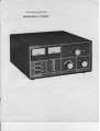
lntroduction
The DenTronDTR-2000LLinearAmplifieris a conseruatively
designed
2000Watt PEP160-15meter
amplifierof uniquedesign.Throughyearsof designing
linearamplifiers,
DenTronRadiohasgreatlysimplified the circuitryof the DTR-2000L,buildingin yearsof reliabilitybasedon the experience
of our worldfamousMLA-2500series. The incorporationof a single8877 la tube till now usedalmostexclusivelyin
broadcasting
applications)makesthe DTR-2000La no-compromise
unit featuringthe most powerfulfinal
tube ratingallowedundercurrentFCCregulations.
. . 1500Wattsplatedissipation!
The DTR-2000Lhas beenfully testedat the maximumlegalAmateurpowerlimit on all modes;SSB,
CW,SSTV,RTTY, as well as undercontestconditions.The unit coversall the AmateurBandsfrom 1.8 to
21.45OMHz, alongwith most MARS operatingfrequencies,
without modifications.With factory modifications, the DTR-2000Lwill operateon any frequencyfrom 1.8 to 35 MHz,strictly for commercialapplications.
A single8877 externalanodeceramicmetal triode is usedin the DTR-2000L,operatingin grounded
grid. A built-incontinuous
duty powersupplycompletes
the unit,capable
of either117V or 234Voperation,
although234V line voltageis recommended.Coolingof the unit is accomplished
throughan EIMAC specipowertransformer,
fied pressurized
hi-lo powerswitching,
chamberand chimney. A vacuumimpregnated
dual metersfor monitoringplate voltageand current,and modularconstructioncompletethe DTR-2000L
package.
Please
be certainto completelyreadthis manualbeforeoperatingyour new DTR-2000L.
U. S. Amateurregulations
limit the useof high poweredamplifierssuchasthe DTR-200OL
to licensees
of GeneralClassor higher.
WWW.AMPLADY.COM
Theory of Operation
After the DTR-2000Lis hookedup to an AC power sourceand turned on, power is appliedto the
power transformer.This appliespowerto the Amperitetube which keepsthe unit from beingkeyedfor 3
minutes. Also, power is suppliedto the B+ and 12 volt sectionsof the unit. The B+ sectionis a standard
voltagedoubler,the only differencebeingthat the transformer
hasa tap for SSBwhich is highestvoltageand
from relayK2. RelayK2 alsoselectsthe approCWwhich is about 30% less. Thesetwo voltages
areselected
priatezenerdiodefor SSBor CWoperation.
Platecurrent is measured
acrossB- to groundthroughR18,voltageis measured
through R6, R7, R8,
and R9 to ground. SSBis about27OOVDC andCWis about1800VDC.
After the readylamp is lit, control of the unit is accomplished
throughthe standbyswitchon the front
panel. A path to groundis requiredfor keyingthe amplifier.
Signalis appliedto J2 and passes
to J1 throughK1, if the unit is in standby.lf the unit is out of standby,
signalgoesfrom J2 through FL-l (matchingdwice) to.t5 on the tube box. Now, the signalgoesthrough
two .01 discceramiccapacitors(CG& C7) to cathodeof the 8877tube. Cathodebiasis controlledby R1 in
whetheryou're operatingSSBor CW. CW is 24 volt zener,SSBis 8.9 volt
standby,or D2 or D3 depending
zener.This is donethroughKl and K2 relays.
The gridsof the 8877 tube are groundeddirectlythroughclipsmountedinsidethe tube box. Outputof
the 8877 tube passes
througha parasiticchoketo C15. B+ is appliedto tubethrougha two stageplatechoke
circuit (RFC2,RFC3,C13, and C14). Amplifiedsignalgoesto a highlyefficientpi-networktank circuit
consistingof Cl8, L1, L2, and C21. Thereis only addedcapacitance
on the tune and loadcontrolsfor 160
meteroperation.
ALC is obtainedfrom the cathodeof the 8877tubethroughC8 andC9. The polarityof the ALC circuit
is set by Dl. As shownin the schematic,
ALC is negativegoingin the DTR-2000L. lf positiveALC is required,reverse
diodeD1.
WWW.AMPLADY.COM
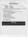
Specif ications
FrequencyRanges:
160 MeterBand
80 MeterBand
40 MeterBand
20 MeterBand
15 MeterBand
1.8- 2.5 M Hz
3.45- 4.6 MHz
6.00- 9.0 MHz
11.00- 16. 0 0MHz
20.95- 23.50MHz
just outsidethe AmateurBands. (With properFLI
The DTR-2000Lwill cover most MARS frequencies
and bandswitchmodification,the unit will alsocoverthe 10 meteramateurband.
Modes: USB,LSB,CW, RTTY, SSTV
PowerRequiremenr:234/117VAC 5O/60Hz
RF DrivePower: 125Wattsmaximum,and 65 WattsRMSminimumfor 1 KW DC input.
DC PlateVoltage: SSB {ldle+ 2500Vapproximate}
CW (ldle+ 1800Vapproximate)
Duty Cycle: 100%SSB,CW, RTTY, SSTV
Input lmpedance:50 Ohmsnominal
Input VSl\lR: 1.5to 1 average
Output lmpedance:5OOhmsnominal
AntennaloadVSIIVR:3 to 1 maximum
ALC: negativegoing,adjustablefrom rearpanel.
Emissions:
IMD - greaterthan30 db down
Spurior.rs
Harmonics- greaterthan 40 db down
FGCType Accepted
x D 14Y2"
Size: H 7To"xW 14Y2"
Weight: {including8877154pounds
3
WWW.AMPLADY.COM
Gautions
1.
Makeno attempt to put the DTR-2000Lin serviceoutsideof the cabinet. Contactwith voltagesin this
Amplifier can be fatal to the humanbody.
2.
Neverattemptto operatethe DTR-2000Lwith drivepowerof morethan 125 Watts!
3.
Neverattempt to operatethe DTR-2000Lwithout first connectingit to an antennawith an SWRof less
than 3:1, or a 50 Ohm dummy load of sufficientpower handlingcapacityor seriousdamagemay result
to the amplifier.
4.
Elo not, under any circumstances,
operatethe DTR-2000Lfrom a 117V lightingcircuit because
the circuit conductorsare not largeenoughto safelycarrythis load.
5.
Neverrun Amplifier from an extensioncord.
6.
Do not attempt to changejumper connectionson back of the Amplifier without firct removingpower
plug from the DTR-2000L.
7.
Do not ooverthe top of the DTR-2fllOLwith books,pape6 or other piecesof equipmentor overheata:rg
may result.
8.
Do not usedifferenttuning procedures
other than indicatedin this manual.
9.
Whencleaningthe DTR-2000L,neverblow high prcssureair directly into the fan blades. Spinningthe
fan at higher speedsthan it was designedfor can causedamageand lrcezethe rotor assemblyof the fan.
Usebrushin cleaningfan assembly.
I
I
I
4
Operating Features
1.
Continuousmonitoringof D.C.platevoltageand D.C.platecurrentvia two front panelmeters.
Standby/operate
switch.
3.
CW/SSBpowerswitchto providemaximumoperating
efficiencyat 1 KW and2 KW PEPinput to amplifier.
4.
Mandatory3 minutewarmupfor longtube life.
8877 EIMACtriode ratedat 1500Wattsdissipation,
yieldsa comfortablesafetymarginand insuresmaximumtubelife.
Unpacking lnstructions
Carefullyremoveyour DTR-2000Lfrom its packingcarton. Makesurethereis no damage
from shipping.
lf thereis any evidence
of damage,
notify the delivering
shipper,fully describing
the damage.
Fill out the DenTronRegistration
Cardincludedin the informationpackage
and return it to DenTron.
Do not destroythe packingmaterialsinceit will be usablelatershouldyou requirefactoryserviceor wishto
transportthe amplifierfor any otherreason.
In general,
the locationof your DTR-2000Lis not criticalaslongasyou makesurethat thereis adequate
air flow at the back, top and sidesof the case. Freshcool air entersfrom the back,throughthe fan, and
exhaustthroughthe top andsidesof the cabinet.
WWW.AMPLADY.COM
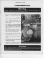
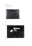
Tube lnstallation
l;
1.
Make sure that the AC power cord is not
pluggedinto an AC source before going
on.
2.
Removethe top cover of the DTR-2000L
with threescrewson both uppersides.
3.
Unpackthe 8877 tube and inspectit, making sureall pins are striaghtandthereis no
shippingdamage.
4.
Align the 8877 pins with the tube socket
(with the largepin orientednearlystraight
up) and carefullyinsert. lf too muchresistance is felt remorethe tube andcheckfor
bent pins.
After mounting the 8877 in its socket,inspect the teflon chimney and mounts to
makesurethey aremountedsolidly.
Ir
l,
6.
Installthe platecapconnectorandcarefully
tightenthe clampscrew.(Caution: Do not
overtighten).
7.
Unpack and inspectthe Amperitetime delay relay.
8.
Align the time delay tube pins with the
socketand carefullyinsert.
9.
Reinstall the DTR-2O0OLtop cover and
proceedto the next set of instructions.
WWW.AMPLADY.COM
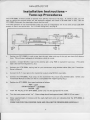
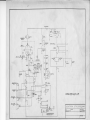
lnstallation lnstructions Tune-uF Procedures
The DTR-2O@Lis factorywired to operatetrom234 AC nominalat 15 amps. lf 117ACis used,you will
haveto rewirethe terminalblock per the schematicdiagramand installa 30 AMP 250 V fuse. Seethe
DTR-20@LSchematic
for attachinga plugto the linecord.
117 VAC operationis not recommended
unlessyou havean independent
117 V line with at leasta 30 AMP
breakeror fusein the servicebox. For 117VACchangeover,
seepage8.
1.
Positionthe DTR-2000Lin sucha way that the rear,sides,and top of the unit areclearof all obstructions. Thiswill assure
adequate
air circulation,which is a must.
2.
Connecta known 50 Ohm load to the antennajack using RG8 or equivalenttype coax. (Thesafest
loadis the DenTronBig Dummy,etc.)
3.
Connectthe DTR-2000Lkeying leadto your transmitterusingshieldedcables(Seeyour Transmitter
Owner'sManual).
4.
Connectthe R.F. input jack to the transmitteroutput using50 Ohm coaxcable.
5.
Connectthe DTR-2OOOL
ALC output to the transmitterALC input usingshieldedcable. (Checkyour
goingALC.)
TransmifterManualto makesurethat it is compatiblewith negative
6.
Positionthe DTR-20(X)L
front panelsritchesasfollows:
7.
P WR- OFF
STDBY/OPERATE
- STANDBY
O/V/SSB CW
Insertthe AC plugon the DTR-2000Lpowercord,into the appropriate
AC outlet.
8.
Turn the main powerswitch"on". Platevoltageshouldreadapproximately1800V DC on meter!
9.
Allow approximately3 minutesand the readylight will come on indicatingthat the DTR-2000Lis
readyto tune.
FROMTHIS POINTON. EXERCISE
CAREAND FOLLOWTHE PROCEDURES
CAREFULLY.
-/
CAREFULLY.
CAREAND FOLLq'UTHE PROCEDURES
FROMTHISPOINTON, EXERCISE
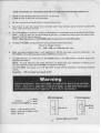
1.
(160M through40 Ml Setthe loadcontrolat 1 on the scale.
( 20 M through15 M) use3 on the loadscale.
2. Setthe tunecontroland bandswitchto the bandbeingtuned.
output of exciterto achieve50
3. Tune exciterto your input powerthat is normallyused! Now decrease
Watts. (Usecarrierdrivecontrol!)
4.
Tune DTR-2000Lfor maximumoutput in CW positionon a wattmetersuchas the DenTronW-2Wattdrivelevelcontroland retuneamplimeter. 1 KW DC input will not be achiaredat this point. Increase
fier until 1 KW DC input is achieved.
NOTE: Gheckthe position of the CWSSBswitch to makesureit is in the CW position.
5.
andexcitertuning,usingthe followingexample:
RecheckDTR-2m0L tr.rning
(Currentx Voltage= Powerl
Ex.: 1500x .666ma= l(XX)WattsDGinput
6.
When you havecompletedStep V and reachedthe 1 KW DC input lwel, unkey the transmitter. The
600 Wattsof powerout.
approximately
DTR-2000Lwill be delivering
7.
For SSB operationyou needonly put the CW/SSBsritch in the SSBposition,and selectproperside
bandon your exciter.
NOTE: For best efficiencyand lowest distortion yor should load your transmitteras heavilyas yotl
normallywould and retunethe DTR-2000Lto maintain1 KW input.
The DTR-2000L will acceptup to 125 WattsPEPof drive without distortingor generatingunwanted
outputs.
Remenrber:1 KW is the legalinput poryerlimitl!!
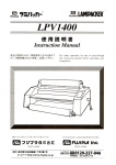
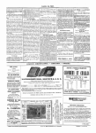
White
Black
Green
234 Volt Ooeration
1
Pins3 to 4
White= 1 sideot 234Y(117V)
Bfack= othersideot 234V (t 17V)
Green= Ground
rh
Pins2 to 4
3to5
;J
6
8
at
117 Volt Operation
WWW.AMPLADY.COM
r
v4
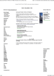
WWW.AMPLADY.COM
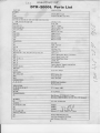
DTR.2OOOLParts List
P A RTNO .
T UB E S :
V1
T Dl
CAPACITORS:
D E S C R IP TION
EIMAC8877Triode
Amperite 372Min T.D. Relay
cl , c2, c3, c5, c6, c7, c10.cl 2. C42,C43,cr', , @5,
Ql6,andC22throughC33
c8, @
.01Disc,I KV
47 pf. S.M.
.001F. T. Caps.
150uf at 450 VDC
500pf,20 K V
600 Uf at 25 VDC
1000pf, 5 KV
200 pf, 5 KV
250 pf Variable
c 4, c 48, Cll
C34throughC41
c l3, C14,C2 0
a7
c l5, Cl9
c l6, Cl7
cl8
c21
\
\
\
800 pf Variable
RE S I S T O R S :
R1
R2
R3, R4
R5
R6, R7, R8
R9, R10,Rl1 , R l 2 , R l 3 , R 1 4 ,R t5 , R 1 6 ,R 1 7
Rl8
Rf c - 1
Rf c - 2, Rf c - 3
Rf c - 4
Rfc 5
Ll. L2
47K,2W
\
r0 0 K , w
2 PoT
\
27K ,Y .W
100Ohm,2W
1 Meg,5 W , 1%
\
100K,2W
FactoryMadeMeterShunt,.133Ohms
(\l
\
Factory Made Toroid - Rfc
Factory Made Plate Choke
2.5 Mh. Rfc
8.5 uh Choke
\
Factory Wound, Tapped Loading Coils
ParasiticChoke
4 T, * 18 W i reon R 5
RELAYS:
K T ,K 2
S1ATITCHES:
12 V, Cont. Relays
$Jvl, sw2, s1'v4
SPSTRockerSw.
s:w5
Interlock 9ritch
S:W3
5 Pos.BandStW
CONNECTORS:
J1,J2, J3,U
--S
\
q
SO239CoaxGonneqtor
RCA Connector
INDICATORS:
t1,t2,t3,t4,t5,t6,t7
12 V Lanps, *382
METERS:
M l, M 2
T RA NS F O R M ER :
0rl ma Meters
T1
DuafPrimary1117l234VACl.
Triote
(600v& gmv, nvt (5v Fitl, (lA/ c."troD
secondary
BLOTTVER:
B1
DlO DE S :
Dl, Dl6, D1 7 ,D 1 8
117V A C ,75C FMFan
1N'tO07
1N3321
D2
D3
JLl
(1
n
Fl /, H
1N3308
"A 1- ( t'n
Silicone
H.V.Diode,toobt f ttr5 arnp
D4 throughD15
MISCELLANEOUS:
F Ll
F1
FactoryMadeMatchingCkt.
LineFuse,30 Amp at 117VAC
and 15 Amp at 234 VAG
I
c.J
17
st1
PAR'3ITiC
CHOKE
!s-12!
$
*iE*-l
czl
asE_
as ila
Rrc V
I
l.ror
eg{*t
^#t-
WWW.AMPLADY.COM
rE*fr
*-'5f-
DENTRON
*3a2 sl
sw l
DTR 2OOOLAMP.
l-----
_ Lc2o-o!-,
-----l
@+
H V oU T
,ef
.av
**i*
@.F3qjEl.EljL
llSo "
@ 650
.!L=l
ll1 (}"r*
_lseJJ_EJI_ 5 l+
-
rr
T
W
=t-q
r*it
I
u/lRlNe
Fae
RF.tl
ltp.
tN 4 o o 1
1a!v^f.
* * or rrnu ors r nrc l o.;f * lFruff!l--4.p.-ag*rs-ert
d"t2tl
)t4V
- ,,/T:
Jgg\l.tt
I
I
PRitiAnV
\
ISOV&
lletr +
f*tt
3SIL.LIIL
I=
-
,t /.',-' t
1..;/
o/..,
?C
').-'J rr.Q.,irs
6'a.I
DTR 2OOOL
CD-t 7c, a 2 J t/ t
T ta ta t
4.,
3z
7;8t7.."1
J2r"-;'r.
Jc
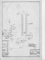
H,V.SUPPLY
WWW.AMPLADY.COM