1
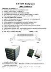
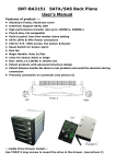
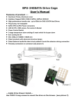
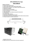
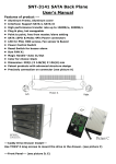
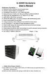
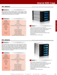
BPU-350SATA Drive Cage User’s Manual Features of product -- Aluminum Frame, Aluminum cover Interface: Support SAS-I, SAS-II, SATA-I, SATA-II, SATA-III High performance transfer rate : up to 6Gb/s for SAS & SATA hard drives Plug & play, hot swappable SATA 15Pin & 4Pin Power connectors LED for P/S , HDD access, Fan sensor & Buzzer Power Control Switch 3-stage temperature alarm settings & reset switch for buzzer alarm 8cm cooling fan X1 Dim: 207(L) X 126(W) X 146(H) mm Patent products with advanced structure design Patent balance handle-No skew in/out problem & avoid the abrasion during connection Precisely connection on connector (see picture A) ---Caddy Drive Drawer Install--Use TM#6*4 long screws to mount the drive on the drawer. (see picture C) ---Front Panel--- (see picture D, E) D.1--- D.5 (HD1~HD5, push On\off Power sw) D.6--- Reset Switch for buzzer alarm and Overheating Press the Reset Switch to stop the alarm, and Overheating LED goes off. D.7--- D.11 Power and HDD access LED Power on, LED indicates Green. Orange color blinking for HDD access) D.12--- Overheating LED When overheating occurs, the buzzer alarms (default setting: 60 and the temperature LED turns red, meanwhile, buzzer is alarming and LED is blinking). D.13-- Fan sensor LED: LED is indicating Green when it is Picture D working. When the fan failed, LED turns Red. D.14--- Carrier Safety Lock The safety lock safeguards the hard disk in the correct position and prevent it bouncing out while HDD is working. (see Picture E) POWER1: 4pin Power connector Picture E ---Rear View--- (see picture F) POWER2: 15pin Serial ATA data Power connector [*If your power is not from SATA 15pin connector, then, use the 4pin power connector, the 4pin power will automatically be convert to SATA power. (Note: Can mix using 4pin and 15pin powers) HD1—HD5: 7pin Serial ATA Signal connector lJP1: Temperature setting jumper lJP2 & J4: Extension function jumper FLR: Fan failure detection (red) FL+: Fan failure detection (+) FLG: Fan failure detection (green) RST: Reset Switch for buzzer alarm and Overheating LED TLR: Temperature detection (red), 5V+: 5V Power TLG: Temperature detection (green) GND: Grounded PL1- ~ PL5-: Ext Power LED detection (-) HL1- ~ HL5-: Ext HDD LED detection (-) VCC1- ~ VCC5-: Ext 5V Power (+) J5: FAN RPM HIGH (3600 rpm) & LOW (2800 rpm) Options Picture F