1
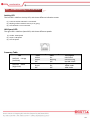
Embedded System MEB-7810 Always at the forefront of innovation User Manual 1 Copyright This publication contains information that is protected by copyright. No part of it may be reproduced in any form or by any means or used to make any transformation adaptation without the prior written permission from the copyright holders. This publication is provided for informational purposes only. The manufacturer makes no representations or warranties with respect to the contents or use of this manual and specifically disclaims any express or implied warranties of merchantability or fitness for any particular purpose. The user will assume the entire risk of the use or the results of the use of this document. Further, the manufacturer reserves the right to revise this publication and make changes to its contents at any time, without obligation to notify any person or entity of such revisions or changes. © 2011. All Rights Reserved. Trademarks All trademarks and registered trademarks of products appearing in this manual are the properties of their respective holders. FCC and DOC Statement on Class A This equipment has been tested and found to comply with the limits for a Class A digital device, pursuant to Part 15 of the FCC rules. These limits are designed to provide reasonable protection against harmful interference when the equipment is operated in a residential installation. This equipment generates, uses, and can radiate radio frequency energy and, if not installed and used in accordance with the instruction manual, may cause harmful interference to radio communications. However, there is no guarantee that interference will not occur in a particular installation. If this equipment does cause harmful interference to radio or television reception, which can be determined by turning the equipment off and on, the user is encouraged to try to correct the interference by one or more of the following measures: Reorient or relocate the receiving antenna. Increase the separation between the equipment and the receiver. Connect the equipment into an outlet on a circuit different from that to which the receiver is connected. Consult the dealer or an experienced radio TV technician for help. Notice: 1. The changes or modifications not expressly approved by the party responsible for compliance could void the user’s authority to operate the equipment. 2. Shielded interface cables must be used in order to comply with the emission limits. 2 Warranty 1. Warranty does not cover damages or failures that are raised from misuse of the product, inability to use the product, unauthorized replacement or alteration of components and product specifications. 2. The warranty is void if the product has been subject to physical abuse, improper installation, modification, accidents or unauthorized repair of the product. 3. Unless otherwise instructed in this user’s manual, the user may not, under any circumstances, attempt to perform service, adjustments or repairs on the product, whether in or out of warranty. It must be returned to the purchase point, factory or authorized service agency for all such work. 4. We will not be liable for any indirect, special, incidental or consequential damages to the product that has been modified or altered. Static Electricity Precautions It is quite easy to inadvertently damage your PC, system board, components or devices even before installing them in your system unit. Static electrical discharge can damage computer components without causing any signs of physical damage. You must take extra care in handling them to ensure against electrostatic build-up. 1. To prevent electrostatic build-up, leave the system board in its anti-static bag until you are ready to install it. 2. Wear an antistatic wrist strap. 3. Do all preparation work on a static-free surface. 4. Hold the device only by its edges. Be careful not to touch any of the components, contacts or connections. 5. Avoid touching the pins or contacts on all modules and connectors. Hold modules or connectors by their ends. Important: Electrostatic discharge (ESD) can damage your processor, disk drive and other components. Perform the upgrade instruction procedures described at an ESD workstation only. If such a station is not available, you can provide some ESD protection by wearing an antistatic wrist strap and attaching it to a metal part of the system chassis. If a wrist strap is unavailable, establish and maintain contact with the system chassis throughout any procedures requiring ESD protection. 3 Safety Measures To avoid damage to the system: • Use the correct AC input voltage range. To reduce the risk of electric shock: • Unplug the power cord before removing the system chassis cover for installation or servicing. After installation or servicing, cover the system chassis before plugging the power cord. Battery: • Danger of explosion if battery incorrectly replaced. • Replace only with the same or equivalent type recommend by the manufacturer. • Dispose of used batteries according to local ordinance. Before Using the System Before using the system, prepare basic system components. If the system comes as a barebone; that is, none of the key components, including processor, memory, and hard drive has been pre-installed as part of your purchase, you will need to at least ensure a compatible counterpart is located and installed. You will also need a few external system peripherals intended for the use of the system, a common pool with at least a keyboard, a mouse, and a monitor is thus suggested. 4 Table of Content Copyright .................................................................................................................................................................... 2 Trademarks .................................................................................................................................................................... 2 FCC and DOC Statement On Class A.............................................................................................................................. 2 Warranty ........................................................................................................................................................................ 3 Static Electricity Precautions ......................................................................................................................................... 3 Safety Measures ............................................................................................................................................................ 4 Before Using the System Board ..................................................................................................................................... 4 Table of Content ............................................................................................................................................................ 5 Chapter 1 General Information 1.1 Main Feature ........................................................................................................................................................... 7 1.2 Specifications ....................................................................................................................................................... 8 1.3 System Layout ................................................................................................................................................... 9 1.4 Indicators and Features .................................................................................................................................. 10 Chapter 2 Preparation 2.1 Before You Begin ...................................................................................................................................... 13 2.2 Precautions......................................................................................................................................................... 13 2.3 Open Up Top Cover............................................................................................................................................. 14 2.4 Removing Power Supply .................................................................................................................................... 15 2.5 Accessing Processor & Memory........................................................................................................................ 15 2.6 Accessing PCI Card .......................................................................................................................................... 16 2.7 Adding 2.5” SATA Hard Drive .......................................................................................................................... 17 2.8 Accessing CompactFlash Card ........................................................................................................................ 18 2.9 Changing Air Filter .......................................................................................................................................... 18 2.10 Adding Wall Mount Brackets ........................................................................................................................ 19 2.11 Adding Rack Mount Brackets........................................................................................................................ 19 Chapter 3 Operation 3.1 Turning On The System .................................................................................................................................... 21 3.2 Installing Operating System & Drivers ........................................................................................................ 22 3.3 Understanding LED Indicators ........................................................................................................................ 23 Chapter 4 BIOS Setup 4.1 Entering Setup ................................................................................................................................................ 26 4.2 Getting Help .................................................................................................................................................... 26 4.3 Control Keys .................................................................................................................................................... 26 4.4 The Main Menu ............................................................................................................................................... 27 4.5 The Advanced Menu........................................................................................................................................ 28 4.6 The PCIPnP Menu ..................................................................................................................................................... 33 4.7 The Boot Menu................................................................................................................................................ 35 4.8 The Security Menu .......................................................................................................................................... 37 4.9 The Chipset Menu ........................................................................................................................................... 39 4.10 The Exit Menu ............................................................................................................................................... 41 Chapter 5 Q&A 5 Chapter 1 General Information 6 1.5 Main Feature Processor Performance MEB-7810 is an embedded wall mount system that is pre-installed with BNX-G41 motherboard, featuring Intel® G41 + ICH7R chipset, supporting Intel® LGA775 Celeron®, Pentium®, Core® 2 Duo, and Core® 2 Quad processor, with Intel® G41 integrated graphic controller, reaching a competitive computing power as to Intel® Core®-i3 series processors. Below is a brief list of available processors as a quick reference: Celeron® Processor: E1500 Pentium® Processor: E5300 Core® 2 Duo Processor: E7400 Core® 2 Quad Processor: Q9400 8GB Memory for 64bit OS The two Dual Channel DDR3 DIMM slots are designed to carry up to 8GB DDR3 1066/1333/1600MHz SDRAM with Non-ECC support, ideally facilitating applications that demand total memory capacity for the use in 64bit OS, beyond the 4GB barrier inherent in the 32bit OS. Four Gigabit LAN Ports The four onboard Intel® PCIe Gigabit LAN Controllers are designed to deliver outstanding network performance with multiple LAN port outlets, perfectly mitigating the hassle within which various network groups are to be segmented while extra costs and devices could not be eliminated for such intention. All-In-One & Compact Design The system boasts a considerably compact size of just 280x260x88mm, with one VGA, two RS-232, and two USB 2.0 as front I/O, one CompactFlash® accessible as rear I/O, and one single PCI slot as expansion interface for any selected PCI card, all available on the built-in BNX-G41 board therein the TCO (Total Cost of Ownership) can be minimized. The integration of one internal Flex-ATX power supply is meant to be the beauty of the invincible compactness, leaving no space wasted within such elaborate dimension. List of Key Features Intel® G41 + ICH7R Chipset Intel® LGA775 Celeron®, Pentium®, Core® 2 Duo, Core® 2 Quad Processor Two DDR3 RAM Slots up to 8GB One internal 2.5” SATA Drive One CompactFlash DB15 VGA Two RS-232 Ports Two USB 2.0 Ports Four Inte® GbE LAN Ports One Parallel Port One PCI Slot Wall-Mount and Rack-Mount Available Compact Dimension of 280x260x88mm 7 1.2 Specifications Construction System Drive Bays Cooling Connectivity Form Factor Wall Mount Chassis for Wall Mount and Rack Mount Material Heavy duty cold rolled electroplated steel Dimension (W x D x H) Chassis (280 x 260 x 88mm) Weight 5.0 Kg Color Black Certification CE/FCC Processor Intel® LGA775 Core® 2 Processor Chipset Intel® G41 + ICH7R Memory 2x DDR3 1333 DIMM up to 8GB, Non-ECC, Un-buffered Memory Display Intel® G41 Integrated Power Flex-ATX (300W or above) AC input, 100~240Vac, 50-60Hz SATA HDD 1 (2.5”) CompactFlash 1 (Rear Access) Air Filtering Rear Side Fan 1x CPU Fan, 1x 40mm Front Fan, 1x Optional 40mm Rear Fan Communication 4x Intel® 82574L GbE, Support WOL & PXE Front I/O 1x Power Switch with LED, 1x HDD LED, 2x USB 2.0, 2x DB9 RS-232 1x DB15 VGA, 1x DB25 Parallel, 1x AC-in Expansion Slots Front Access 1x PCI Slot Environment Operating Temperature 0 ~ 50oC Storage Temperature -20 ~ 70oC Operating Humidity 0% ~ 90% Storage Humidity 0% ~ 90% 8 1.3 System Layout Figure 1.1: System Layout of MEB-7810 9 1.4 Indicators & Features ►Front View ►Rear View 10 ►Wall Mounting Scheme ►Rack Mounting Scheme 11 Chapter 2 Preparation 12 2.1 Before You Begin A stable and clean working environment are essential. Dust and dirt can get into components and cause a malfunction. Use containers to keep small components separated. Adequate lighting and proper tools can prevent you from accidentally damaging the internal components. Most of the procedures that follow require only a few simple tools, including the following: A Philips screwdriver A flat-tipped screwdriver A set of jewelers Screwdrivers A grounding strap An anti-static pad Using your fingers can disconnect most of the connections. It is recommended that you do not use needle-nosed pliers to disconnect connections as these can damage the soft metal or plastic parts of the connectors. Before working on internal components, make sure that the power is off. Ground yourself before touching any internal components, by touching a metal object. Static electricity can damage many of the electronic components. Humid environment tend to have less static electricity than dry environments. A grounding strap is warranted whenever danger of static electricity exists. 2.2 Precautions Computer components and electronic circuit boards can be damaged by discharges of static electricity. Working on the computers that are still connected to a power supply can be extremely dangerous. Follow the guidelines below to avoid damage to your computer or yourself: Always disconnect the unit from the power outlet whenever you are working inside the case. If possible, wear a grounded wrist strap when you are working inside the computer case. Alternatively, discharge any static electricity by touching the bare metal chassis of the unit case, or the bare metal body of any other grounded appliance. Hold electronic circuit boards by the edges only. Never touch the components on the board unless it is necessary to do so. Do not flex or stress the circuit board. Leave all components inside the static-proof packaging that they shipped with until they are ready for installation. Use correct screws and do not over tighten screws. 13 2.3 Open Up Top Cover This is the first step of all to proceed with, if you are to install (or change) a processor (hard drive or memory module). It is not necessary to open up the top cover if it is to add/remove/swap a CompactFlash card, as another rear accessible cover has been designed for this purpose. Please refer to the CompactFlash section for details. Please remove the 6 screws as indicated in the places below, prior to any moving of the top cover. It is recommended to push the top cover backwards so as to detach the cover tongue out of the snatch-up at front side, before the lift-up or removal of the top cover. Securing the screws is essential for they would be re-used for the restoration of the top cover, after all preparation procedures are completed. 14 2.4 Removing Power Supply It is not necessary to remove the power supply if you are not to touch the part of processor, cooler, memory, or any particular part/cable underneath the power supply module. Removing power supply requires massive amount of complicated work to be carefully minded, including the disengagement of all power cables plugged on the motherboard and hard drives, as well as the detachment of the front bezel plate that hinters the access of three screws, suggesting the possibility to finish up the job in hours as total. Please assess thoughtfully prior to this operation. Procedures: (1) (2) (3) (4) Turn off the system and open up the top cover. Disengage the 24-pin ATX and 4-pin 12V power cable off the motherboard. Disengage the SATA power cable off the 2.5” Hard Drive, if there is any. Remove the 2 side screws that snatch the supporting bracket against the chassis. (5) Remove the 2 screws that secure the front bezel plate in order to access the other three screws. (6) Remove the three screws that hold the power supply in position. (7) It is time to gently and carefully withdraw the power supply out of the chassis. 2.5 Accessing Processor & Memory Please refer to the Manual of BNX-G41 motherboard for substantial details as to adding processor, cooler, and memory. 15 2.6 Accessing PCI Card Please invariably consider the size of the PCI card to be added against the undoubtedly compact size of MEB-7810. A PCI card is not to be considered as a perfect device for the installation, had it come with a lengthy running that is out of the preferred range (say 240mm). In the event of deploying a two-slot card while barely possible by all means in most automation applications, it is always encouraged to cast discreetly over the component side of the PCI card as an assurance of a comfortable installation with no physical interference between the PCI card itself and anything underneath. Procedures: (1) It is assumed that the system is turned off and the top cover is detached before accessing PCI slot is proceeded. (2) As indicated below, one screw is to be removed to release the entire fixture that holds the bracket or card. (3) A supporting bracket (green-colored) will come off once the screw is not in the place. Please secure this bracket in safety until restoration later. Please take aside also the PCI bracket now. (4) Insert your PCI card, add the supporting bracket and the screw back to complete the work. PCI Bracket (5) To remove a PCI card, proceed with the above steps reversely. 16 2.7 Adding 2.5” SATA Hard Drive Prior to adding a SATA Hard Drive, please inspect the PCI card, if there is any, and make sure that no physical obstruction is observed with the access of SATA Hard Drive. In case some inconvenience lingers, please remove the PCI card for better safety with less hassle, followed by the procedures given below. Procedures: (1) Turn off the system and open up the top cover. (2) Find the four screws fastened on the Hard Drive bracket (red circles as below). Remove these screws to acquire the Hard Drive bracket. (3) As illustrated below, please have the 2.5” Hard Drive assembled with this bracket, leaving the Hard Drive I/O at either end of the bracket for that the bracket itself is a symmetrical design, and add in the suggested sequence below the four screws enclosed in the accessory screw bag, for a perfect and firm Hard Drive subset. (4) Restore this Hard Drive subset back to the chassis, assure the Hard Drive I/O side face to the power supply unit, and add the four screws back to position. (5) Add SATA signal cable and SATA power cable to complete the work. 17 2.8 Accessing CompactFlash Card CompactFlash instead of CFast As stated above, significant differences of CompactFlash and CFast are literally defined by their respective interfaces, though the very resemblances can merely be indistinctly differentiated. Alternative Substitute for SATA Drive CompactFlash card runs on IDE interface, boasting a fascinating speed up to the kind as ATA133, while the true bandwidth habitually depends on the firmware of CompactFlash card, producing comparably competitive performance for most applications, were plenty of capacity adequately allocated for what is demanded by the Operating Systems. It is not entirely degraded from SSD to any extent, by the outstanding stability as to the no-spindle feature of itself. The friendly access from the rear side, with no need to open up the top cover, has undoubtedly made it an alternative substitute for SATA device. Procedures: (1) Turn off the system. (2) The onboard CompactFlash socket is to be accessed from the rear side as below, where the green cover is designed only as shield protection concealing the CompactFlash. (3) Please remove the two screws to detach the green cover. (4) Add or replace the CompactFlash card. (5) Restore the green cover and resume the screws back to their positions. Please be advised that CompactFlash card on IDE interface is never to be added or removed when the system power is still turned on; that is, no plug-and-play scheme is enabled for this device. Disrespect of such a limitation would very likely lead to system instability or malfunction, or even to the worst a fatal system catastrophe. Please always turn off system power before accessing CompactFlash card. 2.9 Changing Air Filter The air filter is to be found within a shield cover at the rear side, right next to the CompactFlash access door. Simply manage the four screws and move the cover off the position to reach the filter. 18 2.10 Adding Wall Mount Brackets One of the mounting schemes is wall mount, by adding two wall mount brackets. It is clearly shown in the picture below where about to add the four screws to secure the two wall mount brackets onto the base of the system. 2.11 Adding Rack Mount Brackets The other mounting scheme is rack mount, by adding two rack mount ears and handles. It is clearly shown in the picture below how to setup a “handle + ear” subset which is subsequently attached to the chassis as a completion. Please repeat the same procedure to add the other handle + ear. Bind the handle and rack mount ear with two screws Attach the subset to the chassis with another two screws Please refer to the manual of your rack cabinet for further steps to mount the system onto the rack. 19 Chapter 3 Operation 20 3.1 Turning On The System Add your cables, such as USB keyboard, USB mouse, and DB15 VGA Cable as the merest devices to control the system. Leave the AC power cord as the last cable to be added, right on the AC Inlet as indicated below with blue circle. The AC input range of the built-in Power Supply is 100-240Vac. If your AC input is not within this range, though rarely possible in fact, it is not compliant with the system and you should not plug in the AC power cord. Turn On the Power In some cases, depending on whether a BIOS setting has been configured to allow immediate power-on upon the delivery of AC power, system might come right up unexpectedly for no particular reason. Please refer to BIOS section for details as to “PWRON After PWR-Fail”. Have you intended to bring it down, simply press once the power switch (located at the right lower corner with yellow circle), or press and hold for 4 seconds, to reach that goal. However, in most occasions, without such abrupt event as stated above, simply press once on the Power Switch to turn on the system. Power LED The power switch comes with a built-in LED (to be used as power LED) which shall come lit constant ON at system start. HDD LED The HDD LED can be found above the power switch, and shall blink in the wake of storage activity, such as SATA drive or CompactFlash. First screen & Optimal BIOS Setting Once the system successfully boots up, it shall activate display signal on monitor, disclosing some system information as checkpoints for debugging, thereafter users are encouraged to bring up BIOS setup menu to at least load the optimal BIOS setting, as the first thing to do at power on. Please refer to the BIOS section for substantial details. 21 3.2 Installing Operating System & Drivers Confirm the Hard Drive List The system is designed to allow booting from a variety of internal devices, including USB pen drive, SATA drive, and CompactFlash drive, etc. Given the tiny footprint and slow performance of USB pen drive, SATA drive and CompactFlash are more prevailing devices to carry operating system and can to be found in the detected drive list, in the section of IDE Configuration. In the event that a particular SATA device is not detected and prompted in the device list, hardly would the system boot from it. Please turn off the system, check or re-apply the SATA cable and SATA power cable, or re-insert CompactFlash card to ensure an appropriate connection. Always Mind the SATA Mode SATA controller is embedded in the Intel® south bridge ICH7R, and shall run only in one single SATA mode at a time. Three different modes are available: IDE, AHCI, and RAID. Please ensure that a SATA mode has been selected for the installation, and always use this particular mode to boot the operating system being installed. Failed to boot the operating system with the correct mode would definitely run into system collapse. While thus disaster occurs, please re-select a SATA mode to try again the advisability of such change, so as to determine the mode being used at installation phase. Procedures to load operating system: (1) (2) (3) (4) (5) (6) (7) (8) (9) Please attach USB CD-ROM or DVD-ROM drive. Start or restart the system. Press “del” to go to BIOS setup menu. Choose to confirm SATA Controller status. If it is enabled, select a SATA mode and go to (6). If SATA Controller is disabled, bring it up and reboot to allow a re-detection of Hard Drives. Confirm if the Hard Drive has been detected by the prompt of it on the drive list. Scroll and choose to boot from optical device (CD-ROM or DVD-ROM). Save and reboot the system to activate the change and start the installation. Upon reception of messages or instruction from Operating System CD or DVD, please proceed with the rest of the work as installer instructs. Loading Extra Driver Files Some challenges might occur during the installation, as if the issue of no Hard Drive detected, where extra driver files are needed. This is mostly found, when AHCI or RAID mode is selected, in operating systems such as Windows-XP, where a USB floppy drive loaded with SATA driver should be prepared and attached on USB port and, at the prompt of such a message, please press “F6” key while being asked to do so, to allow the installer integrate the driver file from floppy drive. Windows-7 or above apparently do not seem to come with such an issue against the onboard ICH7R SATA Controller, and hence no extra driver should be needed. On completion of the installation of operating system such as Microsoft Windows, please find the driver CD in the enclosed accessory bag and proceed with driver files installation in the sequence as: INF (Chipset), VGA, and LAN. If some driver updates are available by Windows Update, please accept the updates when prompted. 22 3.3 Understanding LAN Indicators Activity LED The left LED is LAN Port Activity LED, with three different indication status: (1) Constant Yellow: Network is connected. (2) Blinking Yellow: Network activity is on-going. (3) Off: Network is not connected. LAN Speed LED The right LED is LAN Port Speed LED, with three different speeds: (1) Amber: 1000 Speed (2) Green: 100 Speed (3) Off: 10 Speed. Summary Table LED RJ45 NIC Linkage (Left Side) RJ45 NIC Mode (Right Side) Color Yellow Yellow Off Amber Green Off State On Blinking Off On On Off Description LAN linked LAN accessing No LAN linked Gigabit mode 100M mode 10M mode 23 Chapter 4 BIOS Setup 24 About the BIOS The BIOS (Basic Input and Output System) Setup program is a menu driven utility that enables you to make changes to the system configuration and tailor your system to suit your individual work needs. It is a ROM-based configuration utility that displays the system’s configuration status and provides you with a tool to set system parameters. These parameters are stored in non-volatile battery-backed-up CMOS RAM that saves this information even when the power is turned off. When the system is turned back on, the system is configured with the values stored in CMOS. With easy-to-use pull down menus, you can configure such items as: Hard drives, diskette drives, and peripherals Video display type and display options Password protection from unauthorized use Power management features When to Run BIOS This program should be executed under the following conditions: When changing the system configurations. When a configuration error is detected by the system and you are prompted to make changes to the Setup program. When resetting the system clock. When setting the CPU clock speed so that it automatically runs either fast or slow. When redefining the communication ports to prevent any conflicts. When making changes to the Power Management configuration. When changing the password or making other changes to the security setup. Normally, CMOS setup is needed when the system hardware is not consistent with the information contained in the CMOS RAM, whenever the CMOS RAM loses power, or when the system features need to be changed. When to Update BIOS In the event that new features are released and a BIOS update is required, you will need to update your BIOS on your own, with the help of an appropriate guide, a reference tool, and some command files for the job. Please seek for help from your local dealer, or send your request to our technical support department. 25 4.1 Entering Setup When the system is powered on, the BIOS will initiate the Power-On-Self-Test (POST) routines. These routines perform various diagnostic checks. If an error is encountered, the error will be reported in one of two different ways: If the error occurs before the display device is initialized, a series of beeps will be transmitted. If the error occurs after the display device is initialized, the screen will display the error message. Powering on the computer and immediately pressing <Del> allows you to enter Setup. Another way to enter Setup is to power on the computer and wait for the following message during the POST: TO ENTER SETUP BEFORE BOOT PRESS <CTRL-ALT-ESC> OR <DEL> KEY Press the <Del> key or press the <Ctrl>, <Alt>, and <Esc> keys to enter Setup. 4.2 Getting Help The online description of the highlighted setup item is displayed at the right pane of the menu at all time. Press F1 to pop up a small help window that lists allthe function keys and its use. To exit the Help Window, press <F1> or <Esc>. 4.3 Control Keys The table below lists all the function keys for the navigation in the BIOS setup menu. Function Key Description Up/Down Arrow Key Move Up/Down Left/Right Arrow Key Move Left/Right Enter Key Select +/- Key Change value ESC Exit Tab Select a Field F1 General Help F10 Save & Exit To exit the Help Window, press <F1> or <Esc>. 26 4.4 The Main Menu Figure 4-1: BIOS Setup Utility Main Menu The menu bar on the top of the first screen has the following submenus: Main: Basic system configuration. Advanced: Advanced system settings. PCIPnP: Configure PCI Plug-n-Play devices Boot: System boot configuration. Security: Configure Supervisor and User Password Chipset: Other functions. Exit: Exit options as well as loading optimal defaults System Time [xx:xx:xx]: Set the system time. System Date [Day xx/xx/xxxx]: Set the system date. 27 4.5 The Advanced Menu In this section, you may set the configurations for the following items: CPU Configuration, IDE Configuration, Super IO Configuration, Hardware Health Configuration, ACPI Configuration, PCI Express Configuration, Remote Access Configuration, and USB Configuration. CPU Configuration Ratio CMOS Setting Selects the ratio between the CPU core clock and the FSB frequency. Hardware Prefetcher Enables or disables the Hardware Prefetcher feature. Adjacent Cache Line Prefetch Enables or disables the Adjacent Cache Line Prefetch feature. Max CPUID Value Limit Set this field to Disabled when using Windows XP. Set this field to Enabled when using legacy operating systems so that the system will boot even when it doesn’t support CPUs with extended CPUID function. Intel® Virtualization Tech When this field is set to Enabled, the VMM can utilize the additional hardware capabilities provided by Vanderpool Technology. Execute Disable Bit Capability When this field is set to Disabled, it will force the XD feature flag to always return to 0. Core Multi-Processing Enable this feature if your processor supports multi-core. PECI Enables or disables the PECI interface. 28 IDE Configuration SATA Configuration These fields are used to configure the IDE device mode. Options: Disabled, Compatible, and Enhanced. Compatible: Legacy IDE channels will appear allowing you to configure the devices. Enhanced: “Configure SATA as” will appear allowing you to configure the devices. Configure SATA as IDE: This option configures the Serial ATA drives as Parallel ATA storage devices. RAID: This option allows you to create RAID or Intel Matrix Storage configuration on Serial ATA devices. AHCI: This option allows the Serial ATA devices to use AHCI (Advanced Host Controller Interface). Hard Disk Write Protect Enables or disables write protection of the device. This is applicable only when the device is accessible through the BIOS. IDE Detect Time Out (Sec) Selects the time out value for detecting ATA/ATAPI devices. ATA(PI) 80Pin Cable Detection Selects the mechanism for detecting an 80-pin ATA(PI) cable. Host & Device: Both the IDE controller and the IDE device can detect the type of IDE cable. Host: Only the IDE controller can detect the type of IDE cable. Device: Only the IDE device can detect the type of IDE cable. Primary IDE Master to Sixth IDE Slave When you enter the BIOS Setup Utility, the BIOS will auto detect the existing IDE devices then displays the status of the detected devices. To configure an IDE drive, move the cursor to a field then press <Enter>. Type Selects the type of IDE drive connected to the system. PIO Mode Selects the data transfer mode. PIO means Programmed Input/Output. Rather than have the BIOS issue a series of commands to effect a transfer to or from the disk drive, PIO allows the BIOS to tell the controller what it wants and then let the controller and the CPU perform the complete task by themselves. Your system supports five modes, 0 to 4, which primarily differ in timing. When Auto (default) is selected, the BIOS will select the best available mode after checking your drive. Auto: The BIOS will automatically set the system according to your hard disk drive’s timing. Mode 0-4: You can select a mode that matches your hard disk drive’s timing. Caution: Do not use the wrong setting or you will have drive errors. 29 DMA Mode This field allows you to select the Ultra DMA in use. When Auto is selected, the BIOS will use the best available option after checking your hard drive or CD-ROM. Auto: Automatically detects the DMA mode. SWDMAn: SingleWord DMAn. MWDMAn: MultiWord DMAn. UDMAn: Ultra DMAn. Super IO Configuration Serial Port1 Address and Serial Port2 Address 3F8/IRQ4, 2F8/IRQ3: Allows you to manually select an I/O address and IRQ for the onboard serial port 1 and serial port 2. Disabled: Disables the onboard serial port 1 and serial port 2. Parallel Port Address Allows you to manually select an I/O address for the onboard serial port 1 and serial port 2. Parallel Port Mode The options are Normal, EPP, ECP and ECP+EPP. These apply to a standard specification and will depend on the type and speed of your device. Refer to your peripheral’s manual for the best option. Normal: Allows normal speed operation but in one direction only. “ECP (Extended Capabilities Port)”: Allows parallel port to operate in bidirectional mode and at a speed faster than the normal mode’s data transfer rate. “EPP (Enhanced Parallel Port)”: Allows bidirectional parallel port operation at maximum speed. Parallel Port IRQ Select an IRQ for the parallel port. PWRON After PWR-Fail Off: When power returns after an AC power failure, the system’s power is off. You must press the Power button to power-on the system. On: When power returns after an AC power failure, the system will automatically power-on. Former-Sts: When power returns after an AC power failure, the system will return to the state where you left off before power failure occurs. If the system’s power is off when AC power failure occurs, it will remain off when power returns. If the system’s power is on when AC power failure occurs, the system will power-on when power returns. 30 Hardware Health Configuration SYSFAN Mode Setting Selects the system fan’s mode. The options are Manual Mode and Thermal Cruise Mode. SYSFAN PWM Control This is the PWM’s duty cycle control. It is used to adjust the system fan’s speed. The higher the value, the faster the system fan’s speed. CPUFAN Mode Setting Selects the CPU fan’s mode. The options are Manual Mode and Thermal Cruise Mode. CPUFAN PWM Control This is the PWM’s duty cycle control. It is used to adjust the CPU fan’s speed. The higher the value, the faster the CPU fan’s speed. SMART FAN III + Configuration2 The speed of the fan will rotate according to the detected temperature. 2ndFan Mode Setting Selects the 2nd fan’s mode. The options are Manual Mode and Thermal Cruise Mode. 2ndFAN PWM Control This is the PWM’s duty cycle control. It is used to adjust the 2nd fan’s speed. The higher the value, the faster the 2nd fan’s speed. PCI Express Configuration Active State Power Management Enables or disables the PCI Express L0s and L1 link power states. SB PCIE Ports Configuration Configures the PCI Express ports. LAN 1 to LAN 6 The options are Auto, Enabled and Disabled. PCIE High Priority Port Selects the highest priority PCIE port. PCIE Port 0 IOxAPIC Enable to Port 5 IOxAPIC Enable Enables or disables the PCIE port. 31 Remote Access Configuration Remote Access Selects the remote access type. Serial port number Selects the serial port. Base Address, IRQ Selects an IRQ for the serial port. Serial Port Mode COM port functions as a serial port or IrDA. You cannot use both at the same time. Normal: Sets the COM port to serial port mode. IrDA: Sets the COM port to IrDA mode. ASK IR: Sets the COM port to ASK IR mode. Redirection After BIOS POST Boot Loader: Redirection is active during POST and during Boot Loader. Always: Redirection is always active. Some OS may not work when this field is set to Always. Disable: Turns off the redirection after POST. Redir Memory Display Delay Configures Display Delay when using the remote control feature. USB Configuration Legacy USB Support Enabled: Enables Legacy USB. Auto: Disables support for Legacy when no USB devices are connected. Disabled: Turns off the redirection after POST. USB 2.0 Controller Mode Configures the USB 2.0 controller in HiSpeed (480Mbps) or FullSpeed (12Mbps). BIOS EHCI Hand-Off This is a workaround for OS that does not support EHCI hand-off. The EHCI ownership change should be claimed by the EHCI driver. 32 4.6 The PCIPnP Menu Clear NVRAM This field allows clearing the NVRAM during system boot. Plug & Play O/S Yes: The operating system configures Plug and Play (PnP) devices that are not required to boot in a Plug and Play supported operating system. No: The BIOS configures all the devices in the system. PCI Latency Timer This feature is used to select the length of time each PCI device will control the bus before another takes over. The larger the value, the longer the PCI device can retain control of the bus. Since each access to the bus comes with an initial delay before any transaction can be made, low values for the PCI Latency Timer will reduce the effectiveness of the PCI bandwidth while higher values will improve it. Allocate IRQ to PCI VGA Yes: Assigns an IRQ to the PCI VGA card if the card requested for one. No: Will not assign an IRQ to the PCI VGA card even when the card requested for one. Palette Snooping When enabled, it informs PCI devices that an ISA graphics device is installed in the system. This will allow the card to function normally. PCI IDE BusMaster When enabled, the BIOS uses PCI bus mastering when reading and writing to IDE drives. 33 OffBoard PCI/ISA IDE Card Some PCI IDE cards may need this field set to the PCI slot number that is holding the card. Selecting Auto will work for most PCI IDE cards. IRQ3 to IRQ15 Available The specified IRQ is available for PCI/PnP devices. Reserved The specified IRQ is reserved for Legacy ISA devices. DMA Channel 0 to DMA Channel 7 Available The specified DMA is available for PCI/PnP devices. Reserved The specified DMA is reserved for Legacy ISA devices. Reserved Memory Size Size of memory block to reserve for legacy ISA devices. 34 4.7 The Boot Menu Boot Setting Configuration Quick Boot When Enabled, the BIOS will shorten or skip some check items during POST. This will decrease the time needed to boot the system. Quiet Boot Enabled: Displays OEM logo instead of the POST messages. Disabled: Displays normal POST messages. AddOn ROM Display Mode Selects the display mode of the optional ROM. Bootup Num-Lock This allows you to determine the default state of the numeric keypad. By default, the system boots up with NumLock on wherein the function of the numeric keypad is the number keys. When set to Off, the function of the numeric keypad is the arrow keys. PS/2 Mouse Support The options are Auto, Enabled and Disabled. Wait For ‘F1’ If Error When enabled, the system will wait for the <F1> key to be pressed when an error occurs. Hit ‘DEL’ Message Display When enabled, the system displays the “Press DEL to run Setup” message during POST. Interrupt 19 Capture When enabled, it allows the optional ROM to trap interrupt 19. 35 Boot Device Priority 1st Boot Device Select the drive to boot first in the “1st Boot Device” field. The BIOS will boot the operating system according to the sequence of the drive selected. Hard Disk Drives 1st Drive Select the boot priority sequence of Hard Drives. 36 4.8 The Security Menu Change Supervisor Password This field is used to set or change the supervisor password. To set a new password: 1. Select the Change Supervisor Password field then press <Enter>. 2. Type your password in the dialog box then press <Enter>. You are limited to six letters/numbers. 3. Press <Enter> to confirm the new password. 4. When the Password Installed dialog box appears, select OK. To change the password, repeat the same steps above. To clear the password, select Change Supervisor Password then press <Enter>. The Password Uninstalled dialog box will appear. If you forgot the password, you can clear the password by erasing the CMOS RTC (Real Time Clock) RAM using the Clear CMOS jumper. Refer to the Jumper Settings section in chapter 2 for more information. After you have set the supervisor password, the User Access Level field will appear. User Access Level Selects the access level to the fields in the Setup utility. Limited: Allows you to change settings to some fields such as Date and Time. No Access: Prevents access to the Setup utility. View Only: Allows you to view the settings but does not allow you to change the settings. Full Access: Allows you to change settings to all the fields in the utility. 37 Change User Password This field is used to set or change the user password. To set a new password: 1. Select the Change User Password field then press <Enter>. 2. Type your password in the dialog box then press <Enter>. You are limited to six letters/numbers. 3. Press <Enter> to confirm the new password. 4. When the Password Installed dialog box appears, select OK. To change the password, repeat the same steps above. After you have set the user password, the Clear User Password and Password Check fields will appear. Clear User Password To clear the password, select Clear User Password then press <Enter>. The Password Uninstalled dialog box will appear. Password Check Setup: The BIOS checks for the user password whenever accessing the Setup utility. Always: The BIOS checks for the user password when accessing the Setup utility and booting the system. Boot Sector Virus Protection Enables or disables the boot sector virus protection function. 38 4.9 The Chipset Menu North Bridge Configuration Memory Remap Feature Enabled: Allows remapping of overlapped PCI memory above the total physical memory. Disabled: Does not allow remapping of memory. Configure DRAM Timing by SPD Enabled: The EEPROM on a DIMM has SPD (Serial Presence Detect) data structure that stores information about the module such as the memory type, memory size, memory speed, etc. When this option is selected, the system will run according to the settings in the EEPROM. This option is the default setting because it provides the most stable condition for the system. Disabled: Select this option if you want to manually select the DRAM timings. Memory Hole This field is used to select the memory area that must not be addressed to the ISA bus. Initiate Graphic Adapter Selects the graphics controller to use as the primary boot device. IGD Graphics Mode Select Selects the amount of system memory used by the internal graphics device. 39 Video Function Configuration DVMT Mode Select DVMT Mode (Dynamic Video Memory Technology) Memory that is dynamically allocated based on memory requests made by an application and are released back to the system once the requesting application has been terminated. DVMT/FIXED Memory Selects the graphics memory size used by the DVMT/Fixed mode. South Bridge Configuration USB 2.0 Controller This field is used to enable or disable USB 2.0 SMBUS Controller The options are Enabled and Disabled. 40 4.10 The Exit Menu Save Changes and Exit To save the changes and exit the Setup utility, select this field then press <Enter>. A dialog box will appear. Confirm by selecting OK. You can also press <F10> to save and exit Setup. Discard Changes and Exit To exit the Setup utility without saving the changes, select this field then press <Enter>. A dialog box will appear. Confirm by selecting OK. You can also press <ESC> to exit without saving the changes. Discard Changes To discard the changes, select this field then press <Enter>. A dialog box will appear. Confirm by selecting OK to discard all changes made and restore the previously saved settings. You can also press <F7> to discard the changes. Load Optimal Defaults To load optimal default values from the BIOS ROM, select this field then press <Enter>. A dialog box will appear. Confirm by selecting OK. You can also press <F9> to load optimal default values. Load Failsafe Defaults To load the fail-safe default values from the BIOS ROM, select this field then press <Enter>. A dialog box will appear. Confirm by selecting OK. You can also press <F8> to load the fail-safe default values. 41 Chapter 5 Q & A 42 Q: The power switch is pressed, but nothing happens. A: Please check the following before you call out for help: (1) Loose AC Power Cord => Push again. (2) Loose power cable (both 24-pin and 4-pin) => Push again. (3) A bad or loose power switch => Reseat the power switch on the header again. Q: I can turn on the power, but the motherboard does not boot. A: Please check the following before you call out for help: (1) (2) (3) (4) (5) (6) Unevenly populated memory modules on the slots => Re-populate the memory module again. Unevenly seated CPU on the socket => Reseat the CPU again. CMOS checksum error => Clear CMOS or reseat the CMOS battery again. Bad Hard Drive => Remove SATA signal cable or CompactFlash card and boot again. Bad PCI card or riser card => Remove PCI card and/or PCI riser card and boot again. Bad external devices => Detach RS-232 cable, LAN cable, and USB cable, and boot again. Q: BIOS POST prompts but gets stuck. A: Please check the following before you call out for help: (1) CMOS checksum error due to Clear CMOS approach => Press F1 to bring up BIOS setup menu and load optimal setting. (2) Bad Hard Drive => Remove SATA signal cable or CompactFlash card and boot again. (3) Bad external devices => Detach RS-232 cable, LAN cable, and USB cable, and boot again. Q: Power LED on power switch is not lit on A: Please reseat the power switch and try again. Q: HDD LED does not blink A: Please reseat the HDD LED and try again. Q: USB Keyboard does not work at DOS mode. A: Please check the following before you call out for help: (1) Check if USB keyboard is well plugged on USB port. (2) Go to BIOS setup menu, Advanced/USB Configuration, and make sure Legacy USB Support is enabled. 43 Q: System does not boot from USB CD-ROM/DVD-ROM A: Please check the following before you call out for help: (1) (2) (3) (4) USB CD-ROM/DVD-ROM is not plugged on USB port. Check in the BIOS that CD-ROM/DVD-ROM has not been detected. Check in the BIOS that CD-ROM/DVD-ROM has not been selected as the first boot device. Unadvised misuse: Some OS installation CD/DVDs, such as Microsoft Windows, have a few seconds waiting time for a keyboard press which triggers the system to boot from the CD-ROM/DVD-ROM. Otherwise, system would boot from internal Hard Drive. Q: System does not boot from USB Pen Drive A: Please check the following before you call out for help: (1) (2) (3) (4) USB Pen Drive is not well plugged on USB port. Check in the BIOS that USB Pen Drive has not been detected. Check in the BIOS that USB Pen Drive has not been selected as the first boot device. Make sure your USB Pen Drive comes with a firmware designed for booting. Q: Windows-XP installer does not find any Hard Drive A: Please check the following before you call out for help: (1) Check in the BIOS that SATA Hard Drive or CompactFlash has been detected. (2) Check in the BIOS for correct SATA mode. If AHCI mode or RAID mode is selected, please refer to Chapter 3 to load extra driver files. Q: Windows does not boot straight forward, and keep rebooting itself or ends at a blue screen A: Please check the following before you call out for help: (1) Incorrect SATA mode => Change mode and boot again. In the case that you need to use a particular SATA mode which was not used for the installation, you need to reinstall your Windows. (2) A wrong image file has been used for cloning. Q: Windows boots, but shuts down prior to showing graphic mode A: Please check the following before you call out for help: (1) Power switch stays at a pressed-down position => bring it up or move it off the header. (2) CPU cooler is not evenly placed on the top of CPU. Overheat issue => Reseat the cooler. (3) No sufficient thermal grease is applied. Overheat issue => Add some more thermal paste. 44 Q: My Windows does not shuts down. It reboots in a few seconds after power off. A: Please check the following before you call out for help: (1) Press and hold the power switch for 4 seconds to see if your system shuts down permanently. (2) Clear CMOS and try again. Q: The display resolution is not right A: Please change the resolution as follows (for Windows) (1) Window-XP: Right-Click on the desktop and select Property for the configuration panel. (2) Windows-7: Right-Click on the desktop and select Resolution for the configuration panel. Q: I cannot connect my network with internet A: Please consult your system administrator to confirm if a static network environment with security port designation has been deployed. Otherwise, mostly, reassuring to have Windows acquiring IP address automatically would be suggested and should resolve the situation. Please be referred to your system administrator for any further network configuration setting. Q: My Windows does not see more than 4GB RAM A: A 32-bit operating system captures only 4GB memory. Q: 4GB RAM is installed, but Windows only sees around 3.0GB capacity. A: Some portion of the system memory will be allocated for system devices, especially the onboard video device. Q: Some onboard devices are not detected in Windows A: Please check the following before you call out for help: (1) Please go to Device Manager to rescan these devices if necessary. (2) If any of the LAN port is not detected (4 of them should be all detected), please go to BIOS setup menu, Advanced/PCIE Ports Configuration, to see if any of them has been disabled. Q: RS-232 Ports do not work A: Please check the following before you call out for help: (1) Please go to Device Manager to see if COM1/COM2 are correctly prompted. (2) Please go to BIOS setup menu, Advanced/Super IO Configuration, to make sure RS-232 port(s) has(have) been enabled. (3) Please double check your RS-232 cable for correct pin definition. 45