1
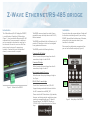
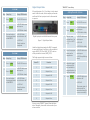
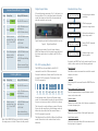
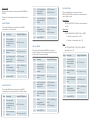
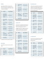
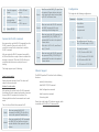
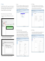
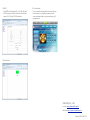
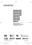
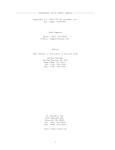
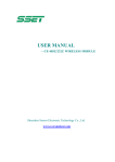
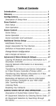
Z-Wave Ethernet/
RS-485 bridge
Technical Specifications
Power
5V-24V, 1A
Signal
908.42Mhz(US),
868.42Mhz(EU)
Range
Up to 100 feet line of sight
between the wireless
controller and the Z-Wave IR
controller station
(282920-200Z).
Serial Port
RS-485
Program
button
To include/exclude the Zwave device.
WARRANTY
Limited One (1) Year Warranty
This warranty does not cover or apply to:
(a) damage to the product due to misuse,
mishandling, and abuse, (b) products not
used in accordance with manufacturer's
instructions or recommendations, (c)
product not assembled or installed
according to manufacturer's instructions, (d)
normal wear and tear, (e) wearing of the
cover do to improper installation of cover
and goods (f) damage to the contents of the
shelter, (g) permits required due to zoning
issues, (h) damage that has occurred during
shipping, (i) acts of God. In addition
consequential damage and incidental
damages, such as damage to persons or
property are not coverable under this
warranty, and you should refer to your
homeowner's insurance policy as with any
other outside structure. Note: Some states
do not allow the exclusion or limitation of
certain damages, and in those cases these
limitations do not apply.
Certification Notice
This device complies with part 15 of the FCC
rules. Operation is subject to the following
two conditions:
● This device may not cause harmful
interference
● This device must accept any
interference that may cause undesired
operation.
Order Information:
HSC-45: Standard version
ST-485Z: Integrated version of intercom
Model:2829-485Z V1.0
Z-Wave Ethernet/RS-485 bridge
Installation
Introduction
The Z-Wave Ethernet/RS-485 bridge(the “BRIDGE”)
is a multi function IO module of Z-Wave device
(Figure 1). It can translate the Ethernet and RS-485
commands into Z-wave commands. In addition, it
can be connected to relay board to control up to
four channels. We can turn on or turn off all four
ports at once by using any Z-wave primary
controller. If we need to control the individual
channel, a scene controller is required.
The BRIDGE can accept input from other Z-wave
compatible sensors and relay them to the RS-485/
Ethernet network.
The BRIDGE has additional built-in Ethernet port. It
provides CGI interface so that it can be integrated
to any products with browser.
The BRIDGE provides the following functions,
Press and release the program button of bridge will
be the device into learning mode. If you are using
REMOTE, please follow the below steps. Otherwise,
please refer to the instruction sheet of your
controller for the details.
Please open the configuration compartment then
you can see the Remote setup keys (Figure 2).
Z-wave to RS-485 bridge
When it receives the input change from other Zwave device, bridge it to the RS-485.
Z-wave to IP bridge
Status
LED A
When it receives the input change from other Zwave device, bridge it to the IP.
Four channel network IO server.
When the status of any input changes, bridge to
the IP port.
RS-485/IP to Z-wave bridge
Control the Z-wave devices from IP/RS-485.
Figure 1 Outlook of the BRIDGE
Status
LED B
Support learning mode which allow us to define
the 485 command to send BASIC_SET.
Please note that all Z-Wave devices, light switches,
dimmers, and shutter switches made from various
vendors are compatible with your “Z-Wave AV
Scenario Remote” (the “REMOTW”, Model no.:
172820-100Z) as long as they carry the Z-Wave
logo:
Figure 2 Setup Keys of the REMOTE
Inclusion
Step
1
Setup Key
Press
Setup LED Behavior
ADD
2
Press DEVICE
The OK LED turns on
“REMOTE” Scene Setup
Digital Output Mode
If the configuration #1 is 1, the bridge is in the output
mode. Under this mode, the four output port become
usable and the four input port must be disconnected
to any wire.
Adding Device to A Scene
Step
1
● OK LED blinks once
and stays on
Press and release
the program button
of the BRIDGE
● OK LED blinks
once then turns off
Exclusion
Step
1
Setup Key
Setup LED Behavior
Press
CLEAR
The OK LED turns on
Press DEVICE
● OK LED blinks once
and stays on
2
● LED B blinks slowly
3
Press and release
the program button
of the BRIDGE
Press
ADD
The OK LED turns on
SCENE
● OK LED blinks once
and stays on
Press
● LED A blinks slowly
Digital Input port must be disconnected to any wire
● LED B off
Device inclusion
completed
Setup LED Behavior
2
● LED B blinks slowly
3
Setup Key
3
Figure 3 Digital Output Mode
Under the digital output mode, the BASIC is mapped
to scene switch binary. It will turn on all ports when it
receive (BASIC_SET,99) or (BASIC_SET,255) and turn
off all ports when it receive (BASIC_SET,0).
Select a scene
number from 1 to
16 (1-8 or SHIFT
1-8)
Function
1
Output #1 off
2
Output #1 on
3
Output #2 off
● OK LED blinks
once then turns off
4
Output #2 on
● LED B off
5
Output #3 off
Device Exclusion
completed
6
Output #3 on
7
Output #4 off
8
Output #4 on
● LED A off
● LED B blinks slowly
4
Press the program
button on the
target device
The Bridge supports eight scenes as below.
Scene ID
● OK LED blinks once
and stays on
5
Adjust the target
device on/off or
dim level with its
program button, to
the desired status
6
Press
SCENE
● OK LED blinks once
and stays on
● LED B keep blinking
slowly
● OK LED blinks once
then turns off
● LED B off
If you are using “REMOTE”, please follow the below
steps. Otherwise, please refer to the manual of your
scene controller.
The current status of
the device will be
learned and saved to
a scene successfully.
Remove Device from A Scene
Step
1
Setup Key
Setup LED Behavior
Press
REMOVE
The OK LED turns on
SCENE
● OK LED blinks once
and stays on
2
Press
Digital Input Mode
Standard Setup Flow
If the configuration parameter #1 is 0, the device is in
the input mode. This is the default mode. Under this
mode, the output port should be disconnected and
only the input port can be used.
Enter Learning Mode
Use the program button
on bridge.
Select Target Device
Click the program
button on target device.
Select Setup Mode
Follow the indication to
select setup mode.
Figure 4 Digital Input Mode
Send RS485 Command
Send a RS485 Command
to bridge.
Under the input mode, if any of inputs changes,
BRIDGE will keep track fo the status change and send
the status report when it is polled by the RS-485 or
Ethernet.
Exit Learning Mode
● LED A blinks slowly
3
Select a scene
number from 1 to
16 (1-8 or SHIFT
1-8)
● OK LED blinks once
and stays on
● LED B blinks slowly
4
Press the program
button on the
target device
● OK LED blinks once
and stays on
● LED B keep blinking
slowly
Device removed from
the scene successfully
Deleting A Scene
Step
1
Setup Key
Press
Press
Setup LED Behavior
CLEAR
The OK LED turns on
SCENE
● OK LED blinks once
and stays on
2
Digital output port must be disconnected to any wire
● LED A off
● LED A blinks slowly
By default, the BRIDGE will in the switch mode. We can
switch to other modes by the following methods.
RS-485 Learning Mode
Switch2 mode
The BRIDGE can be controlled by the RS-485
command to send the Z-Wave commands.
We need to define the Z-wave node ID and the value
for each RS-485 commands. The format of each
RS-485 command is
len cmd
C0
ID
9
27
port
val
Send Multi-instance command to control the second
channel of a device.
IR mode
Send a simple AV command from the REMOTE to the
bridge
RS-485
Command
dev
Sensor mode and Curtain mode
CS
C1
Press the program button to cycle between switch,
sensor and curtain mode.
In the learning mode, all ports will become output
mode. It's recommended to unplug the terminal block
if you are not sure your device is safe to this change.
Capture mode
Local port mode
Scene deleted from
the scene successfully
The (dev,port) is used to define an external UI entity.
We can use the setup flow in the following section to
define the actions which will be executed when a
RS-485 command is received.
Note: If the ERROR LED turns on or blinks, meaning
the setup process is failed. Please redo the process.
The definition of the val field is different for different
mode. Please refer to the sections below for their
definition.
3
Select a scene
number from 1 to
16 (1-8 or SHIFT
1-8)
● OK LED blinks once
and stays on
● LED A off
Reboot bridge to exit
learning mode.
Capture the current status of all devices associated to
a certain (dev,port) pair.
Report the current status of the digital input ports .
Local button mode
Define the command which will be sent when one of
the input port is triggered.
Scene mode
3
Send a scene activation set command from REMOTE to
BRIDGE. Please refer to the latter section for the details of each
mode.
4
Switch Mode
This mode will define a command to send BASIC
command to a Z-Wave device.
Step
1
Setup Key
Press and Hold
program button
for more than 4
seconds
6
Press the program
button on the
target device
● LED 1 stays on
Send a
corresponding
RS-485 command
● LED 1~4 blinking 3
times
LED 1 stays on only
● LED 2 turns on
Step
1
2
This mode will define a command to send BASIC
command to the second channel of a Z-Wave device.
2
Release program
button
SWITCH_MULTILEVEL_SET when val is between 0
and 99
Open,close
● LED 1 stays on
SWITCH_MULTILEVEL_START_LEVEL_CHANGE
● Direction is up when val is 128
Reboot BRIDGE
This mode will enable the BRIDGE to capture the
status of a sensor. These sensort status will be sent
to the RS-485 device periodically.
Switch2 Mode
Press and Hold
program button
for more than 4
seconds
● LED 1~4 blinking 3
times
Set position
Stop
3
1
Send a
corresponding
RS-485 command
This mode will define a command to send
SWITCH_MULTILEVEL command to Z-wave devices. It
can be used to send
● Direction is down when val is 129
● LED 1 stays on
Reboot BRIDGE
Setup Key
● LED blink once
Curtain Mode
Sensor Mode
3
Step
Press and hold the
program button of
bridge.
● LED 2 turns on
LED 1~4 turn on
Release program
button
5
● LED 1 stays on
Setup LED Behavior
2
4
5
Press the program
button on the
target device
4
Setup LED Behavior
5
LED 1~4 turn on
6
LED 1 stays on only
Setup Key
Setup LED Behavior
Press and Hold
program button
for more than 4
seconds
LED 1~4 turn on
Release program
button
LED 1 stays on only
Press the program
button on the
target device
● LED 1 stays on
Press the program
button on bridge
again
● LED blink once
Send a
corresponding
RS-485 command
● LED 1~4 blinking 3
times
Reboot BRIDGE
● LED 2 turns on
SWITCH_MULTILEVEL_STOP_LEVEL_CHANGE
when the val is 130
Step
Setup Key
Setup LED Behavior
Press and Hold
program button
for more than 4
seconds
LED 1~4 turn on
2
Release program
button
LED 1 stays on only
3
Press the program
button on bridge 2
times
● All LED turn off
1
4
5
● LED 1 stays on
Send a
corresponding
RS-485 command
Reboot BRIDGE
● LED 1~4 blinking 3
times
● LED 1 stays on
IR Mode
2
In this mode, we will define a command to send
SIMPLE_AV_SET command to Z-wave devices. We can
use it send control any IR-capable AV devices, such as
TV, stereo, or air conditioner.
Step
1
2
3
4
Setup Key
Press and Hold
program button
for more than 4
seconds
Release program
button
Setup LED Behavior
4
LED 1~4 turn on
5
6
LED 1~3 turns on
Send a
corresponding
RS-485 command
● LED 1~4 blinking 3
times
Capture mode
Send an AV
command from
HSK-100Z(*1)
● LED 1 stays on
In this mode, we can capture the current status for all
devices that are associated with a RS-485 command.
In this way, we can define a scene. After this
procedure, when the RS-485 command is received by
the BRIDGE, it will ignore the val field and then use
the value captured in the capture mode instead.
Send a
corresponding
RS-485 command
● LED 1~4 blinking 3
times
● LED 1 stays on
Step
Setup Key
Press and Hold
program button
for more than 4
seconds
Step
Setup Key
Setup LED Behavior
Press and Hold
program button
for more than 4
seconds
LED 1~4 turn on
2
Release program
button
LED 1 stays on only
3
Press the program
button
LED1 is off and LED2
is on
4
Press the program
of the device.
● LED blinking
1
5
● LED1 is on and
others are off.
Reboot BRIDGE
Setup Key
Setup LED Behavior
Press and Hold
program button
for more than 4
seconds
LED 1~4 turn on
Local input mode
2
Release program
button
LED 1 stays on only
Under this mode, the status of the local port will be
reported to the Ethernet/RS485 by using the
(dev,port) captured.
3
Press the program
button
LED1 is off and LED2
is on
4
Send a
corresponding
RS-485 command
LED1-LED3 will start
blinking until all
states are captured.
5
Reboot BRIDGE
1
Reboot BRIDGE
In this mode, we can clear the commands from the
bridge.
Under this mode, we can define a command which is
triggered by the local digital input port. We can
connect any on/off button to the digital input port so
that we can turn on/off devices according to the
status of the digital input port.
Reboot BRIDGE
● LED 2 turns on
● LED 2 turns off
Local button mode
● LED 1 stays on
● LED 1 stays on
Delete Mode
1
Press and Hold
program button
for more than 4
seconds
Press the program
button on
HSK-200Z
*1 If the dev is 0x35-0x38, the step 4 is optional.
Step
LED 1 stays on only
LED 1 stays on only
● LED 3 turns on
5
3
Release program
button
Setup LED Behavior
Step
Setup Key
Setup LED Behavior
Press and Hold
program button
for more than 4
seconds
LED 1~4 turn on
2
Release program
button
LED 1 stays on only
3
Press the program
button
LED 1 is off and LED2
is on
1
LED 1~4 turn on
4
5
6
Press the program
button
Send a
corresponding
RS-485 command
● LED1-LED3 will
turn on.
Sensor
● LED 1~4 blinking 3
times
● LED 1 stays on
Curtain
Reboot BRIDGE
When we receive the RS-485 command,
the BASIC command will be sent
according to the following table.
When we receive the 485 command, the
captured SIMPLE_AV_CONTROL_SET
command will be sent to the captured
Z-wave device.
Capture the RS-485 command
IR
Now, we need to send the RS-485 command from the
RS-485 controller. Please refer to the RS-485
controller's manual for the instruction to send the
RS-485 command.
We will record the BASIC_SET signal from
the captured Z-wave devices and put it
in the status buffer which can be polled
by RS-485 or Ethernet latter.
Scene
When we receive the RS-485 command,
the captured SCENE_ACTIVATION_SET
command will be sent to the captured
Z-wave devices.
Ethernet Support
Leave learning mode
The BRIDGE provides CGI interface for the following
functions.
Unplug the power and put it back. The device will
return to the normal mode. Include/Exclude devices.
Send BASIC GET/SET command
Send Configuration command
Send Association command
Get routing table
The val is the val field of the command 0x27.
Switch
Switch2
When we received the RS-485
command, the (BASIC_SET,val) will be
sent to the captured Z-wave devices.
When we received the RS-485 command,
the (BASIC_SET,val) will be sent to the
second channel of the captured Z-wave
devices.
Parameter
Description
Device Mode:
0: input mode
1
1: output mode
Default : 0
2
The polling interval. The unit is
10ms. The valid range is 10-255.
The serial port mode.
0: 232/IP mode at 9600 8N1
3
2: 232/IP mode at 115200 8N1
80: 485 mode at 9600 8N1
82: 485 mode at 115200 8N1
The bridge support up to 64 bindings.
After we learn the actions for the RS-485 commands,
the bridge will do the captured action when it receives
the same RS-485 commands in the future. The
following table describes the commands sent in each
mode.
The bridge has the following configuration.
If the dev is 0x35-0x38, we will send
key 6,7,8 and 9.
After we receive the RS-485 command successfully,
all LEDs will blink for a couple of times to indicate the
learning is successful. Then the IO1 LED will stay on
to indicate that the device is ready for the next
binding.
Actions for each mode
Configuration
Please look at the bridge CGI reference manual, which
is available at 2829-485z-CGI-reference.PDF.
IP setup
(1) Login
The BRIDGE will use DHCP to acquire the IP by default.
The Power and ethernet socket are locate at the back
panel of bridge, plug in them and execute the
software (VCOM) to search the IP of bridge.
After you get IP address of bridge, you can enter to
web server to setup the network. The default value
of ID is "admin", and the password is "system".
(3) TCP Mode
You can choose telnet server or Client to set the
server IP address or Port, and set the countdown of
client inactive and server protect timeout.
Please follow the steps to get the IP of bridge:
1. Execute the software (VCOM) and click the search
button.
Click the Search button
(2) Administrator Setting
2. The software will search the bridge in the local
network. And get the IP address of BRIDGE.
3. Use the web interface to configure the BRIDGE.
You can check your kernel version and MAC
address, set the IP setting to DHCP or Static and
change your password setting. The IP is DHCP by
default, and the static IP address is 192.168.2.1,
you can choose static IP and change the IP address.
(4) UDP Mode
You can choose enable the status or disable it, and
set the local port and the remote IP address.
(5) UART
The UART Control provides R-S-232, RS-422 and
RS485 modes, and set the baud rate. The default
value is RS-232 and 115200 baud rate.
(7) User Interface
You can use this friendly web UI to control all your
home systems, e.g. lighting, thermostat, door
access, window shades, security monitoring, A/V
equipment, etc.
(6) Reset Device
SmartTalk Co., Ltd.
E-mail: [email protected]
Web-Site: http://www.smarttalk.com.tw
Model: 2829-485Z V1.0