1
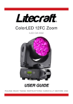
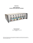
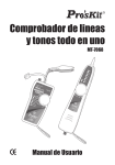
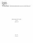
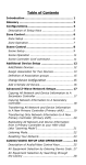
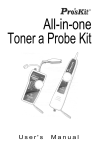
TEGAM
HTRHSERIES
High Temperature, Relative Humidity/
Temperature Probe Transmitter
Publication Date: February 2009
Document Number: HTRH-900-01 Rev D
NOTE: This User's Manual was as current as possible when this
product was manufactured. However, products are
constantly being updated and Improved. To ensure you
have the latest documentation refer to www.tegam.com.
2
TABLE OF CONTENTS
A. GENERAL DESCRIPTION ........ .. ................ .................... 4
B. UNPACKING ................................... ... .............................. 4
C. THEORY OF OPERATION ...................................... ....... 5
D. TERMINAL CONNECTIONS AND TRIM POTS ..... ..... 6
E. WIRING EXAMPLES ....................................................... 7
F. MOUNTING ............................... ............................. .......... 8
G. RH AND TEMPERATURE CALCULATIONS ............... 9
H. RH CALIBRATION ............................ ......................... ... 10
I. TEMPERATURE CALIBRATION .................................. 10
J. MAINTENANCE .............................................................. 11
K. SPECIFICATIONS .......................................................... 12
WARRANTY ....................................................................... 13
STATEMENT OF CALIBRATION ..................................... 13
3
A. GENERAL DESCRIPTION
The stainless steel probe provides relative humidity as well as
temperature out puts. A thin film polymer capacitor senses relative
humidity, while temperature is monitored by a 1000 Ohm platinum
RTD. The sensors are protected by a stainless steel filter cap easily
removed for cleaning. The probe is connected to an electronics
enclosure with a 40 inch (1m) Teflon cable. The enclosure contains
the calibration trimmers, signal and power connections via two
terminal blocks. The probe is available in two configurations, as a
2.5" (64 mm) probe with a wall mounting clip, and as an 8.5" (216
mm) probe with an adjustable duct flange.
B. UNPACKING
Verify that the following parts have been received.
1. Remove probe with cable and electronics enclosure.
2. Instruction manual.
3. Wall mounting clip [for 2.5" (64 mm) probe].
4. 2 piece duct flange, with o-ring, (3) screws, and a gasket.
[for 8.5" (216 mm) probe]
4
c.
THEORY OF OPERATION
A 4 to 20 milliamp loop is a series current loop in which a
transmitter will vary the current flow depending upon the parameter
being ~easured (Relative Humidity or Temperature). Advantages of
a current output over a voltage output is that is less susceptible to
noise interference and allows the connection of more than one meter
or recorder to the loop as long as the maximum resistance is not
exceeded.
The typical current loop will consist of a power supply, transmitter,
and a meter to measure the current flow. The loop resistance is the
sum of the impedance of the meter(s) and the lead wire. The
maximum allowable loop impedance of the probe is found by the
Formula:
Rmax=(power supply voltage-7 volts)/.02 amps
Example: when using a 24 VDC power supply:
Rmax=(24-7)/.02=850 oluns (for total wire length to and
from the transmitter).
A WG WIRE SIZE
RESISTANCE PER 1000 FEET
24
25 OHMS
22
15 OHMS
20
lOOHMS
18
6 OHMS
16
4 OHMS
If the meter or recorder being used accepts only voltage, convert the
current to voltage by installing a 250 ohm resistor across the input
terminals of the recorder to obtain a 1 to 5 volts input.
5
D. TERMINAL CONNECTIONS AND TRIM POTS
TRIMPOTS TYPE
(,-------------:;'\
: rJfJ
1.;1 !;J
I~~~~~I
I
F.l~
I
(8~\8!
,
~
:
l8~ED
I
I
: 1®®®0I0LJ 'LJ V:
A.
B.
C.
D.
E.
RHGAIN
RH ZERO
RH OFFSET
TEMP GAIN
TEMP ZERO
~__________
PROBE TERMINALS
1
2
3
4
5
OUTPUT TERMINALS
1
2
3
4
CABLE WIRE
BLACK
WHITE
GREEN
RED
SHEILD
TYPE
RTD
RTD
RH
RH
TYPE
-RH
+RH
-TEMP
+TEMP
6
E. WIRING EXAMPLES
TYPICAL CURRENT HOOKUP
Wires RI and R2 can be combined into one
single wire with a jumper at pins (4) and (2).
This will result in 3 wires instead of 4.
j
6-30 VOC
POWER SUPPLY
R1
2
I
R2
J
4
RHMETER
ORRECOROER
TEMP. METER
OR RECORDER
7
F. MOUNTING
,....."'"
DUCT
DUCTYAll
I
__
A. DUCT MOUNTING
STEPS
1. Slide flange holder onto probe with countersink
hole facing front of probe as shown.
2. Position a-ring on probe at desired position (for
depth into duct) .
3. Slide duct flange onto probe as shown.
4. Fasten with (3) 6/32 screws and tighten evenly
until secure.
5. Position gasket between duct flange and duct wall
and fasten assembly to duct with (4) #6 sheet
metal screws (not included).
6. Loosening the 6/32 screws allows for
repositioning or removal of the probe without
having to remove the duct flange from the wall.
The duct wall requires a 11116" (.684" or 17.5
rom) hole for probe, with (4) mounting holes
(for #6 sheet metal screws) evenly spaced on a
2.0" (51 mm) circle. Use duct flange as
template.
B. WALL MOUNTING
I. Fasten metal clip to wall.
2. Snap probe into clip.
8
G. RH AND TEMPERATURE CALCULATIONS
I . Maximum current loop impedance for RH or temperature.
Rmax = (V supply - 7 volts) /.02 amps
2. RH current output (i = current output in milliamperes)
3. Temperature current output.
oC = (i-4) x 220/16) - 40 iC = (oC + 40) x (16/220) + 4
of = (i-4) x (396/16) - 40 iF = (oF + 40) x (16/396) + 4
The upper limit of the humidity measurement range decreases based on
temperature. The humidity measurement limit decreases as follows:
2.20% per °C
1.00% per °C
0.50% per °C
0.25% per °C
from
from
from
from
95 to 120°C (1.1 1% per of from 203 to 248°F)
120 to 140°C (0.56% per of from 248 to 284°F)
140 to 160°C (0.28% per of from 284 to 320°F)
160 to 180°C (0.14% per of from 320 to 356°F)
For example, at 120°C the upper humidity limit decreases to about 45%
«120-95)(2.20%) = 55% decrease which is 45%), at 180°C it is reduced
to about 10%.
To calculate the RH accuracy, we'l! use the accuracy specs given in the
specifications section:
+/-2%RH at 25°C and -40° to 150°C at 0.05 % RHloC.
To clarify lets take an example,
RH accuracy at I20°C,
=+/- (2% + (120-25)0.05%) = +/- (2% + 4.75%)
=+/-6.75%
So the accuracy at I20°C is +/-6.75% and the upper humidity
measurement limit is 45% RH.
9
H. RH CALIBRATION
Refer to Section D for the location of trim pots A and B.
Note: The TEGAM RR-CAL Relative Humidity Calibration Kit is
Iecommended for providing the "low" and "high" RR environments for this
procedure. The salt solutions in this kit are prepared according to ASTM
standard EI04-85 to provide 11 .3% and 75.3% relative humidity environments.
The containers provided in the kit are designed to fit with these instruments.
I. Tum the span (trim pot A) all the way up (clockwise).
2. Tum the zero (trim pot B) all the way down (counter-clockwise).
3. Place the sensor in the low (I 1.3%) RR environment. Allow at
least one hour for stabilization or until the output stops changing.
4. Verify the output is 4 +/-.02 rnA. Ifit is not, return the unit to
TEGAM for evaluation and repair.
5. Adjust the zero (trim pot B) to the point where it just starts to cause
a change in the output.
6. Place the sensor in the high (75.3%) RR environment. Allow at
least one hour for stabilization or until the output stops changing.
7. Adjust the span (trim pot A) so the output is equivalent to the
difference between low and high RR environments. Example:
75.3%-11.3% = 64% which is equivalent to 14.24 rnA.
8. Adjust the sensor in the low RH environment and allow at least
one hour for stabilization or until the output stops changing. Verify
the output is equivalent to the low RH environment. Example:
11.3% is equivalent to 5.81 rnA.
I. TEMPERATURE CALIBRATION
Temperature is factory calibrated only, and does not require
any further calibrations.
10
J. MAINTENANCE
If the probe is operated in a dusty environment, the
protective sensor filter, if clogged, may be removed for cleaning.
Unscrew filter and gently blow compressed air through screen.
If necessary, use a soft brush to remove lint from sensors.
If the sensors are subjected to 100% condensation, they must be
dried to obtain correct readings. There is no permanent
calibration shift, nor: is recalibration necessary if 100%
condensation occurs.
The instrument should not be exposed to high
Concentrations of ammonia or alcohol vapors. However,
any environment that is breathable under normal HV AC
applications should not affect the sensors. To maintain original
specifications, it is generally recommended that the RH sensor
be recalibrated on an annual basis depending upon operating
conditions. The temperature sensor does not require calibration.
II
K. SPECIFICATIONS
I.
Relative Humidity: Thin film polymer capacitor.
Input Voltage Range: 7 to 30 VDC (polarity protected).
Range, Accuracy: 3% RH to 95% RH (@-40 to 95°C)*,
±2%RH at 25°C
Typical Temp. Characteristics: -40°C to 150°C at .05%RH/oC
Output: 4 to 20 rna. For O%RH to 100%RH.
Time Constant: Under 30 seconds, 90% response at 25°C in
1M/sec air.
* See RH and Temperature Calculations section for full range.
2.
Temperature: Thin film 1000 ohm platinum RTD.
Input Voltage Range: 7 to 30 VDC (polarity protected).
Range, Accuracy: -40°C to 180°C (-40°F to 356°F), ±0.5°C
(±IOF)
Output: 4 to 20 rna. For -40°C to 180°C (-40°F to 356°F)
Time Constant: Under 4 seconds, 60% response in I mlsec air.
3.
Mechanical
Standard Probe Stainless steel, 2.5" (64 mm) x .625" (16 mm)
diameter. 40" (1 m) Teflon cable, metal wall mounting clip.
Duct Probe: Stainless steel, 8.5" (216 mm) x .625" (16 mm)
diameter. 40" (1 m) Teflon cable.
Duct Flange: 2.75" (70mm) dia., duct hole 11116 (.684",
17.5mm) dia. With 4 mounting holes .156(4mm)
diameter (for #6 sheet metal screws), on 2.00"
(51 mm)circle.
Electronics: Operating temp. -20"C to 70"C( -4"F to 158"F)
ABS housing 4.72" (l20mm) x 3.14" (80 mm) x
2.16" (55 mm) H meets NEMA 1,2,3,4,4X,5,12
and 13 specifications.
Connectors: Liquid-tight with neoprene gland for .09" to .265"
diameter cable.
4-pin plug in screw terminal block for output
connections.
5-pin screw terminal block for cable wire input
connections. Accepts #14 to #22 AWG wires.
Weight:
2.5" (64 mm) probe with housing
14 oz. (397 grams).
8.5" (216 mm) probe with housing and flange
200z. (567 grams).
12
WARRANTY
TEGAM, Inc., warrants this productto be free from defects in material
" and workmanship for a period of one year from date of shipment. During
the warranty period, we will, at our option, either repair or replace any
product that proves to be defective.
To exercise this warranty, write or call TEGAM, Inc. in Geneva, Ohio.
You will be given prompt assistance and return instructions. Send the
i.nstrument, transportation prepaid, to the indicated service facility.
Repairs will be made and the instrument returned, transportation prepaid.
Repaired products are warranted for the balance of the original warranty
period, or at least 90 days.
LIMITATION OF WARRANTY
. This warranty does not apply to defects resulting from unauthorized
modification or misuse of any product or part. This warranty also does
not apply to fuses, batteries, or damage from battery leakage.
This warranty is in lieu of all other warranties, expressed or implied,
including any implied warranty of merchantability or fitness for a
particular use. TEGAM, Inc. shall not be liable for any indirect, special
or consequential damages.
STATEMENT OF CALIBRATION
This instrument has been inspected and tested in accordance with
specifications published by TEGAM, mc.
The accuracy and calibration of this instrument are traceable to the
National Bureau of Standards through equipment which is calibrated at
planned intervals by comparison to certified standards maintained in the
Laboratories ofTEGAM, Inc.
13
14
TEGAM
10 TEGAM WAY . GENEVA, OHIO 44041
PHONE 440-466-6100 . FAX 440-466-6110
www.tegam.com
15