1
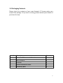
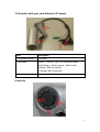
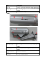
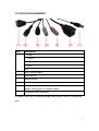
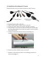
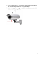
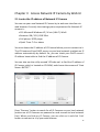
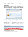
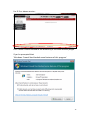
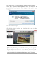
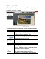
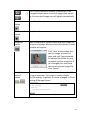
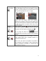
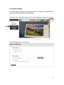
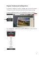
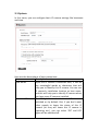
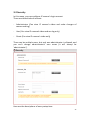
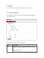
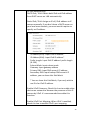
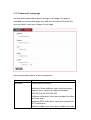
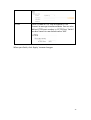
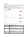
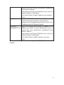
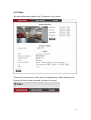
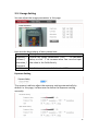
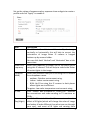
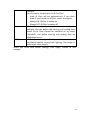
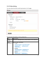
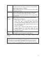
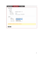
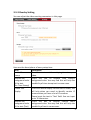
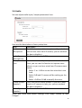
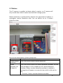
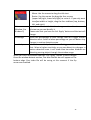
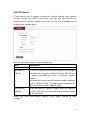
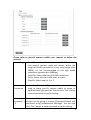
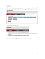
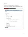
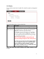
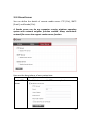
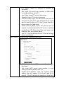
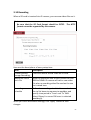
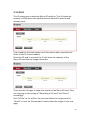
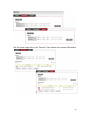
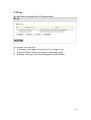
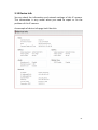
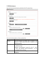
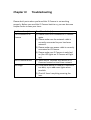
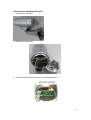
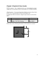
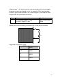
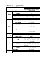
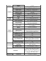
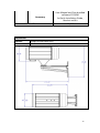
3M IP Camera: Bullet + WDR + PoE
User Manual
Release: 3 April 2014
-
Chapter I
CONTENTS -
Introduction ................................................................................................ 3
1.1 Highlights of your new Network IP Camera..................................................................... 3
1.2 Safety Instructions ........................................................................................................... 4
1.3 Packaging Contents.......................................................................................................... 5
1.4 Familiar with your new Network IP Camera.................................................................... 6
1.5 DI/DO PIN ASSIGNMENT .................................................................................................. 9
1.6 Installation of the Network IP Camera .......................................................................... 10
2.1 Locate the IP address of Network IP Camera ................................................................ 12
2.2 Access to IP Camera’s Web User Interface and Install ActiveX Plugin .......................... 14
2.3 Viewing Live Video......................................................................................................... 17
2.4 Client Settings................................................................................................................ 20
Chapter III Advanced Configuration ................................................................................ 22
3-1 System ........................................................................................................................... 23
3-2 Security.......................................................................................................................... 25
3-3 Network......................................................................................................................... 27
3-3-1 ‘General’ setup page .............................................................................................. 27
3-3-2 ‘Advanced’ setup page........................................................................................... 30
3-4 IP Filter .......................................................................................................................... 33
3-5 Video ............................................................................................................................. 35
3-5-1 Image Setting ......................................................................................................... 36
3-5-2 Video Setting.......................................................................................................... 39
3-5-3 Overlay Setting....................................................................................................... 42
3-6 Audio ............................................................................................................................. 44
3-7 Motion........................................................................................................................... 45
1
3-8 PTZ Control.................................................................................................................... 47
3-9 Event.............................................................................................................................. 49
3-9-1 Settings................................................................................................................... 50
3-9-2 Media ..................................................................................................................... 52
3-9-3 Event Server ........................................................................................................... 53
3-10 Recording .................................................................................................................... 57
3-11 SDHC............................................................................................................................ 58
3-12 Log ............................................................................................................................... 60
3-13 Device Info................................................................................................................... 61
3-14 Maintenance ............................................................................................................... 62
3-15 Language ..................................................................................................................... 63
Chapter IV
Troubleshooting .................................................................................... 64
Chapter V Digital I/O User Guide .................................................................................... 66
Chapter VI
Specification .......................................................................................... 68
2
Chapter I
Introduction
1.1 Highlights of your new Network IP Camera
Congratulates on purchasing this high-resolution 3Mega pixels network
IP Camera! This IP Camera provides 3Mega pixels high-resolution video
quality, with the advanced megapixel lens, you can view images remotely
in more detail than conventional close-circuit cameras.
Other highlights of this network IP Camera include:
Ultra-high resolution 3Mega pixel CMOS image sensor.
Analog video (BNC) output, works with conventional video devices
such as TV Monitors, analog DVRs, etc.
Digital input / output interface lets you connect peripherals such as
external alarm, sensor, etc.
Audio input / output interface, you can listen to voices in remote
place, and speak to person in remote place.
Built-in Micro-SD card slot for local storage, which can act like a
stand-alone DVR.
Two Way audio.
3GPP Mobile Surveillance Supported.
RS-485 communication supported.
ONVIF Compliant.
Support IEEE802.3af Power over Ethernet (PoE) standard.
3
1.2 Safety Instructions
Please follow the safety instructions listed below when you’re using this
Network IP Camera, or you would harm this camera and / or yourself!
Also, the warranty will become void if you disobey these safety
instructions.
This Network IP Camera is sophisticated electronic device; do not
drop it from high places.
Do not place this IP Camera at hot / humid places, and avoid direct
sunlight.
This IP Camera is not a toy; keep it out from the reach of children.
Do not insert any accessories of this IP Camera into your body.
Make sure lens set is secured when you’re using this IP Camera, lens
set may fall down if it’s not properly secured, and cause damage to
human and itself.
If you want to use this IP Camera at any place that may be spilled by
water or dirt, a secure and water-proof camera housing is required.
Do not pull any cord that is connected to this IP Camera by force.
IP Camera will become hot after long time of use. Refrain from touch
IP Camera with hand, or cover this IP camera with paper or cloth.
Never connect powered cable to IP Camera’s DI/DO contacts.
If the IP Camera falls into water when powered, do not attempt to
retrieve it back by yourself! Find a qualified electric technician for
help.
4
1.3 Packaging Contents
Please check the contents of your new Network IP Camera when you
unpack the package. If any item is missing, please contact your dealer of
purchase for help.
Item No. Description
Quantity
1
Network IP Camera with Bracket
1
2
Sun Shield Kit
1
3
CDROM
1
4
Quick Installation Guide
1
5
Accessory pack
1
5
1.4 Familiar with your new Network IP Camera
Item
Description
1. IP camera device
IP camera
2. I/O cable
RS485-+ , DI/DO , GND , DC12Volt/2A input
Reset Button , Audio output , Audio input
Network, RJ45 connector
TV output, BNC connector
3. Bracket
Anti-sheared bracket
[Front site]
6
Item
Description
1. IR-LED
Used for illumination assistance under night mode
2. Day/night sensor
Used for day/night detection and IR-LED ON/OFF
control
3. Lens
[Back]
Vari-focal focal length.
Item
Description
1. Sun Shield Screw
Connects between camera device body & sun
shield.
2. Sun Shield
Protect camera device body from sun shine or rain
directly
3. Camera device
body
IP camera metal case
4. Bracket
The anti-sheared bracket
7
5. Cable Glands
For water proof
6. Zoom/Focus Screw
Screw for zoom/focus adjust
8
1.5 DI/DO PIN ASSIGNMENT
Item
Description
1
- : RS485+ : RS485+
1 : DO
2 : GND
3 DI
2
DC12 Volt/2A input
3
Reset Button
4
Audio output
5
Audio input
6
Network, RJ45 connector, two LED index, orange color is
power index, green is network index
7
TV output, BNC connector
※Please check the I/O cable attached index before insert or release any
wire.
9
1.6 Installation of the Network IP Camera
Please follow the instructions below to setup your new IP camera.
1.
2.
3.
4.
Connect Ethernet cable to LAN port.
Plug DC power adapter to power outlet on the wall.
Connect DC power cable to IP Camera’s DC power connector.
If everything’s ok, you should see the left LED light on LAN port light
up. If not, please recheck every step and try again, or ask your dealer
of purchase for help.
5. Unplug the power then find the screws in the package, use
screwdriver to fix the sun shield on the device’s main body.
6. Secure the bracket of bullet camera on the wall.
7. Repower on the camera and refer to the following procedures to
access and configure it.
10
8. If this IP Bullet camera is connected to a PoE switch then the device
can be powered on without use the power adapter.
9. Adjust the zoom/focus range through the 'zoom/focus screw', which
shows in the following picture.
11
Chapter II Access Network IP Camera by Web UI
2.1 Locate the IP address of Network IP Camera
You can use your new Network IP Camera by its web user interface via
web browser. Currently the viewing system requirement for Network IP
camera is:
˙OS: Microsoft Windows XP / Vista / WIn7 / Win8
˙Browser: IE8 / IE9 / IE10 32bit
˙Cell phone: 3GPP player
˙Quick Time: 7.0 or above
You must know the IP address of IP Camera before you can connect to it.
The IP Camera will use DHCP server on your local network to obtain an IP
address automatically by default. So, you can check your DHCP server’s
IP address lease table to find the IP address of IP Camera.
You can also use the utility named ‘IPFinder.exe’ to find the IP address of
IP Camera, which is located on CD-ROM, and choose the camera of “Host
Name: BU7317”.
Press ‘Discover’ button to search for all IP Cameras on your local network
(make sure all IP Cameras are powered on and connect to local network
first). When you find any IP Camera, you can click on it and click ‘Link’
button to connect to it by your web browser.
12
If you need to change a certain IP Camera’s IP address, you can also click
on the IP Camera you wish to change IP address, then click ‘Change IP’
button to change select IP Camera’s IP address setting.
If you no longer need to use this utility, click ‘Exit’ button to close it.
Please note:
If you have several network connections, such as “Wireless
Function”, please disable the “Wireless Functions” or / and
other network connections that is not connected to IP
camera,, or IP finder may fail to search IP camera!
13
2.2 Access to IP Camera’s Web User Interface and Install
ActiveX Plugin
When you know the IP address of IP Camera, you can connect to it by
Internet Explorer web browser by entering its IP address in address bar.
The use login screen will appear when you get connected:
IP Camera’s administrator username and password are both ‘admin’
(lower case) by default. Click ‘OK’ button or press ‘ENTER’ key on your
keyboard when you finish entering username and password.
When you connect to IP Camera for the first time, you’ll see the
following message. This message prompts you that you need to install
ActiveX plugin before you can see the video from IP Camera.
For IE 8 and earlier version:
Right click the indication bar and click:
‘‘Install This Add-on for All Users on This Computer…’
to install ActiveX plugin.
14
For IE 9 or above version:
Click ‘Install’ button located at the bottom of IE to install ActiveX plugin.
If you’re prompted that:
‘Windows Firewall has blocked some features of this program’
15
Click ‘Allow access’, or IP Camera will not be able to function properly.
When you’re installing Internet Explorer plugin, you may also be
prompted that if you want to allow changes to be made to your
computer:
Click ‘Yes’ to allow changes.
After ActiveX plugin is installed, you should be able to see the video
stream from camera.
NOTE:
If this is the first time you use this IP Camera, you can refer to
chapter 2.4 for instructions on Setup Wizard, which will guide
you to complete the software setup of your new IP Camera.
16
2.3 Viewing Live Video
After ActiveX control is installed, you can view IP camera’s video by web
browser. Just connect to IP camera by web browser and login, then you
can see live video from IP camera:
There are various controls on web page, here are descriptions of every
control item:
Item
Description
‘Home’ button This button is visible in all setup pages of IP camera,
and you can go back to live video view by clicking
this button when you’re in other page.
Stream
Select video stream type: H.264 or MJPEG. H.264
required less network bandwidth and this will help
when network connection is slow.
Digital Output Switch digital output interface on or off.
(ON / OFF)
Client Settings Open ‘Client Setting’ menu.
Configuration
Open ‘Configuration’ menu.
Language
Open language menu, you can switch web interface
to other language.
Available languages: English, Simplified Chinese,
Traditional Chinese and Japanese
Original size /
Switches live image view between original size (full
Fit screen
size: 3M pixels) and fit screen (smaller size).
If you want to see video in detail, switch to original
17
size. If your computer monitor’s resolution is not
/ enough and you want to see full image view, switch
to fit screen and image size will adjust automatically.
‘Connect’
button
Start live video view.
‘Disconnect’
button
Stop live video view.
‘Snapshot’
button
Take a snapshot or camera video and save image file
on your computer. When you click this button, a new
window will appear:
Click ‘Save’ button when you
see the image you wish to
save, and you’ll be prompted
to indicate the folder on your
computer to save image file. If
you changed your mind and
don’t want to save image file,
click ‘Cancel’.
‘Start Video
Record’
button
Click this button to record video and save video file
on your computer. The image is saved in folder
‘C://Recording’ in default. It can be changed in Client
SettingStorage Option.
18
‘Enable Digital
Zoom’ button
Enable /
Disable mute
button
This function will enlarge video view digitally from
1X to 10X. Move the bar up to see objects in screen
in detail. The blue square in the small screen at the
left top side high lights the zoom in range.
Please note: that digital zoom uses computer
algorithm to enlarge the video and some details may
lost. If you need to focus on detail of specific objects
in video view, please use optical zoom ring on lens
set of IP camera.
When mute is enabled ( ), you will not hear the
voice from IP camera; If you want to hear voice from
IP camera, click this button to disable mute ( ).
/
You can drag the slide bar (
) beside
enable/disable mute button to adjust audio playback
volume.
Start / Stop talk Start or stop playing your voice through IP camera’s
Button
audio output. When talk is stopped, people at IP
camera will not hear you.
/
Please note: you need a microphone connected to
your computer, and computer’s mixer setting must
enable microphone recording, or nothing will be
outputted by IP camera.
19
2.4 Client Settings
In ‘Client Settings’ menu, you configure basic IP camera settings like data
transfer protocol and data storage folder.
To access ‘Client Settings’ menu, click ‘Client Settings’ button on the left.
The following screen will appear:
20
Here are the descriptions of every setup item:
Item
Description
RTSP/RTP over TCP
Select this option to use RTSP (Real-Time
Streaming Protocol) to transfer video data over
TCP.
RTSP/RTP over UDP
Select this option to use RTSP (Real-Time
Streaming Protocol) to transfer video data over
UDP.
HTTP
Select this option to use HTTP (Hyper-Text
Transfer Protocol) to transfer video data.
If you don’t know which one you should use,
select ‘RTSP/RTP over TCP’.
Folder
Select a folder on your computer to save
recorded video. Click ‘Browse’ button and
you’ll be prompted to select a folder.
Prefix
When saving video files, the characters you
typed in ‘Prefix’ field will be used as leading
characters of video file’s name.
For example, the default setting of ‘Prefix’ is
‘CLIP’, and video file’s named will be ‘CLIPxxxx’,
where xxxx is a 4-digit serial number.
Add date and time
Check this box to add data and time to the
suffix to file name
ending part of video file’s filename, so you can
see the date and time the video file is created
directly from its filename.
When you finish with above settings, click ‘Apply’ button to save
changes.
21
Chapter III Advanced Configuration
If you wish to configure IP camera’s settings, you can access IP camera’s
‘Configuration’ menu, which provides various kinds of system setting.
To access configuration menu, click ‘Configuration’ button on the left.
The ‘Configuration’ submenu will appear, please pick a setup item you
wish to configure.
22
3-1 System
In this menu, you can configure basic IP camera settings like hostname
and time.
Here are the descriptions of every setup item:
Item
Description
Host Name
Input the IP camera’s hostname here, it can be
any meaningful words or characters that will
help you to identify this IP camera. You can use
IP camera’s installation location as host name,
and this will help you to identify IP camera when
you have many IP cameras installed.
Indicator LED
The LED lights located at the back of IP camera is
switched on by default. But, if you don’t want
other people to know the status of this IP
camera (so they will know this IP camera is
operating etc.), you can select ‘Off’ and LED
lights will be switched off.
23
TimeZone
Daylight Saving
Keep the current
date and time
Synchronize with
computer time
Synchronize with
NTP Server
Select the time zone of residence from
dropdown menu to keep correct date and time.
If the area you live uses daylight saving, check
this box; otherwise do not check this box to keep
time correct.
Select this option and date / time setting will not
be changed when you click ‘Apply’ in the page.
You can check ‘Camera Date and Time’ item in
this page to know IP camera’s current date and
time setting.
Select this item and IP camera will use your
computer’s time as its time.
Select this item and IP camera will keep its date
and time setting synchronized with specified
time server (NTP server). Please input NTP
server’s IP address or host name in ‘NTP Server
Address’ field, and select time update interval
from ‘Update Interval’ dropdown menu.
Please note that if this IP camera can’t access
Internet, you must have a time server on local
area network, or set the time manually.
Set Manually
Set IP camera’s date and time manually. Please
set current date and time by ‘Date’ and ‘Time’
dropdown menu.
When you finish with above settings, click ‘Apply’ button to save
changes.
24
3-2 Security
In this menu, you can configure IP camera’s login account.
There are three kinds of account:
- Administrator (Can view IP camera’s video and make changes of
camera setting)
- User (Can view IP camera’s video and see log only)
- Guest (Can view IP camera’s video only)
There can be multiple users, but only one administrator is allowed, and
you can’t change administrator’s user name (it will always be
‘administrator’).
Here are the descriptions of every setup item:
25
Item
Password / Retype
Password
(Administrator)
Account List
User Name
Password / Retype
Password
Authority
Description
Input administrator’s new password in both
‘Password’ and ‘Retype Password’ field, and
click ‘Modify’ button to change administrator’s
password.
Please note: Don’t forget administrator’s
password! Or you’ll need to reset IP camera’s all
settings to get administrator’s password
recovered.
Here lists all users existed in IP camera. If you
want to remove one user, click it in the list, and
then click ‘Remove’ button.
If no user is existed, ‘New Account’ message will
be shown here.
Input new user’s username here. User name
must be greater than 1 character and less than
32 characters.
Input this user’s password in both ‘Password’
and ‘Retype Password’ field.
To define this user’s access privilege, select
‘User’ or ‘Guest’ in dropdown menu.
When you finish inputting new user’s
information, click ‘New’ button to create a new
user.
26
3-3 Network
In this menu, you can configure IP camera’s network setting.
3-3-1 ‘General’ setup page
Setup IP address for this IP camera. This IP camera supports both IPv4
and IPv6 IP address.
Here are the descriptions of every setup item:
Item
LAN
Description
Select this option to assign an IP address to LAN port
(or obtain an address from DHCP server automatically).
Available options are:
DHCP IPv4: Obtain an IPv4 IP address from DHCP server
27
on LAN automatically.
DHCP IPv4 / IPv6: Obtain both IPv4 and IPv6 address
from DHCP server on LAN automatically.
Static IPv4 / IPv6: Assign an IPv4 / IPv6 address to IP
camera manually. If you don’t have a DHCP server on
your local area network, you must use this option to
specify an IP address.
IP Address(IPv4): Input IPv4 IP address*
IP Address(IPv6): Input IPv6 IP address*
Prefix Length: Input IPv6 IP address’ prefix length
(0-128)
Subnet Mask: Input subnet mask
Gateway: Input gateway address
Primary DNS: Input DNS server’s IP address
Secondary DNS: Input backup DNS server’s IP
address, you can leave this field blank.
* You can leave this field blank, if you only wish to
use IPv4 or IPv6 IP address.
Enable UPnP Discovery: Check this b ox to enable other
devices on network to discover the presence of this IP
camera by UPnP. It’s recommended to enable this
function.
Enable UPnP Port Mapping: When UPnP is enabled,
check this box to enable UPnP’s port mapping.
28
PPPoE
HTTP Port
Select this option to use PPPoE to connect to network.
You have to input PPPoE username and password
assigned by network operator to get connected.
Input IP camera’s web connection port number here.
When this port number is changed, you need to change
web browser’s port number you used to connect to IP
camera.
RTSP Port
For example, IP camera’s IP address is 192.168.2.3, and
if you changed HTTP port number to 82, please input
‘http://192.168.2.3:82’ in web browser’s address bar to
access IP camera’s web configuration interface.
Input RTSP port number. When this port number
changes, you must change corresponding settings in
external network devices (NVR or CMS software) so
they can receive this IP camera’s video.
Input RTP data port number here.
RTP Data
Port
When you finish with above settings, click ‘Apply’ button to save
changes.
29
3-3-2 ‘Advanced’ setup page
You can setup advanced network settings in this page. This page is
intended for advanced settings only, and this IP camera will work fine
even you don’t make any changes to this page.
Here are the descriptions of every setup item:
Item
Multicast
Description
Enable video multicast:
Multicast Group Address: Input multicast group
address here, must be an address between
232.0.0.0 to 232.255.255.255.
Multicast video port: Input port number for video
multicast here.
Multicast RCTP video port: Input port number for
RCTP video here.
Multicast audio port: Input port number for audio
30
here.
Multicast RCTP audio port: Input port number for
RCTP audio here.
Multicast TTL: Input TTL value for multicast here.
Bonjour
QoS
If you’re using Mac OS and you have Bonjour
installed, you can use it to discover this IP camera.
Enable QoS to improve the data transfer priority
of this IP camera (Your local area network must
support QoS).
You can select Video / Audio’s QoS DSCP value (0
to 63), or both video and audio.
DDNS
Enable DDNS support if your ISP assigns dynamic
IP address to you. You must register a dynamic IP
service first. Currently this IP camera supports
DynDNS, TZO and No-ip dynamic IP service.
Provider: Select dynamic IP service provider.
Host Name: Input the host name you obtained
from dynamic IP service provider.
User name: Input user name used to login
dynamic IP service provider.
Password: Input the password used to login
dynamic IP service provider.
31
HTTPS
Check ‘Enable HTTPS’ box to enable HTTPS
channel to encrypt transferred data. You can also
define HTTPS port number in ‘HTTPS Port’ field if
you don’t want to use default value ‘443’.
When you finish, click ‘Apply’ to save changes.
32
3-4 IP Filter
When this IP camera is directly connected to Internet and not protected
by firewall, this function acts like a mini built-in firewall to protect the
safety of this IP camera and avoid attacks from hackers.
Here are the descriptions of every setup item:
Item
Description
Enable Filter
Check this box to enable IP address filter, uncheck
this
Box to disable this function.
Accepted IP list Here lists all IP address that can build connections
to this IP camera. If you want to remove a set of IP
address from the list, click on the IP address and
click ‘Remove’ button.
IP Address
Input the starting and ending IP address of IP
(Accepted IP list) address you wish to accept connections here. IP
33
camera will only accept connections established
from these IP address.
If you want to specify one IP address only, input the
same IP address in both field.
Click ‘New’ button to add IP address into accepted
IP list.
Deny IP list
Here lists all IP address that cannot build
connections to this IP camera. If you want to
remove a set of IP address from the list, click on the
IP address and click ‘Remove’ button.
IP Address
Input the starting and ending IP address of IP
(Accepted IP list) address you wish to deny connections here. IP
camera will deny connections established from
these IP address.
If you want to specify one IP address only, input the
same IP address in both field.
Click ‘New’ button to add IP address into deny
IP list.
When you finish with above settings, click ‘Apply’ button to save
changes.
34
3-5 Video
You can adjust the image of the IP camera in this menu.
There are 3 sub-menus in this menu: Image Setting, Video Setting, and
Overlay, which can be accessed by tabs on the top:
35
3-5-1 Image Setting
You can adjust the image parameters in this page.
Here are the descriptions of every setup item:
Item
Description
Brightness / Control the image parameters. Click ‘ - ' to decrease
Contrast /
value, or click ‘ + ‘ to increase value. You can also input
Saturation / the value in the field directly.
Sharpness
Default
Set all above values to default value ‘128’.
Exposure Setting
This camera is able to adjust the exposure setting automatically by
default. In this page, it allows user to define the exposure setting
manually.
36
Set up the values of exposure value, exposure time and gain to create a
profile and click “Apply” to enable it.
Item
Mirror
Power Line
Frequency
Condition
(AWB)
TV Out
IR-cut
(Day/Night)
Description
Check ‘Vertical’ or ‘Horizontal’ box to flip the image
vertically or horizontally, this will help to correct the
orientation of image when IP camera is hanged
bottom-up by camera holder.
You can click both ‘Vertical’ and ‘Horizontal’ box at the
same time.
Select the frequency of power line of the place you’re
using this IP camera. This will help to reduce the flicker
of certain lights in the image.
Select the condition that you’ll be using this IP camera
from dropdown menu.
- outdoor: Outdoor environment using.
- indoor: Indoor environment using.
- B/W: You’ll be using this IP camera in dark places
where lights are insufficient.
Tungsten: Low color temperature environment using.
Click “Enable” box to enable its “VIDEO OUT” function
for connections and video sending to TV monitors or
DVRs.
An IR-Cut filter is built in this IP camera to reduce the
effect of IR lights (which will change the color of image
and makes it looks different than what you see through
your eye), and most of IR lights are coming from
37
sunlight.
You can select the behavior or IR-Cut filter:
- Auto: IR filter will act automatically. If you don’t
know if you should use IR filter, select this option.
- Always ON: IR filter is always on.
- Always OFF: IR filter is always off.
Day
IR-Cut filter will only be switched on when there’s
sunlight. You can define the starting and ending time
when IR-Cut filter should be switched on by select
‘Schedule’ and define starting and ending time by
dropdown menu.
WDR
Wide dynamic range: Enable it when the object
positioned against strong back lighting. The image is
able to get more details.
When you finish with above settings, click ‘Apply’ button to save
changes.
38
3-5-2 Video Setting
You can adjust the video transfer parameters in this page.
Here are the descriptions of every setup item:
Item
Description
H.264
Select the compression of main stream: H.264 / MPEG4.
/MPEG4
Video
Select video resolution.
Resolution - H.264:
2048x1536 (QXGA) / 1920x1080 (1080p)
1280x960 (960p) / 1280x720 (720p)
720x480 (D1)
/ 640x480 (VGA)
320x240 (QVGA)
- MPEG4:
1920x1080 (1080p) / 1280x960 (960p)
1280x720 (720p) / 720x480 (D1)
640x480 (VGA) / 320x240 (QVGA)
MJPEG:
1280x720 (720p) / 720x480 (D1)
640x480 (VGA) / 320x240 (QVGA)
39
Please note that some video resolution is not available
when video encoder is ‘MPEG4’.
When network speed is insufficient, select a lower video
resolution will help.
Frame Rate Select video frame rate. Please note that some frame
rate is not available when video encoder is ‘H.264’.
When network speed is insufficient, select a lower frame
rate will help.
Rate
Select video bit rate. You can control bit rate by both
Control
‘Video quality’ and ‘Bitrate’:
- Video quality: There are 5 levels of video quality,
select ‘very high’ to improve video quality but
consumes more network bandwidth, and select ‘very
low’ will decrease video quality and consumes less
network bandwidth.
- Bitrate: Input video’s bit rate directly. It must an
integer between 512 and 6000. Higher bit rate
provides better video quality, but consumes more
network bandwidth.
Mobile
Checking the radio box to enable remote access when
View
you need to remote access via mobile phone.
When you finish with above settings, click ‘Apply’ button to save
changes.
Note:
MJPEG options are only available for portable devices like cell phone.
The resolution is under 1280 x 720 (720P). The UI page will pop up
when the resolution of H.264/MPEG4 is 720P or below like hereunder.
40
41
3-5-3 Overlay Setting
You can adjust the video overlay parameters in this page.
Here are the descriptions of every setup item:
Item
Description
Enable Time
Check this box to enable overlaying time stamp on
Stamp
video.
Remove the
Check this box to remove time stamp’s
background color background color. You may find this will help the
of the text
readability of time stamp text in some cases.
(for Time Stamp)
Enable Text
Check this box to display certain text on video, this
Display
will help when you need to identify certain IP
camera when you have a lot of IP cameras.
Please input the text in ‘Text’ field. You can input
up to 15 characters.
Remove the
Check this box to remove custom text’s
background color background color. You may find this will help the
of the text (Text) readability of text in some cases.
42
Enable Image
Overlay
Check this box to overlay a specific image on
video, so you can show certain text / picture on
the video and help people to identify this IP
camera.
Click ‘Browse’ button to pick a picture on your
computer, then click ‘Update’ button to use the
picture. Please note that there are certain
restrictions:
- Select .bmp / .jpg / .jpeg image files only.
- Image’s resolution should be less than 160 x
128, and can be divided by 4.
- Do not upload image files that size is greater
than 64KB.
When you finish with above settings, click ‘Apply’ button to save
changes.
43
3-6 Audio
You can adjust audio input / output parameters here.
Here are the descriptions of every setup item:
Item
Description
Enable
Check this box to enable microphone. If you don’t
Microphone
want to hear voice from IP camera, you can uncheck
this box to disable it.
Audio Type
The format is fixed as G.711
(Microphone)
Microphone
If the voice received by microphone is too loud or
Gain
silent, you can use this function to improve voice
volume, so you can hear voice from IP camera more
clearly.
- Select -2 or -1 dB to correct the voice that is too
loud;
- Select 0 dB and IP camera will do nothing on the
voice;
- Select +2 dB to +26 dB to amplify the voice.
Enable Speaker Check this box to enable speaker. If you don’t want
(Speaker)
people at IP camera to hear you, you can uncheck
this box to disable it.
Audio Type
The format is fixed as G.711
(Speaker)
When you finish with above settings, click ‘Apply’ button to save
changes.
44
3-7 Motion
This IP camera is capable to detect object’s motion, so IP camera will
only record when there’s motion and save disk storage space.
Motion detection is performed by examine the movement of objects in
rectangular motion detection area. You can define up to 3 motion
detection areas.
Here are the descriptions of every setup item:
Item
Description
Enable Motion Check this box to enable motion detection.
Detection
Enable
Check this box to enable this motion detection window. You can
(Window 1 to
select window 1 to 3 to enable up to 3 motion detection
Window 3)
windows. When a motion detection window is enabled, a
rectangular will appear on camera’s view, with its title on the
top.
- To move / resize a motion detection window:
45
- Move: Use the mouse to drag the title text.
- Resize: Use the mouse the drag the four corners
(upper-left/right, lower-left/right) to resize it. If you only want
to adjust width or height, drag the four sidebars (top, bottom,
left, and right).
Title
Input characters in title field to change motion detection area’s
(Window 1 to
title text so you can identify it.
Window 3)
Please note that you have to click ‘Apply’ button and the text will
change.
Percentage
Select the percentage of pixel change that will trigger motion
detection alert. Select a lower percentage so you can detect tiny
changes in motion detection area.
Sensitivity
Select the sensitivity level that will trigger motion detection
alert. Select a higher sensitivity so you can detect tiny changes in
motion detection area. It will show blue bar when window are
detecting moving object through the window range.
When you finish with above settings, click ‘Apply’ button to save changes.
Once the window detects motion, one blue flexible bar will appear at the
bottom edge. One video file will be saving at this moment if the ftp
server was enabled.
46
3-8 PTZ Control
If you mount the IP camera on pan-tilt camera cradles that support
pan-tilt control via RS-485 connection, you can use this function to
control pan-tilt camera cradle so you can control the orientation of IP
camera from remote place.
Here are the descriptions of every setup item:
Item
Description
Enable RS-485 Check this box to enable RS-485 functionality.
Use Pelco-D
Select this option and RS-485 interface will output
Address
pan-tile control signal in Pelco-D format. This format
is widely accepted by most of pan-tilt camera
cradles.
You have also input pan-tilt camera cradle’s address
code in ‘Address’ field. This code must be identical to
pan-tilt camera cradle’s address code.
Use Custom
When the pan-tilt camera cradle does not support
Protocol
Pelco-D protocol, you can define a protocol’s detail
by this function.
When you finish with above settings, click ‘Apply’ button to save
changes.
47
Please refer to pan-tilt camera cradle’s user manual to define the
protocol.
Port Setting - Baud Rate: Select data baud rate of RS-485 interface
that pan-tilt camera cradle will accept. When the
length of RS-485 connection is very long (longer than
200M), it’s not recommended to use high speed
connection (greater than 2400bps).
- Data Bits: Select data bits of RS-485 connection.
- Parity: Select parity bit: odd, even, or space.
- Stop Bit: Select stop bit: 1 or 2.
Customer
Commands
- Home/Up/Down/Left/Right: Input the command string
used to move pan-tilt camera cradle to home or
up/down/left/right position. You can click ‘Test’ button
to send command string for testing.
Extended
You can define extra pan-tilt camera cradle control
Command 1 strings here by giving it a name (Command Name) and
~5
command string (Hexadecimal Message). You can also
click ‘Test’ button to send command string for testing.
48
3-9 Event
When there’s an event, you can use this setup page to define what IP
camera should do, like send an Email or trigger digital output to activate
external alarm.
There are three setup pages:
1. Setting: Define a new event and manage events.
2. Media: Define what kind of media file should be saved on designate
media.
3. Event Server: Define the details of remote server.
Please refer to following chapters for detailed instructions.
49
3-9-1 Settings
This page lists all existing events. You can click ‘Modify’ button to edit an
existing event, or ‘Remove’ to delete an existing event.
To create a new even, just click “New” button to add an Event setting.
50
To add a new event, click ‘New’ button and the descriptions of every
setup item is listed below:
Item
Description
Enable Setting Check this box to enable this event. If you just want
to disable this event temporarily, you can uncheck
this box to keep this event and disabling while not
deleting it.
Title
Input any description text for this event so you can
identify it quickly. You can use alphabets, numbers,
and symbols include: !$-.@^_~ (no spaces allowed).
Motion
Check this box and this event will be activated when
Detection
one of motion detection window detects motion.
Digital Input 1 Check this box and this event will be activated when
“Digital Input 1” input signal is high or low (select
from dropdown list).
Enable
Check this box and this event will be activated when
Schedule Time designated weekday and time is reached.
You also have to check weekday box, and select time
from dropdown list. If you select ‘Always’ as time,
this event will be activated during all the day.
Enable FTP
Check this box and IP camera will save file on FTP
server (refer to ‘FTP Server’ setting in ‘Event Server’
tab) when this event is activated.
Enable EMAIL
Check this box and IP camera will send an Email to
designated recipient address (refer to ‘SMTP Server’
setting in ‘Event Server’ tab) when this event is
activated.
Enable Samba Check this box and IP camera will save file on samba
(Net Storage)
server (refer to ‘Samba Server’ setting in ‘Event
Server’ tab) when this event is activated.
Enable SD
Check this box and IP camera will save file on SD
CARD
card when this event is activated. A working SD card
must be inserted into IP camera in advance.
Trigger digital
Check this box and IP camera will trigger digital out
output for xx
to ‘high’ state for xx seconds when this event is
second(s).
activated, where ‘xx’ seconds must be defined by the
dropdown list.
51
3-9-2 Media
You can define what kind of media file should be saved on designated
media.
Here are the descriptions of every setup item:
Item
Description
One Snapshot Save a picture file when event is triggered.
Maximum
Save a video clip. You can also select the recording
Video File Size length before and / or after the time when event is
triggered in ‘Pre Event’ and ‘Post’ Event’.
For example, if you set ‘Pre Event’ to ‘5’ and ‘Post
Event’ to 5’, and an event is triggered at 14:10:30,
then the video file will be 10 seconds long, starting
from 14:10:25 to 14:10:35.
Notes: The video resolution, image quality and
frame rate setting will affect to max. video file size.
Tips: You may want to know what happened before
event is triggered in many cases, especially when
object is outside of motion detection window.
Note: If the “Pre Event” set to “0” second, the “Post
Event” cannot set to “0” second.
When you finish with above settings, click ‘Apply’ button to save
changes.
52
3-9-3 Event Server
You can define the details of remote media server: FTP (File), SMTP
(Email), and Samba (File).
A Samba server can be any computer running windows operating
system with network neighbor function enabled. Many stand-alone
network file server also support samba server function.
Here are the descriptions of every setup item:
Item
Description
Enable FTP
Check this box to enable FTP server upload.
Server
53
SMTP Server
- FTP Server: Input FTP server’s IP address or
hostname.
- Port: Input FTP server’s port number. In most cases
it should be default value ‘21’.
- User Name: Input FTP server’s username.
- Password: Input FTP server’s password.
- File Path Name: Input the path where you want to
save file on FTP server, like ‘upload/record’. If you
want to save file on this FTP user’s home directory,
you can leave this field blank.
- Enable Passive Mode: Check this box to force IP
camera to communicate with FTP server in passive
mode (Some FTP Server may only work when you
check this box, while others don’t).
- Test FTP: Click this button to test FTP server settings
above immediately.
Check this box to enable Email send.
- SMTP Server: Input SMTP server’s IP address or
hostname.
- Port: Input SMTP server’s port number. In most
cases it should be default value ‘25’.
- Sender Email Address: Input the sender’s email
address that will appear in the Email send by IP
camera. This will help you to identify the Email sent
54
by this IP camera, and may help when you have
anti-spam software installed (you can set this Email
address to ‘White List’ in your anti-spam software)
- Receiver #1 Email Address: Input primary recipient’s
Email address. This field is required.
- Receiver #2 Email Address: Input backup recipient’s
Email address. This field is optional.
- Subject: Input Email title that will appear in the
Email send by IP camera. This will help you to
identify the Email sent by this IP camera.
- Authentication: Check this box when authentication
is required by the Email server you’re using. You also
need to input Email server’s username and
password in corresponding field.
- Requires SSL Encryption: If your Email server
required SSL encryption, check this box. Please note
that some Email server uses different port number
than standard port 25 when SSL encryption is used.
- STARTTLS: If your Email server required STARTTLS
encryption, check this box. Please note that some
Email server uses different port number than
standard port 25 when STARTTLS encryption is used.
- Test SMTP: Click this button to test SMTP server
settings above immediately.
Samba Server Check this box to enable Samba server file upload.
- Samba Server Address: Input Samba server’s IP
address or hostname.
- Path: Input the path where you want to save file on
Samba server, like ‘upload/record’. If you want to
save file on this user’s home directory, you can leave
55
this field blank.
- User Name: Input Samba server’s username.
- Password: Input Samba server’s password.
- Test SMB: Click this button to test Samba server
settings above immediately.
Tips: Some samba server does not have username and
password check, you can just input samba server
address and path to access the file storage space.
When you finish with above settings, click ‘Apply’ button to save
changes.
56
3-10 Recording
When a SD card is inserted into IP camera, you can save video files on it.
Note:
Be sure that the SD Card format should be FAT32. The NTFS
format cannot be supported by this camera.
Here are the descriptions of every setup item:
Item
Description
Enable External
Check this box to record video on SD card.
storage Recording
Maximum Size of
Input the maximum size of every video file from
Each File
1MB to 50MB. IP camera will start a new video
file when a recording video file reaches the size
limit stated here.
Recording
Define the recording schedule. You can check
Schedule
Sun to Sat boxes to represent a weekday, and
specify time period in ‘From’ and ‘To’ field.
Select ‘Always’ to record 24 hours in selected
weekday(s).
When you finish with above settings, click ‘Apply’ button to save
changes.
57
3-11 SDHC
The IP camera has an optional Micro-SD card slot. The UI shows the
capacity is 0 MB when the module without Micro-SD card slot and
memory card.
If you need the function please check the option when you place the
order of the IP camera module.
Once the SD card is inserted, the UI will show the capacity of the
Micro-SD card like the image hereunder.
There are two UI pages to show the record on the Micro-SD card. They
are mapping to the setting of “Recording to SD card” and “Event”
accordingly.
Click “All file” to list all files. You also can define the range and click
“Search” to sort the files needed. It shows likes the images in the next
page.
58
Set the time range then click “Search” then shows the records like below.
59
3-12 Log
You can check the usage log of IP camera here.
In this page, you can click:
1. First page / Final page: Jump to first / final page of log.
2. Previous / Next: Jump to previous or next page of log.
3. Remove: Clear log. You’ll be prompted for confirmation.
60
3-13 Device Info
You can check the information and network settings of this IP camera.
This information is very useful when you need to repair or fix the
problem of this IP camera.
An example of device info page look likes this:
61
3-14 Maintenance
You can do some maintenance job about this IP camera here.
Here are the descriptions of every setup item:
Item
Description
Reboot
Click this button to reboot the IP camera. This
function is useful when you find IP camera is not
working properly.
Factory Reset
(1) Clear all settings of IP camera and reset to factory
default setting.
(2) Reset all parameters, except for the IP , time
zone, and daylight saving parameters , to the
original factory settings
Backup
Backup IP camera’s setting and save it on your
computer.
62
Backup to SD
card device
Restore
Restore from
SD card device
Upgrade
Backup IP camera’s setting and save it on SD card. A
SD card must be inserted into SD card slot when you
click this button, or you’ll receive an error message.
Restore a previously-saved configuration file saved
on your computer. Click ‘Browse’ button to select a
file on your computer first, then click ‘Restore’
button.
Restore IP camera’s configuration which is
previously-saved on SD card.
Upgrade IP camera’s firmware. Click ‘Browse’ button
to select a firmware image file on your computer
first, then click ‘Upgrade’ button.
3-15 Language
You can change the display language of web interface.
Click ‘Language’ button and select one language. More languages may
available in latest firmware file.
63
Chapter IV
Troubleshooting
Please don’t panic when you found this IP Camera is not working
properly. Before you send this IP Camera back to us, you can do some
simple checks to save your time:
Problem description
Can’t connect to IP
Camera
No IP Camera found
No image
Possible solution(s)
1) Please check the IP address of IP Camera
again.
2) Please make sure the network cable is
correctly connected to your local area
network.
3) Please make sure power cable is correctly
connected to IP Camera.
4) Please make sure IP Camera is switched
on (the LED lights on IP Camera will light
up).
1) ‘Auto search’ function only works on IP
Cameras located on local area network.
1) If the place where IP camera is installed is
too dark, try to add some lights when
possible.
2) Check if there’s anything covering the
lens.
64
How to insert the Micro-SD card?
1. remove the sun shield
2. Remove the back cover
3. The Micro-SD Card slot is shown in the following picture.
65
Chapter V Digital I/O User Guide
DI/DO connector – Use in applications for e.g. motion detection, event
triggering, SD recording and alarm notifications via FTP/EMAIL/SAMBA.
•Digital output — For connecting external devices such as relays, alarm
bell or LEDs. Connected devices can be activated by the
ConfigurationEvent interface or digital output buttons on the Home
page.
Pin
Notes
Trigger is “Off”, DO connect to GND
Trigger is “On”, DO is floating
Specifications
Max load:
30mA,30VDC
Please refer to the following illustration for DO connection method
66
•Digital input — An alarm input for connecting devices that can toggle
between an open and closed circuit, for example: PIRs, door/window
contacts, glass break detectors, etc. When a signal is received the state
changes and the input becomes active.
Pin
Notes
DI is floating, trigger is “high”
DI is high, trigger is “low”
Specifications
Max current input:
30mA
Please refer to the following illustration for DI connection method
Suggested Component Value
Power(VDC)
3.3V
5V
12V
RL(Ω)
100Ω
200Ω
510Ω
67
Chapter VI
Specification
Model No.
Description
Image
Sensor
Max. Resolution
Format
Effective Pixels
Pixel size
Active Image Area
Max Dynamic range
Built-in Lens
Lens Mount
Focal Length
F No.
Auto-IRIS
Lens
BU7317
3MP Outdoor H.264 Day / Night IP
Bullet Camera
2048H x 1536V
1/3"
2048H x 1536V
2.2 x 2.2μm
4.51mm(H) x 3.38mm(V)
Up to 100 dB
Yes
Board
3~10.5mm
F1.4~2.0
Yes
H: 91.2°~25.5°
Angle of View
V: 68.4°~19.1°
D: 114°~31.9°
Day/Night
Mechanical IRCF
IR Distance
IR Wave Length
H.264
Video Codec
MPEG4
MJPEG
Codec
Quality
Audio Codec
H.264
MPEG4
Yes, on sensor board
50M/f=10.5mm, AGC on
850nm
20fps @ 2048 x 1536
30fps @ 1920 x 1080 ; 1280 x 960 ;
1280 x 720 ; 720 x 480 ; 640 x 480 ;
320 x 240
30fps @ 1920 x 1080 ; 1280 x 960 ;
1280 x 720 ; 720 x 480 ; 640 x 480 ;
320 x 240
30fps @1280x720 ; 720x480 ;
640x480 ; 320x240
G.711 μ-law
5 Levels or Bit Rate
5 Levels
68
Options
MJPEG
Local Storage
Video out
Alarm in/out
Network
Audio In / Out
LED Indicators
RS-485
Reset
PoE
AC-DC Power
Motion Detection
Mechanical
Dimensions
5 Levels
Micro SD slot x 1 , SDHC
NTSC/PAL, BNC x 1
Alarm in x 1 / Alarm out x 1
10BaseT/100BaseT (RJ45, Female)
Interface
Two-way
Power & Ethernet (1/1)
x1
Yes
Power
Yes, IEEE802.3af compliant
Supply
DC 12V
Yes, 3 scalable windows
Brightness, Contrast, Sharpness,
Image Settings
Saturation Adjustable
5 sec. pre-alarm / 5 sec. post-alarm,
Alarm Buffer
up to 3MByte
Mirror
Vertical / Horizontal
ONVIF
Yes
3.5x optical zoom
Optical zoom
Special
External adjust zoom/focus
Features
Digital Zoom
Yes, up to 10x
Remote Pan / Tilt
Yes
3GPP Supported
Yes
Packet Management
IP Filter ; QoS
Manual Time Setting, Time Server &
Time Management
NTP Support, Real Time Clock
Multi-level User Access
Yes
Multiple Streaming
Yes
o
o
Operating Temp. /
-40 C ~ 50 C (-40oF ~ 122oF) ,
Humidity
20% ~ 85% RH
Environment
Storage Temp.
-20°C~60°C (-4oF ~ 140oF)
Weather Proof
IP66
TCP/IP, IPv4, IPv6, UDP, ICMP,
DHCP, NTP, DNS, DDNS, SMTP, FTP,
Protocols
HTTP, HTTPs, Samba, PPPoE, UPnP,
Bonjour, RTP, RTSP, RTCP
ø 73mm x L 183mm
69
Accessory
Certificate
User Manual and Free bundled
software CD ROM
1 x Quick Installation Guide ,
Bracket and Kit
CE,FCC
Physical Info.
WEIGHT
1330gm (Camera body only)
DIMENSIONS
φ73.0mm x 233.5mm (L)
70