1
Chapter 2
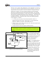
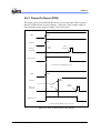
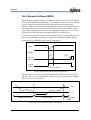
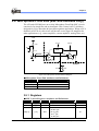
Brown-Out Reset: The MCU is reset when the supply voltage VCC is
below the Brown-out Reset threshold (VBOR).
During reset, all I/O Registers are reset to their initial values, and the program
starts execution from Address 0x0000. The instruction placed at Address
0x0000 must be a Long JMP instruction to the reset handling routine. If the
program never enables an interrupt source, the interrupt vectors are not used,
and regular program code can be placed at these locations.
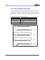
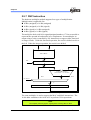
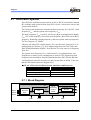
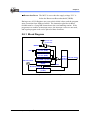
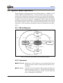
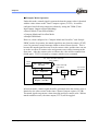
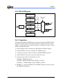
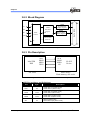
2.8.1 Block Diagram
Internal P ullup R esister
/RESET
VDD
Power-On Reset
Circuit (POR)
Brown-Out Reset
Circuit (BOR)
32K Oscillator
Reset
Internal Reset
Control
Circuit
Software Reset
(CPUCON register)
Watch Dog Timer
(WDT)
Reset
Reset By POR
Warm-Up Timer
(10-Bit)
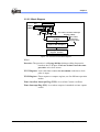
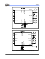
Figure 2-21 Reset System Block Diagram
eSL/eSLS Series (+ eSLZ000) User’s Manual
Architecture • 45