1
Preface
Digital’s PL-5700 series of Panel Computers (hereafter referred to as the “PL”) are
multipurpose factory automation (FA) computers, which embody Digital’s latest,
cost-effective architecture.
Before using the PL, be sure to read this manual thoroughly to familiarize yourself
with the PL’s operation procedures and functions.
The word “PL” refers to the following models:
PL-5700T1-24VC
(with CE marking)
PL-5700T1
(Standard 100V unit)
PL-5701T1
(Standard 100V unit)
PL-5700S1
(Standard 100V unit)
PL-5701S1
(Standard 100V unit)
PL-5700L1
(Standard 100V unit)
PL-5701L1
(Standard 100V unit)
NOTE:
1. It is forbidden to copy the contents of this manual in whole, or in part, without the
permission of the Digital Electronics Corporation.
2. The information in this manual is subject to change without notice.
3. This manual was written with care; however, if you should find any error or omissions, please contact Digital and inform them of your findings.
4. Please be aware that Digital is not responsible for damages resulting from the use
of our products, regardless of article 3.
5. Specifications set out in this manual are for overseas products only,and,as a
result,some differences may exist between the specifications given here and the
Japanese ones.
Product names used in this manual are the trademarks of their respective manufacturers.
© Copyright 1997, Digital Electronics Corporation
MS-DOS® and Windows® are registered trademarks of the Microsoft Corporation.
IBM® DOS® are registered trademarks of IBM.
PL-5700 Series User’s Manual
1
Preface
Safe Product Usage
This manual contains a variety of safety markings to help you safely and correctly
operate Digital’s PL-5700 series of Panel Computers, which includes the PL-5700T1,
PL-5701T1, PL-5700L1, PL-5701L1, PL-5700S1, PL-5701S1, and PL-5700T124VC. Be sure to keep this manual handy for future reference.
Safety Icons
This manual uses the two icons below to call attention to information important for the
safe and correct use of the PL. Please pay attention to these icons and follow all
instructions given by them.
The safety icons and their meanings are:
Indicates a potentially hazardous situation which could result in
serious injury or even death, if the instructions are not followed.
Indicates a potentially hazardous situation which could result in
minor injury or equipment damage if the instructions are not followed.
Essential Safety Precautions
Be sure to follow the instructions given below to ensure the safe use of the PL.
To avoid a possiblity of electrical shock, be sure to connect
the power cord to the PL before connecting it to the main
power supply.
To avoid fires or electrical shocks, do not use voltages beyond the specified range.
Before opening the PL’s protective cover, be sure to turn the
unit’s power OFF. This is because the PL’s internal parts
carry high voltages.
To avoid fires or electrical hazards, do not modify the product in any way.
2
PL-5700 Series User’s Manual
Preface
Before replacing the 100V unit’s backlight, be sure to turn
the unit’s power OFF to avoid electrical shocks. (Note: Do
NOT attempt to replace the 24V unit’s backlight)
Do not create touch panel switches that are used to either
control or to ensure the safety of equipment and personnel.
Mechanical switches, such as an emergency stop switch, a
deadman (two-handed) start switch, etc., must be installed
and operated via a separate system.
If metal particles, water or other types of liquids contact any
of the PL’s internal parts, immediately turn the unit’s power
OFF, unplug the power cord, and contact either your dealer
or Digital Electronics Corporation.
Read and understand Chapter 4 “Installation and Wiring”
thoroughly in order to select an appropriate installation location for the PL.
Before either plugging in or unplugging a board or interface
connector, be sure to turn the PL’s power OFF.
To prevent a possible explosion, do not install the PL in areas containing flammable gases.
General Safety Precautions
Follow the instructions given below for correct and safe use of the PL.
• Do not push on the PL’s screen too strongly, with either your
finger or with a hard object. Excessive pressure can
scratch, crack or damage the screen.
• If the screen becomes dirty or smudged, moisten a soft cloth
with diluted neutral detergent, wring the cloth well, and wipe
the display. Do not use thinner or organic solvents.
• Do not use a pointed object, such as a mechanical pencil or
screwdriver, to press any of the touch panel’s switches,
since they can damage the display.
• Avoid exposing and operating the PL in direct sunlight, high
temperatures and humidity, and in areas where excessive
dust and vibration will occur.
PL-5700 Series User’s Manual
3
Preface
• To prevent the PL from overheating, be sure its air circulation vents are clear and clean, and keep the unit’s operation
area well-ventilated.
• Avoid operating or storing the PL near chemicals, or where
chemicals can come into contact with the unit.
• Before the PL is initially started, be sure to install its memory
(DIM) module. If this module is not installed, the unit will not
operate.
Notes on Handling the LCD
The FP's LCD contains a strong irritant. If the panel is ever cracked and the LCD's
liquid contacts your skin, be sure to wash it with running water for at least 15
minutes. If any of this liquid should enter your eye, be sure to flush your eye with
running water for more than 15 minutes, and see a doctor immediately.
The current brightness of the LCD screen will depend on the screen's current display and the LCD's contrast adjustment. Any brightness variations that result are
normal for LCD displays (i.e. dark and light points).
There are minute grid-points on the LCD surface. These points are not defects.
Occasionally crosstalk (shadows appearing on extended display lines) will appear
on the display. This phenomenon is a common attribute of LCDs and is not a
defect.
The displayed color will look different when viewed from an angle outside the
specified view angle. This is also normal.
Displaying a single screen image for long periods of time can cause an afterimage to
remain on the screen. To correct this, turn the unit OFF for 5 to 10 minutes, then
ON again. This phenomenon is a common attribute of the LCDs, and is not a
defect. To prevent this effect, you can:
- use the Display OFF feature; if the same image is to be displayed for a long
period of time.
- change the screen display periodically to prevent the displaying of a single
image for a long period of time.
4
PL-5700 Series User’s Manual
Table of Contents
Preface
Preface ......................................................................................................... 1
Safe Product Usage...................................................................................... 2
Safety Precautions ....................................................................................... 2
Table of Contents ......................................................................................... 5
Before Using the PL .................................................................................... 8
Features........................................................................................................ 9
Unpacking the PL ........................................................................................ 10
Information Symbols ................................................................................... 10
Chapter 1 Overview
1-1 System Configuration ..................................................................................... 1-1
1-2 Options ........................................................................................................... 1-2
1-3 PL Series Panel Types .................................................................................... 1-3
Chapter 2 Specifications
2-1 General Specifications ................................................................................. 2-1
1. Electrical Specifications .............................................................................. 2-1
2. Environment Specifications......................................................................... 2-1
3. Dimensions .................................................................................................. 2-2
2-2 Performance Specifications ......................................................................... 2-3
1. Performance Specifications ......................................................................... 2-3
2. Display Functions ........................................................................................ 2-4
3. Expansion Slots ........................................................................................... 2-6
2-3 Interface Specifications ............................................................................... 2-7
1. Printer Interface ........................................................................................... 2-7
2. Keyboard Interface ...................................................................................... 2-7
3. Mouse Interface ........................................................................................... 2-7
4. RS-232C Interface (COM1/COM2) ............................................................ 2-8
5. RS-485 Interface (COM3) ........................................................................... 2-8
6. Jumper Settings ........................................................................................... 2-9
7. Using the Contrast Adjustment Knob ............................................................ 2-10
2-4 PL External Features ................................................................................... 2-11
2-5 PL Dimensions ............................................................................................ 2-13
1. PL-5700T1 PL-5700T1-24VC, PL-5700S1, PL-5700L1 : ..................................
General Dimensions ....................................................................................... 2-13
2. PL-5701T1, PL-5701S1, PL-5701L1 : General Dimensions................................ 2-14
3. Installation Hole Dimensions ...................................................................... 2-15
Series PL-5700 User’s Manual
5
Chapter 3 Installing Optional Units and Expansion Boards
3-1 Available Options and Expansion Boards ................................................. 3-1
3-2 Installing Options and Expansion Boards ................................................. 3-3
1. Installing DIM Modules (PL-EM000/EM001/EM002) .......................... 3-3
2. Installing the External Cache Memory Board (PL-EC000) .................... 3-5
3. Installing the HDD unit (PL-HD000) or the Flash File Disk Unit (PL-FF000/FF001) .. 3-6
4. Installing the FDD Unit (PL-FD000/FD001) ......................................... 3-10
5. Installing the Memory Card Interface Unit (PL-MC000) ....................... 3-13
6. Installing the IDE Slave Adapter (PL-SA000) ....................................... 3-14
7. Installing the Flash ROM Board (PL-FR000) ........................................ 3-15
8. Installing an Expansion Board ................................................................ 3-16
Chapter 4 Installation and Wiring
4-1 Installing the PL ........................................................................................ 4-1
1. Installation Procedures ........................................................................... 4-1
4-2 Wiring the PL ............................................................................................ 4-5
1. Connecting the Power Cord .................................................................... 4-5
2. Cautions: 100V PL-5700 T*/S*/L* Units .............................................. 4-7
3. Grounding Cautions................................................................................ 4-8
4. Cautions When Connecting I/O Signal Lines ......................................... 4-8
Chapter 5 System Set-up
5-1. Set-up Procedures .................................................................................... 5-1
5-2. System Parameters ................................................................................... 5-3
1. Main ........................................................................................................ 5-3
2. Advanced ................................................................................................ 5-6
3. Power ...................................................................................................... 5-8
4. Exit ......................................................................................................... 5-9
Chapter 6 Bundled Software
6-1 File List ..................................................................................................... 6-1
6-2 Touch Panel Input File .............................................................................. 6-3
1. PLATPH.EXE (Touch Panel Handler) ................................................... 6-3
2. PLCALIB.EXE (Touch Panel Data Calibration) .................................... 6-11
6-3 Other Files ................................................................................................. 6-13
1. DISP.EXE (Display ON/OFF Program) ................................................. 6-13
2. FANALARM.EXE (CPU Cooling Fan Alarm Detection Program)....... 6-13
3. BLSAVER.SCR (Windows®3.1 Screen Saver / Windows®95 Screen Saver) .... 6-13
PL-5700 Series User’s Manual
6
Chapter 7 Maintenance and Inspection
7-1 Cleaning the Display ................................................................................. 7-1
7-2 Replacing the 100V Unit’s Backlight ....................................................... 7-2
7-3 Periodic Check .......................................................................................... 7-3
Appendices
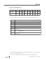
1. Hardware Configuration .............................................................................. A-1
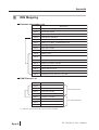
1. I/O Mapping ....................................................................................... A-1
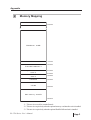
2. Memory Mapping .............................................................................. A-3
3. IRQ Mapping ..................................................................................... A-4
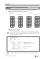
2. Serial Communications ............................................................................... A-5
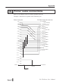
3. Printer Cable Connections ........................................................................... A-6
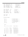
4. Touch Panel Handler Sample Program ........................................................ A-7
5. BIOS Lists ................................................................................................... A-15
Index ..................................................................................................................... i - iii
Series PL-5700 User’s Manual
7
Before Using the PL
Prior to use, be sure your PL is set up as follows.
Caution
• Before turning the PL ON, be sure to install its memory
(DIM module). If this module is not installed, the PL can be
turned on, but will not operate.
Install PL memory
Refer to 1-2 Options and the instruction manual that came
with the memory; 3-2 1. Installing the DIM Module (PLEM000/EM001/EM002); 3-2 2. Installing the External
Cache Memory Board (PL-EC000)
Install HDD unit
Refer to 1-2 Options and the instruction manual that came
with either the HDD unit; 3-2 3. Installing the HDD Unit
(PL-HD000), or the Flash File Disk Unit (PL-FF000/FF001);
3-2 4. Installing the FDD Unit (PL-FD000/FD001); 3-2 5.
Installing the Memory Card Interface Unit (PL-MC000)”;
3-2 6. Installing the IDE Slave Adapter (PL-SA000); 3-2
7. Installing the Flash ROM Board (PL-FR000)
Turn the PL ON
Refer to 4-2 Wiring the PL
System Setup
Refer to Chapter 5 System Set-up
OS Installation
Refer to the OS’s installation manual (e.g. Windows® 95
package’s manual)
• For system setup and OS installation, a PS/2 type keyboard is necessary.
• To use Windows® 3.1 or Windows® 95, install the PL-5700 Driver & Utility
Disk’s Display Driver. (For installation information, see the disk’s
README.TXT file)
• For information on the PL-5700’s bundled utility software, see the
README.TXT file on the Driver & Utility Disk.
PL-5700 Series User’s Manual
8
Special Features
The main features of PL series displays are as follows:
The Latest, High-Performance Architecture
Designed around the AMD 5x86 133 MHz CPU, the PL utilizes the type of high
performance architecture used by most PC compatibles.
Bright 10.4" LCD with a Wide Viewing Angle
The PL’s large 10.4-inch 640 ´ 480 LCD display is available with TFT or STN
color, as well as monochrome, each offering excellent visibility and brightness.
• Digital’s top of the line TFT color LCD model allows you to create detailed
and powerful visual images, with excellent brightness, a wide viewing angle,
and a display capable of 260,000 colors.
• In addition to their superior cost performance, Digital’s STN type LCDs provide a high quality color display at a reasonable price.
• The black-and-white LCD models are high-performance, low-cost displays,
equipped with a virtually maintenance-free backlight. This long lasting light
has a service life of 45,000 hours.
Easy Front Panel Installation
The PL is designed to be installed easily into the front of any panel or device. It is
also rugged enough for use in harsh, industrial environments, such as those found
in the factory automation industries.
High Resolution, Analog-Resistance-Film Touch Panel
Standard equipment with the PL is a high resolution 1024 x 1024 touch panel.
Also, the bundled Windows® 95 keyboard emulation utilities and MS-DOS®
touch-panel handler allow you to operate a variety of software applications without ever having to connect a keyboard. An optional Windows® 95 mouse emulation utility is also available.
Highly Expandable
For the easy enhancement of your PL unit, ISA-bus expansion slots are provided.
The PL-5700T1, PL-5700T1-24VC, PL-5700S1, and PL-5700L1 each provide
three ISA-bus expansion slots, and the PL-5701T1, PL-5701S1, and PL-5701L1
each provide one. These slots can accommodate both Digital’s own optional
boards as well as other commercially available expansion boards. Digital also
offers a wide variety of optional products, such as an HDD unit, an FDD unit, and
an external cache memory board.
Series PL-5700 User’s Manual
9
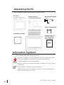
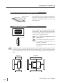
Unpacking the PL
The PL package should include the following items:
PL Unit
PL-5700T1, PL-5700T1-24VC
PL-5701T1, PL-5700S1, PL-5701S1,
Power Cord (not
included with 24V model)
Mounting Brackets
(four)
PL-5700L1, PL-5701L1
Driver & Utility Disk
Function Key Labels
Installation Gasket
When using the function keys,
attach the labels as shown below.
Panel Computer
PL-5700 Series
User’s Manual
PL-5700
User’s
Manual
Information Symbols
This manual uses the following icons.
Indicates a warning or a product limitation. Be sure to follow the instructions given with this icon to insure the safe operation of the PL.
Contains additional or useful information.
*
Indicates terms or items that require further explanation. See the footnote
on that page.
Indicates pages containing related information.
1. 2.
Indicates steps used to accomplish a given task. Be sure to follow these
steps in the order they are written.
PL-5700 Series User’s Manual
10
Chapter
1
1-1 System Configuration
1-2 Options
1-3 PL Series List
Overview
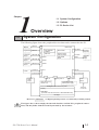
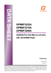
1-1 System Configuration
The following figure shows the peripheral devices that can be connected to the PL.
Mouse
PS/2 I/F
Main board
PS/2 I/F
CPU AM5x86
133MHz
DIM module
Peripheral
device
RS-232C I/F
HDD unit
External cache
memory board
Peripheral
device
RS-232C I/F
Peripheral
device
RS-485 I/F
Keyboard
Printer
COM1
Printer I/F
Flash ROM
board
5/12 VDC
output
COM2
CD-ROM
Hard disk
CD-ROM
power
supply
COM3
LCD I/F
LPT1
5/12 V DC input
12 VDC output
Inverter
power
supply
EXT-IDE I/
F
FD I/F
FDD unit/memory
card I/F unit
Touch panel I/
EXT-ISA I/F
F
Expanded mother
board (PC/AT type)
Analog resistance film touch panel
Display
Power
supply
100 V AC
or 24V DC
LCD panel
(TFT color LCD, STN color LCD, or black-and-white LCD)
Backlight
* Devices in dotted boxes are Digital optional products or commercially available products.
The figure above shows simply the internal data flow and the PL’s peripheral connections, and may differ from the actual layout used by the customer.
PL-5700 Series User’s Manual
1-1
Overview
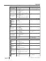
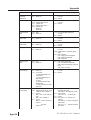
1-2 Options
The following table provides a list of optional products for the PL.
Expansion Options
Name
DIM module
Model
number
P L-EM000
P L-EM001
P L-EM002
Des cription
Main memory module
(PL-E M000 : 4 MB, PL-E M001 : 8 MB, PL-E M002 : 16MB )
E xternal cache
P L-EC000
memory board
256-K B s econdary cache board
HDD unit
PL-HD000
Dedicated HDD unit with built-in 2.5" 540 MB hard disk
P L-FD001
P C/AT compatible 3.5" FDD unit
P L-FD000
P C/A T compati ble 3. 5" FD D unit for de ve lopment a nd
maintenance
Memory card
interface unit
P L-MC000
J EIDA-compliant (Ver. 4.1) IC memory card interface
(Cannot write to flash-memory type cards )
IDE slave
adapter
P L-SA000
Adapter for atta ching IDE (ATAP I)-compliant CD-R OM drive
(DC power cord included)
P L-F F000
3-MB s ilicon disk unit compatible with hard disks
P L-F F001
10-MB silicon dis k unit compatible with hard dis ks
P L-FR000
F la sh ROM board which accommodates up to two 2-MB R OM
drives. One drive can be as s igned to drive A: or B: (the OS
s tarts from drive A: only). The other drive can be as s igned to
drive C: or later. Each disk can be s eparately programmed.
(FR OMDISK Programming Tool included.)
F DD unit
F la sh file disk
unit
F la sh ROM
board
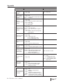
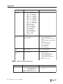
Accessories
Name
Model numbe r
Screen
P L-CS001
protection sheet
Desc ription
D is posa ble ove rlay she e ts for dis play prote ction and s ta in
res is tance. Touch panel switches will still s ense your touch when
the sheet is in place.
Maintenance Options
Name
Model number
Desc r iption
Backlight
G P570-B L00-MS
R eplacement backlight available for TFT and S TN color
LCDs.
Mounting
brackets
G P070-AT00-MS
Hardware for installing the PL . S ame a s P L's origina l
brackets.
Moisture
res is tant
packing
GP570-WP00-MS
Moisture res is tant packing used when ins talling the PL .
S ame as P L's original packing.
Software Options
TT-WIN for Windows® 3.1
TT-W IN for Windows® 95
1-2
Mouse emulation utilities for the touch panel's screen
PL-5700 Series User’s Manual
Overview
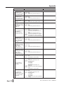
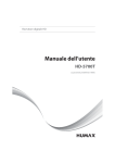
1-3 PL Series Panel Types
Model number
P L - 5 7 0 0 T 1-24VC*
PL-5700 series
^
^ ^
Display type
L : Black-and-white LCD
S : STN color LCD
T : TFT color LCD
Expansion slots
0 : 3-slot type
1 : 1-slot type
Expansion Slots
* if “24VC” is not
1-Slot type
3-Slot Type
STN color LCD
PL-5701L1
PL-5701S1
TFT color LCD
PL-5701T1
PL-5700L1
PL-5700S1
PL-5700T1/
PL5700T1-24VC
Display
B/W LCD
PL-5700 Series User’s Manual
written, the unit is
100V type.
1-3
MEMO
This page is intentionally left blank.
PL-5700 Series User’s Manual
1-4
Chapter
2
2-1 General Specifications
2-2 Performance Specifications
2-4 PL External Features
2-3 Interface Specifications
2-5 PL Dimensions
Specifications
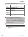
2-1 General Specifications
1
Electrical Specifications
Power s uppl y
vo ltage
85 - 132 VAC, 50/60 Hz
Power
c onsumption
P L-5700T1, P L-5700S1, P L-5700L1 : Max. 150 VA
P L-5701T1, PL-5701S 1, PL-5701L1 : Max. 120 VA
Allowable
dropped voltage
time
Max. 20 ms
With s tand
voltage
1500 VAC , 20 mmA for one minute (between charging terminal and FG
terminal)
Ins ulation
res is tanc e
Min. 10MW at 500 V DC (between charging terminal and FG terminal)
Panel Computer PL-5700 Series User’s Manual
2-1
Specifications
2
Environment Specifications
Operatin g amb ient
temp erature
PL-5700T1, PL-5701T1 : 0 ˚C 4 to 5˚C
PL-5700S1, PL-5701S1, PL-5700L1, PL-5701L1 : 0 ˚C to 40˚C
Ambient h umidity
30%R H- 85 %R H(non condens ing)
S torage temperatu re
-10˚C to 60˚C
Operating ambient
atmos phere
F ree of corros ive gas
Noise immunity
(tested by nois e
s imulato r)
Noise voltage : 1500Vp-p
P ulse duration : 50 ns, 500 ns, 1µs
E le ctrostatic
with s tand voltage
5 kV
V ibration resistance
2G : at 10 to 25 Hz applied in X, Y, and Z directions for 30 minutes each
(0.5 G when us ing HDD unit, and 1.0 G when us ing F DD unit)
G round
100Ω or les s ,or your country's applicable s tandard.
R ating
E quivalent to IP65F (JE M1030)
Be sure to check the specifications of any optional products used.
Also, if the temperature of the PL’s electrical cooling fins reaches 100 (+/- 15)
degrees, the PL’s saftety feature will automatically activate, turning the PL OFF.
Thus, since these fins are usually 25 degrees hotter than the surrounding
atmoshpere, once the area surrounding the PL reaches apporoximately 60 degrees, this safety feature will activate.
Once the temperature of these fins falls below 60 degrees, the unit can be restarted and operation resumed.
3
Dimensions
Extern al
PL-5700T1, PL-5700S1, PL-5700L1 : 321 mm (W) x 272 mm (H) x 129.3 mm (D)
dimensi ons PL-5701T1, PL-5701S1, PL-5701L1 : 321 mm (W) x 272 mm (H) x 96.3 mm (D)
Weight
2-2
P L-5700T1, P L-5700S1 : 5.5 kg
P L-5701T1, PL-5701S 1 : 4.6 kg
P L-5700L1 : 4.7 kg
P L-5701L1 : 3.8 kg
(excluding acces s ories)
PL-5700 Series User’s Manual
Specifications
2-2 Performance Specifications
1
Performance Specifications
CPU
AMD 5x86 (133 MHz) manufactured by AMD
NDP
Not Applicable (Built into C PU)
DRAM (Main memory)
0 MB (Two DIMM sockets : Max. 32 MB memory )
B IOS
P hoenix (P C compatible)
Meth od
Touch-pan- R es olution
el
Effec tive
area
S erial
Interface
PL-5700 Series User’s Manual
Analog res is tance film s ys tem
1024 x 1024
10.4" screen and surrounding function-key areas
R S-232C
R S-485
C OM1
DB 9-pin male connector
C OM2
DB 9-pin male connector
C OM3
Terminal board
P rinter
C entronics s tandard (DB 25-pin female connector)
K eyboard
P S/2 interface (Mini DIN 6-pin female connector)
Mouse
P S/2 interface (Mini DIN 6-pin female connector)
2-3
Specifications
2
Display Functions
PL-5700T1, PL5701T1
P L -5 700S1, P L5701S 1
P L -5 700L1, P L5701L 1
Dis play device
TFT color LCD
S TN color LCD
Black and white LCD
P ix el configuration
640 x 480 pixels
640 x 480 pixels
640 x 480 pixels
Effec tive area
221.1(W) x 158.4 (H)
mm
215.1 (W) x 162.3 (H)
mm
216.0 (W) x 160.8 (H)
mm
Dot p itc h
0.33 x 0.33 mm
0.33 x 0.33 mm
0.33 x 0.33 mm
C olor resolution
260,000colors
8 colors (halftone by
thinned-out frame)
2 colors (halftone by
thinned-out frame)
C ontras t adjus tment
F ixed
8 levels
8 levels
B rightnes s adjus tment
F ixed
Fixed
2 levels
(Standard/High)
Maintenance
(backlight life)
R eplaceable backlight R eplaceable backlight
lamp (20,000hours )
lamp (20,000hours )
Non-replaceable
backlight lamp
(Standard brightness :
45,000hours ,
High brightnes s :
25,000hours )
Backlight life is designated as the number of hours until the brightness drops to half
of the maximum level, in a 25°C environment. Before leaving images on the display
for an extended period of time, turn the backlight off if at all possible.
For information about how to replace the backlight, see “7-2 Replacing the 100V
Unit’s Backlight.”
ll Display Colors
• Uneven brightness, flickering, or ghosts (caused by cross talk) may occur with the
PL-5700S1, PL-5701S1, PL-5700L1, and PL-5701L1, depending on the display colors (especially halftones) or color combinations used. This, however, is a basic characteristic of this type of display, not a defect. Since this flickering can sometimes be
caused by the combination of display colors used, selecting other colors may improve
the display quality.
• The higher the contrast between the foreground and background colors is, the more
likely that crosstalk will occur. Either changing the color combination or decreasing
the contrast may help to reduce the amount of cross talk.
See “5-2, System Parameters.”
2-4
PL-5700 Series User’s Manual
Specifications
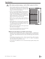
I For black-and-white displays : the PL-5700L1 and the PL-5701L1
• If VGA 16-color standard pallet colors are used on a
black-and-white display, brightness will increase in
order of the pallet numbers, i.e. from 0 (black) to 15
(white). It is not recommended to use those colors
marked with asterisks (*) (shown in the figure to the
right), since they often cause flickering.
• Pallet colors 2, 6, and 9 may be hard to identify on
the screen, since they have almost the same level of
brightness.
• Some combinations of colors may not be easy to identify. Whenever you are developing an application it
is recommended that you frequently test how your
program will appear on the PL.
VGA 16-color standard pallet
0 Black
1Blue
4 Red
5 Magenta
8 Black
6 Yellow
2 Green
9 Blue
3 Cyan
12 Red
13 Magenta
7 White
10 Green
11Cyan
14 Yellow
15 White
Dark
Dark
Dark
Dark
Bright
Dark
Dark
Bright
Dark
Bright
Bright
Dark
Bright
Bright
Bright
Bright
*
*
*
Darker
^
*
*
*
*
*
^
• These displays normally use only black and white,
with grey tones being produced by making the dots
flash. This display method, however, may cause flickering to occur with certain halftones.
Brighter
• Black-and-white tiled displays often appear better
than multi-colored displays.
• If you wish to use halftones, be sure to check their
display quality during actual PL operation.
I
I STN color LCD displays: PL-5700S1 and PL-5701S1
• STN color LCDs use three primary colors - red, green, and blue - to display up to
8 different colors. Halftones are produced by making the dots used in these three
colors flash. This mechanism, however, may cause flickering with certain halftones.
• Tiled displays using only pure colors - black, red, green, blue, yellow, magenta,
cyan, and white (pallet numbers 0, 12, 10, 9, 14, 13, 11, and 15) - may appear
better than displays using different colors.
• If you wish to use halftones, be sure to check their display quality during actual
PL operation.
PL-5700 Series User’s Manual
2-5
Specifications
3
Expansion Slots
• The PL does not supply -5 or -12 V. As a result, ISA (AT) bus compatible boards
which require -5 or -12 V are not available.
• All the DB connectors for external interfaces are equipped with inch type connector
screw threads.
2-6
PL-5700 Series User’s Manual
Specifications
2-3
1
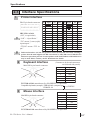
Interface Specifications
Printer Interface
DB-25 pin female connector
Pin
No.
13 12 11 10 9 8 7 6 5 4 3 2 1
25 24 23 22 21 20 19 18 17 16 15 14
JBY-25S-1A3A14,
(J.S.T, or equivalent)
“O.D” = “Open Drain.”
“T.S” means “3-state (triple)
input/output.”
“TTLIN” means “TTL input.”
Signal
I/O
Spec.
Pin
No.
Signal
I/O
Spec.
1 STROBE
Output
O.D
14 AUTOFD
Output
O.D
2
DATA0
Output
T.S
15
ERROR
Input
TTL IN
3
DATA1
Output
T.S
16
INIT
Output
O.D
4
DATA2
Output
T.S
17
SLCTIN
Output
O.D
5
DATA3
Output
T.S
18
GND
6
DATA4
Output
T.S
19
GND
7
DATA5
Output
T.S
20
GND
8
DATA6
Output
T.S
21
GND
9
DATA7
Output
T.S
22
GND
10 ACKNLG
Input
TTL IN
23
GND
11
BUSY
Input
TTL IN
24
GND
12
PE
Input
TTL IN
25
GND
13
SLCT
Input
TTL IN
Dedicated windows (95, 98, NT) printers cannot be used. Be sure when selecting a
printer that the unit supports the HP LaserJet PCL, NEC PR series, EPSON ESC/
P24-84 or equivalent protocol. Certain printers with both Windows and DOS drivers
may be used. Please contact your PL distributor for details.
2
Keyboard Interface
Mini DIN 6-pin female connector
5
6
4
2
1
3
(Common to keyboard connectors
on front and side panels)
Pin No.
Signal
1
KEY DATA
2
NC
3
GND
4
+5V
5
KEY CLK
6
NC
TCS7568-43-201 manufactured by HOSHIDEN, or equivalent
Compatible keyboards (example) : FKB1424-001 (compact type)
by FUJITSU
FKB4874-101
3
Mouse Interface
Mini DIN 6-pin female connector
5
6
4
2
1
3
Pin No.
Signal
1
MOUSE DATA
2
NC
3
GND
4
+5V
5
MOUSE CLK
6
NC
TCS7568-43-201 manufactured by HOSHIDEN, or equivalent
PL-5700 Series User’s Manual
2-7
Specifications
4
RS-232C Interface (COM1/COM2)
DB 9 pin male connector
1 2 3 4 5
6 7 8 9
Pin No.
Signal
Pin No.
Signal
1
CD
6
DSR
2
RXD
7
RTS
3
TXD
8
CTS
4
DTR
9
RI/(5V)*1
5
GND
JEY-9P-1A3A14 - by J.S.T, or equivalent
*1 : With COM2, pin 9 can be configured for +5 V output, via a jumper.
See next page’s “2-3, 6 Jumper Settings”.
5
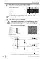
RS-485 Interface (COM3)
This unit’s RS-485 (RS-422) Port is not isolated, therefore, it is crucial that you connect the SG/GND (Signal
Ground) terminals. If this is not done, the RS-485 (RS422) circuit may be damaged.
7
6
5
4
3
2
1
M3 screws
Pin No.
Signal
1
TD-
2
RD-
3
TD+
4
RD+
5
GND
6
FG
7
NC
<Interface Circuit>
SN751178N or equivalent
J9
TXD
220
TD+
TD-
DTR
J10
RXD
220
RD+
RD-
GND
FG
Use the GND and FG terminals only when the connected device requires them.
2-8
PL-5700 Series User’s Manual
Specifications
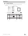
6
Jumper Settings
Before setting the jumpers, remove the unit’s rear maintenance panel.
PL Rear Panel
J10
J9
J5
In the drawing below,
indicates an open jumper.
Jumper
indicates a shorted jumper, and
Setting
Factory-default
COM2: To set pin 9 to:
J5
1
2
3
1
2
3
1
2
3
RI input
5 V output
J9
RS-485 output-side terminator
J10
RS-485 input-side terminator
PL-5700 Series User’s Manual
RI input
Terminator enabled
Terminator enabled
2-9
Specifications
7
Using the Contrast Adjustment Knob
Four of the PL displays (5700L1, 5701L1, 5700S1 and 5701S1) have a contrast control knob so that you can adjust the display’s contrast as desired. Digital requests,
however, that you use the SETUP utility, CONTSET.EXE, or WCONTSET.EXE for
contrast adjustment, instead of this contrast knob.
See “5-2, 1. Main
Backlight/Contrast,” and “6-1 File List.”
Normally, contrast adjustments are not required, since the contrast level is factory-set
at a normally optimal level.
Adjusting the Unit’s Contrast
Bottom View
1. Loosen the dummy unit’s six attachment
screws, located on the bottom and side of
the PL.
Side View
Remove the dummy
unit.
^
To increase the contrast, rotate the control
clockwise. To decrease it, rotate the control
counter-clockwise.
2-10
PL-5700 Series User’s Manual
Specifications
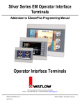
2-4 PL External Features
A B
C
Inside the front maintenance cover
E
D
F
G
H
I
J
This figure shows the PL-5700 T1
K
A. Display area
Display output area. The built-in VGA controller supports PC compatible architecture.
B. Touch panel
This high-resolution analogue touch panel allows you to configure a keyboard-less system.
C. Front maintenance cover
Remove this cover to connect the optional FDD
unit or memory card interface unit.
D. Keyboard connector
A PS/2 compatible keyboard can be connected
here.
E. Floppy disk/memory card insertion slot
This slot is used if the optional FDD unit or
memory card interface is installed.
F. Backlight replacement cover
Remove this hatch to replace the backlight. (With
black-and-white LCDs, the backlight is NOT
replaceable.)
G. RS-485 connector (COM3)
RS-485 interface, which allows communication
with other computers or connection to peripheral devices.
H. RS-232C connector (COM1)
I. RS-232C connector (COM2)
RS-232C interfaces (DB 9-pin male connectors),
which allow communication with other computers or connection to peripheral devices.
J. Printer connector (LPT1)
Centronics standard interface (DB 25-pin female
connector), which connects a parallel device,
such as a printer.
K. Expansion slot
A variety of expansion boards, both Digital’s and
other companies, can be installed here.
See “3-1 Available Options and
Expansion Boards”
The PL-5700T1-24VC, PL-5700T1, PL-5700S1, and PL-5700L1 each have three slots, designated as “slot 1,” “slot
2,” and “slot 3,” starting from the one closest to the front panel. The PL-5701T1, PL-5701S1, and PL5701L1 provide
one slot, designated as “slot 1.”
PL-5700 Series User’s Manual
2-11
Specifications
L
M
N
L. HDD cover
Remove this cover to install the HDD unit.
M.Mouse connector
A PS/2 compatible mouse can be attached
here.
N. Keyboard connector
A PS/2 compatible keyboard can be attached here.
O. Dummy unit
Remove this unit when attaching the FDD
unit or memory card interface unit.
O
This figure shows the PL-5700 T1
P. Rear maintenance cover
Remove this cover to install the optional
external cache board, flash ROM board,
or DIM module.
Q. Power switch
Use this switch to turn the PL’s power ON
or OFF.
P
This figure shows the PL-5700 T1
Q
R. Power input terminal strip
100V AC unit - connect the provided
power cord here.
R
24V DC unit - connect the customer’s provided cord here.
To avoid danger of electrical shocks or fire, be sure to turn the PL’s power OFF before
connecting the power cord or any peripheral devices to the PL.
2-12
PL-5700 Series User’s Manual
Specifications
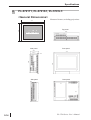
2-5 PL Dimensions
1
PL-5700T1-24VC, PL-5700T1, PL-5700S1, PL-5700L1:
<General Dimensions>
(Measured in mm, excluding projections)
312
Top panel
272
290
Effective area
211.2 (W) x 158.4 (H)
Side panel
Front panel
129.3
312
13.2
272
250
(116.1)
Side panel
PL-5700 Series User’s Manual
Rear panel
2-13
Specifications
2
PL-5701T1, PL-5701S1, PL-5701L1:
<General Dimensions>
Measured in mm, excluding projections
272
312
Top panel
Effective area
290
211.2 (W) x 158.4 (H)
Side panel
Front panel
96.3
312
13.2
272
250
(83.1)
Side panel
2-14
Rear panel
PL-5700 Series User’s Manual
Specifications
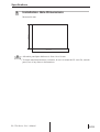
3
Installation Hole Dimensions
Measured in mm
252.0 +0.5
^
^
^
^
292.0 +0.5
• Allowable panel/plate thickness is from 1.6 to 10 mm.
• To obtain maximum moisture-resistance, be sure to mount the PL on a flat, smooth
panel, free of any dents or deformations.
PL-5700 Series User’s Manual
2-15
Specifications
MEMO
This page intentionally left blank.
2-16
PL-5700 Series User’s Manual
Chapter
3
3-1 Available Options and Expansion Boards
3-2 Installing Options and Expansion Boards
Installing Optional Units
and Expansion Boards
The PL can be equipped with Digital’s optional units and expansion boards, as well
as a variety of commercially available ISA-bus compatible boards. This chapter describes both the products that can be installed in the PL and their installation methVGA
3-1 Available Options and Expansion Boards
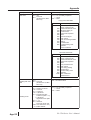
Optional Products
Name
Model
DIM module
P L-EM000
P L-EM001
P L-EM002
Main memory board
(PL-E M000 : 4MB
(PL-E M001 : 8MB
(PL-E M002 : 16 MB )
E xternal
cache
memory
board
P L-EC000
256-K B s econdary cache memory board Inside the P L
HDD unit
PL-HD000
D edic ate d HD D unit with built-in 2 . 5 " Ins ide the PL
810-MB hard dis k
P L-FD000
Ins ide the PL . This unit cannot
P C/AT compatible, 3.5" F DD integrated be
ins talled at the s ame time as
unit
the memory card interface unit.
P L-FD001
E xte rnally c onnec te d. Us ea s
e ithe r a sta nd - alo ne uni t o r
P C/A T compati ble , 3 . 5 " F DD uni t f or atta ch to P L's rear panel. The
memory card interface unit can
development and maintenance
be als o used, when this unit is
ins talled.
Memory card P L-MC000
interface unit
Ins ide the PL. This unit cannot
J EIDA (V er 4.1)-complia nt IC me mory be
ins talled at the s ame time as
card interface
the memory card interface unit.
IDE slave
adapter
P L-SA000
Adapter for connecting an IDE-compliant E xternally connected. Connects
C D-ROM drive. DC power cord included. to P L's IDE connector.
P L-FR000
F la sh ROM board which accommodates
up to two 2-MB ROM drives. One drive
can be assigned to drive A: or B: (the OS
starts from drive A: only). Another drive can Ins ide the PL.
be as s ig ne d to drive C: or succeeding
characters (i.e. D:, E :, etc.). Each disk used
c a n b e s e p a ra te ly p r o g r a m m e d .
(FR OMDISK Programming Tool included.)
P L-F F000
3MB silicon dis k unit compatible with hard Ins ide the PL.
dis ks
P L-F F001
10MB s ilicon disk unit compati ble with Ins ide the PL.
hard dis ks
F DD unit
F la sh ROM
board
F la sh file disk
unit
PL-5700 Series User’s Manual
Desc ription
Ins tallation L oc ation
Ins ide the PL
3-1
Optional Units and Expansion Boards
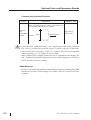
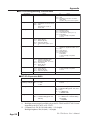
Commercially Available Products
Produc t
Des cription
Installation Area
Slot 1 on all PLs can accommodate boards up to 210 mm
wide. For 3-slot type PLs (PL-5700*1), slots 2 and 3 can
accommodate boards up to 160 mm wide.
^
Width
Mount facing this
P lugs into PL's
expansion slot.
^
ISA (AT)
bus
c ompatible
board
direction
^
• Check that your expansion board’s “foot” matches the width of the expansion
slot. Slot 1 is 20 mm wide, and slots 2 and 3 (3-slot PLs only) are 25 mm wide.
• Since the PL does not supply -5 and -12 V current, ISA(AT)-bus compatible
boards requiring -5 or -12 voltage are not available.
• Other commercially available boards may not be compatible with Digital’s PL
unit. Installing incompatible boards may result in either damage to or failure of
the PL and will void your warranty.
<Main Memory>
Be sure to use only DIM modules manufactured by Digital. Installing other DIM
modules may result in either damage to or failure of the PL, and will void your
warranty.
3-2
PL-5700 Series User’s Manual
Optional Units and Expansion Boards
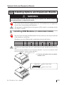
3-2 Installing Options and Expansion Boards
WARNING
To avoid electric hazards, be sure to turn the PL’s power OFF before installing
any optional units or expansion boards.
Use a screw driver to loosen or tighten the screws. Be careful not to over-tighten any
screws, since it may damage the equipment.
The procedures explained in this section apply to all PL models, even though only the
PL-5700T1 is shown.
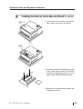
1
Installing DIM Modules (PL-EM000/EM001/EM002)
Be careful when inserting the DIM module into the socket since the clips at both ends
of the module are easily bent.
Determine your unit’s DIM module combination from the table below.
Total capacity (MB)
4
8
12
16
20
32
B ANK 0
4
4
8
4
8
16
4
8
16
B ANK 1
-
4
-
8
8
-
16
16
16
Installing one 8-MB module and one 16 MB module provides 20 MB of memory, not 24
MB.
If you use only one module, be sure to install it in BANK 0. If you use two modules, install
the first in BANK 0, and the second in BANK 1.
Rear maintenance cover
1. Unscrew and remove the rear maintenance cover.
DIMM sockets
BANK 1 (Upper socket)
BANK 0 (Lower socket)
PL-5700 Series User’s Manual
3-3
Optional Units and Expansion Boards
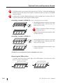
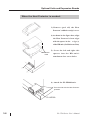
The DIM module can be inserted and removed up to 20 times. Repeated handling may
bend the clips on both edges of the module. Hold the module at an angle to the DIMM
socket to insert it.
Commercially available DIM modules may result in malfunction or failure of the PL,
if specifications differ from Digital’s DIM modules.
<Installing a module in BANK 0>
(NOTE: These figures show the PL-EM002)
2. Hold the DIM module connector at an angle
to the DIMM socket, and insert the connector into the socket
Be sure to hold the module at an angle
when inserting it.
3. Push the DIM module inward until the clips
on both ends lock.
<Installing a module in BANK 1>
2. Hold the DIM module connector at an angle
to the DIMM socket, and insert the connector into the socket.
3. Push the DIM module inward until the clips
on both ends lock.
4. Refit the rear maintenance hatch, and tighten the screw.
<Removing the DIM module>
Carefully spread the clips on both edges of the DIM module, in the direction of the
arrows, to remove the module.
Removing from BANK
1
^
^
3-4
^
^
Removing from BANK
0
PL-5700 Series User’s Manual
Optional Units and Expansion Boards
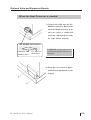
2
Installing the External Cache Memory Board (PL-EC000)
Rear
maintenance
hatch
1. Unscrew the screw on the rear maintenance hatch and remove the hatch.
Cache
board
connector
2. Attach the external cache memory board
to the cache board connector, and lock
it down by tightening the two screws
which came with the memory board.
3. Refit the rear maintenance hatch, and
retighten the screw.
PL-5700 Series User’s Manual
3-5
Optional Units and Expansion Boards
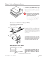
3
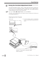
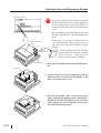
Installing the HDD unit (PL-HD000), or Flash File
Disk Unit (PL-FF000/FF001)
1. Loosen the attachment screw on the side
panel of the PL to remove the HDD cover.
Note: This drawing shows the PL-5700T1 unit (3-slot type)
HDD cover
Remove the HDD cover.
HDD connector
2) Insert the PL-HD000 unit’s attachment
cable into the HD connector. Be sure the
cable’s red
line is facing the direction
shown here.
Red Line
3-6
PL-5700 Series User’s Manual
Optional Units and Expansion Boards
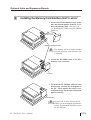
When the Heat Protector is NOT Needed
Be sure the side
with the seal is
facing up.
3) Attach the PL-HD000 and secure it in
place with the two screws given.
PL-HD000
4) Insert the cable into the PL - HD000 unit’s
connector. Be careful that the pins are
aligned as shown in the drawing here. (The
four pins on the far right will be unused)
<PL-HD000 Connector>
Connect the
cable to here
Do not use
these pins
CAUTION: If the pins are inserted incorrectly, the unit may
be damaged
5) Place the cover back in
place, and fasten its screws.
PL-5700 Series User’s Manual
3-7
Optional Units and Expansion Boards
When the Heat Protector is needed:
3) Remove (peel off) the Heat
Protector’s adhesive strip’s cover.
4) As shown in the figure here, align
the Heat Protector’s bent edges
with the spaces in the
edge(s)
of the HD unit. (See Reference Line)
5) Screw the left and right side
Reference
Line
spacers into the HD unit’s
attachment face screw holes.
6) Attach the PL-HD000 unit.
Face the side with the Heat Protector
upwards
PL-HD000
3-8
PL-5700 Series User’s Manual
Optional Units and Expansion Boards
When the Heat Protector is needed:
7) Connect the cable into the PLHD000’s connector. Refer to the
left-hand detail drawing to be
sure the cable is connected
correctly. (The four pins on the
far right will be unused)
<PL-HD000 Connector>
Connect the
cable to here
Do not use
these pins
CAUTION: If the pins are inserted incorrectly, the unit may be
damaged
8) Place the cover back in place,
and fasten its attachment screws
in place.
PL-5700 Series User’s Manual
3-9
Optional Units and Expansion Boards
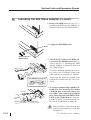
4
Installing the FDD Unit (PL-FD000/FD001)
Built-in Type (PL-FD000)
Bottom panel of the PL
1. Loosen the six screws on the bottom and
side panels of the PL, to remove the
dummy unit.
Side panel of the PL
If the PL-FD000 is installed, the
dummy unit will no longer be necessary.
Remove the dummy
unit.
FDD connector
2. Attach the PL-FD000 cable to the FDD
connector.
PL-FD000
3-10
PL-5700 Series User’s Manual
Optional Units and Expansion Boards
3. To install the PL-FD000, slide the unit
down toward the front panel of the PL.
Tighten the six screws on the side and
bottom panels.
• Be careful not to pinch the cable between the PL body and FDD unit.
This may damage the cable.
• The rear maintenance hatch may not
have screw holes depending on the
date of purchase of the PL. If so,
contact a Digital Service Center.
Development and Maintenance Type (PL-FD001)
Attaching the mounting hardware
To attach to the rear panel
To install the PL-FD001 on the REAR panel
of the PL, use the four screws which came
with the FDD unit to attach the mounting
brackets on the top and bottom panels of
the FDD unit.
To attach to the side panel
To install the PL-FD001 on the PL’s other
panel, use the four screws which came with
the FDD unit to attach the mounting brackets on the side panels of the FDD unit
When attaching to the PL Chassis
Bottom panel of the PL
1. Loosen the six screws on the side and
bottom panels of the PL to remove the
dummy unit or optional PL-MC000
unit.
The figure shows the 3-slot type of PL-5700T1
PL-5700 Series User’s Manual
3-11
Optional Units and Expansion Boards
Side panel of the PL
• To prevent short circuits with the expansion
board inserted in the slot, use only the plastic
screws which came with the PL-FD001 to
mount the FDD unit on the rear maintenance
cover.
• Be careful not to pinch the cable between the
PL body and FDD unit. This may damage the
cable.
• If the cable is too long or contacts the 100
VAC input terminals and AC power cord, secure the cable with the PL-FD001’s cable
clamps.
Rear maintenance
cover
Remove
the dummy unit
FDD connector
• When installing the PL-MC000,
keep the cable away from the memory
card’s interface. Otherwise, the
memory card cannot be installed.
2. Insert the PL-FD001 cable into the FDD connector.
PL-FD001
3. Use the four plastic screws which came with the
FDD connector to attach the PL-FD001 to the
PL’s rear maintenance cover.
4. Take the PL-FD001 cable out as shown in the
figure, and slide the dummy unit or optional PLMC000 toward the front panel to set it in place.
Then, tighten the six attachment screws on the
PL’s side and bottom panels.
3-12
PL-5700 Series User’s Manual
Optional Units and Expansion Boards
5
Installing the Memory Card Interface Unit (PL-MC000)
1. Loosen the six attachment screws on the
side and bottom panels of the PL to remove the dummy unit. (See step 1 in
“4. Installing the FDD Unit (PL-FD000/
FD001)”)
Remove the
dummy unit.
Memory Card Connector
The dummy unit is no longer needed
after the memory card interface unit
is installed.
2. Attach the PL-M000 cable to the PL’s
memory card connector.
PL-MC000
3. To insert the PL-MC000, slide the unit
downwards, towards the front panel of
the PL. Then, tighten the unit’s six attachment screws on the side and bottom
panels of the PL.
Front Panel
If you plan to also install the PLFD001 (for development and maintenance), first attach the PL-FD001, then
the PL-MC000.
PL-5700 Series User’s Manual
3-13
Optional Units and Expansion Boards
6
Installing the IDE Slave Adapter (PL-SA000)
1. Remove the HDD cover. See step 1 in “3
Installing the HDD unit (PL-HD000), or
Flash File Disk Unit (PL-FF000/FF001).”
2. Unplug the PL-HD000 cable.
PL-HD000
Remove the PLHD000 cable
To the
DC OUT
connector
^
^
(top)
^
To the
PL-HD000
DC power cord
(top)
To
the HDD
connector
(bottom)
3. Attach the PL-SA000 to the HDD connector and PL-HD000 connector (see
steps 2 and 4 in “3. Installing the HDD
unit (PL-HD000), or Flash File Disk Unit
(PL-FF000/FF001).”
If you have difficulty inserting the connector, remove the PL-HD000, connect the
cable, and then re-install the PL-HD000.
Red line
<PL-HD000 Connector>
PL-SA000
For DC OUT
connector
For PL-HD000
connector
^
To DC INPUT
^
CD-ROM
drive
To IDE
INTERFACE
Connect the DC power cord which came
with the PL-SA000 to the DC OUT connector.
CD-ROM drive
connection cable
4. To connect a commercially available CDROM drive, first attach the PL-SA000’s
CD-ROM drive connection cable to the
PL-SA000. Then, connect the CD-ROM
drive connection cable to the IDE INTERFACE on the CD-ROM drive. Last, connect the DC power cord to both the DC INPUT on the CD-ROM drive and the PL.
Make sure that pin 1 of the CD-ROM drive
connection cable matches pin 1 of the IDE
INTERFACE.
3-14
PL-5700 Series User’s Manual
Optional Units and Expansion Boards
7
Installing the Flash ROM Board (PL-FR000)
Rear maintenance
cover
1. Loosen the attachment screw on the rear
maintenance cover and remove the cover.
Optional-board connector
2. Attach the PL-FR000 to the optionalboard connector, and lock it in place with
the four mounting screws which came
with the PL-FR000.
PL-FR000
PL-5700 Series User’s Manual
3. Replace the rear maintenance cover and
tighten the screw.
3-15
Optional Units and Expansion Boards
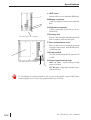
8
Installing an Expansion Board
1. Loosen the two screws of the unused expansion slot to remove the filler strip.
Remove filler strip
2. Insert the expansion board into the expansion slot.
Insert here
Expansion
board
3. Secure the board in place with the two
mounting screws.
Expansion
board
Re-attach the
filler strip
removed in step 1
3-16
If your expansion board does not have a
front panel, fasten it in place with the PL’s
internal screw holes, and externally, attach
screw (1) which came with the expansion
board. Then, replace the filler strip and
tighten the strip’s two screws.
PL-5700 Series User’s Manual
Chapter
4
4-1
Installing the PL
4-2
Wiring the PL
Installation and Wiring
This chapter describes how to install and wire the PL.
4-1 Installing the PL
1
Installation Procedures
Install the PL following the instructions given below.
Screw in the front maintenance hatch’s attachment screws
To improve the PL’s moisture and dust resistance, secure the PL’s front maintenance
cover in place before installing the PL into a control or operation panel. (This provides protection equivalent to IP65F. If merely clipped on, the protection level is
equivalent to IP63F)
Insert these two screws
To access the maintenance cover’s attachment screw holes, first remove either the
dummy or optional unit, located in the rear
of the PL (see step 1 in “3-2-4 Installing
the FDD Unit”). This will expose the front
maintenance cover’s attachment screw
holes. (See figure on left) Then, use a
screwdriver to insert the two cover attachment screws into their respective cover
holes (use only M3x6 screws). When the
maintenance cover is secured, replace the
Front maintenance cover
previously removed unit.
Panel Computer PL-5700 Series User’s Manual
4-1
Installation and Wiring
Press the moisture resistant packing into place
Rear
panel
Place the PL on a level surface with the display panel facing downward. Fit the PL’s
moisture resistant packing into the resin
bezel’s groove.
Moisture resistant
packing
Create a mounting hole
Panel
Create a hole for mounting the PL, like that
pictured here. These two items, the moisture
resistant packing and the mounting brackets are
required when installing the PL.
Mounting hole
See “2-5 External Appearance and
Dimensions”
> < 1.6 - 10.0 mm
• To obtain the maximum level of moisture resistance, mount the PL on a
smooth, flat surface.
><
• The panel itself can be from 1.6 to 10
mm thick.
• To enhance the PL’s maintainability, operability and ventilation, allow at least 50 mm
or more clearance between the PL and any other objects. (The clearance must be
large enough to allow you to insert or remove expansion boards and to attach connectors.)
Rear panel
Side panel
^
^
^
^
50mm
^
^
^
^
^
50mm
50mm
^
^
50mm
^
50mm
50mm
^
50mm
^
PL-5700 Series User’s Manual
4-2
Installation and Wiring
• The PL is intended to be mounted vertically, to allow natural ventilation. The PL can
also be tilted up to 30 degrees, if needed.
OK
OK
OK
• Avoid placing the PL next to other devices that
might cause overheating.
• The PL’s operating temperatures are a maximum 40°C for the PL-5700T1-24VC, PL570*S1 and PL-570*L1, and 45°C for the PL570*T1.
• Keep the PL away from arc-generating devices such
as magnetic switches and non-fuse breakers.
Must be 30
degrees
or less
Insert the PL into the front of the mounting panel
Mounting panel
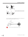
Side panel
Secure the rear panel of PL in place with the mounting brakets (4)
Hook the mounting brackets into the two mounting holes on the top face, and the two
holes on the bottom face of the PL’s body.
1.
Mounting hole
(Top and bottom faces)
PL-5700 Series User’s Manual
4-3
Installation and Wiring
Mounting panel
2.
Mounting
bracket
Hook
Front
panel
Mounting
hole
3.
Rear
panel
Insert the mounting bracket into the mounting hole, and slide the bracket backwards.
Use a driver to tighten the bracket’s adjustment screw. To ensure a high degree of
moisture resistance, the torque should be 0.5 to 0.6 N.m.
Panel
PL
Excessive torque may damage the panel or bracket.
PL-5700 Series User’s Manual
4-4
Installation and Wiring
4-2 Wiring the PL
1
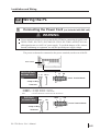
Connecting the Power Cord (not included with 24V unit)
WARNING
To prevent electric shocks, be sure to turn the PL OFF before connecting the power cord.
The PL-5700T1, PL-5701T1, PL-5700S1, PL-5701S1, PL-5700L1, and PL-5701L1 are
all designed to run on a 100V AC power supply. To avoid the dangers of fire, electric
hazards, and damage to equipment, use only the specified power supply voltage.
The power cord must be connected to the power terminals, on the rear of the PL.
Power switch
100V AC Unit
PL-5700T*/S*/L*
L
L N
FG
N
FG *1
C21
Power Terminal Block
Crimp-on Ring
Screw size :
M3
Terminals
*1 The three power terminals are:
AC100V L = AC Input Terminal—live line
AC100V N = AC Input Terminal—neutral line
FG
= Ground Terminal connected to the FP chassis
24V Unit
PL-5700T1-24VC
+24V
+24V
-
FG
-
FG
Power Terminal Block
Crimp-on Ring
Screw size :
M3
Terminals
PL-5700 Series User’s Manual
4-5
Installation and Wiring
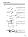
Follow the instructions below when connecting the power cord.
24V
100V
DC
AC
+
L
-
N
Black
White
FG
FG
24V
DC
Green
100V
AC
+
L
-
N
Black Black
White White
FG
1. Make sure the POWER switch is
OFF. Then, remove the power input terminals’ transparent cover,
located on the rear panel of the PL.
FG
Green Green
2. Loosen and remove the middle three
screws from the terminal board. Align
crimp terminals to each screw hole, and
tighten the screws.
• Crimp Terminal Types :
V1.25-3, by J.S.T. or equivalent (JIS
standard part number : RAV1.25-3)
^
Max. 6.0 mm
24V
100V
DC
AC
+
L
-
N
FG
^
• Crimp terminals must be the same
as shown below.
φ 3.2 mm or larger
^
• The colors in the figure above are
for the cable which came with the
PL.
3. Reattach the protective transparent
cover.
FG
Transparent
cover
PL-5700 Series User’s Manual
4-6
Installation and Wiring
2
Cautions: 100V PL-5700T*/S*/L* Units
When connecting power to the 100V PL Unit’s AC power terminals, please be aware of the following:
Constant
voltage
transformer
Insulating
transformer
Twisted-pair
cable
PL
FG
For information about the specified
voltage, refer to “2-1 General
Specifications”
Twisted-pair
cable
PL
FG
100V AC
PL
PL power
source
Main power
source
I/O power
source
• If voltage fluctuations are expected to vary beyond the specified range, connect a constant
voltage transformer.
I/O
device
• Use a low-noise power supply both between the lines and between the PL and its
ground. If there is still excess noise, connect an insulating transformer (noise-prevention type) .
Be sure any constant or insulating
transformer used has a capacity of 200V
AC or more.
• Wire the power cords of the 100V PL, I/O
devices, and power supply devices separately.
Main power
source
200V AC
PL
PL power
source T1
T2
I/O power
source
I/O
device
I/O
device
• To improve noise immunity, it is recommended to attach a ferrite core to the power
cord.
• Isolate the main circuit (high voltage, large
current) line, I/O signal lines, and power
cord, and do not bind or group them together.
Power
device
Main circuit
power source
Twisted-pair
cable
• To prevent damage from lightning, connect a
lightning surge absorber.
PL
AC
FG
E1
Lightning surge absorber
• Ground the lightning surge absorber (E1)
and the PL (E2) separately.
• Select a lightning surge absorber which will
not exceed the allowable circuit voltage, even
when the voltage rises to the maximum.
PL-5700 Series User’s Manual
4-7
Installation and Wiring
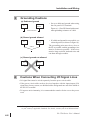
3
Grounding Cautions
(a) Dedicated ground
Other
device
PL
• Set up a dedicated ground when using
the rear panel’s FG terminal.
Figure (a) = Class III Ground with a maximum grounding resistance of 100Ω.
Class III Ground
(b) Shared ground allowed
Other
device
PL
• If a dedicated ground is not possible, use
a shared ground, as shown in figure (b).
The grounding point must be as close to
the PL as possible, and the grounding wires
must be as short as possible. If the wires
must be long, use thick, insulated wires and
run them through conduits.
Class 3
(c) Shared ground not allowed
PL
4
Other
device
Cautions When Connecting I/O Signal Lines
• I/O signal lines must be wired separately from the power circuit cable.
• If the power circuit cable needs to be wired together with the input/output (I/O)
signal lines for any reason, use shielded cables and ground one end of the shield to
the PL’s FG terminal.
• To improve noise immunity, it is recommended to attach a ferrite core to the power
cord.
*1 Use a grounding resistance of less than 100Ω and a 2mm2 or greater thickness wire,
or your country’s applicable standard. For details, contact your local GP distributor.
PL-5700 Series User’s Manual
4-8
Chapter
5
5-1 Setup Procedures
5-2 System Parameters
System Setup
This chapter describes how to configure the system before operating the PL, and
lists the system parameters.
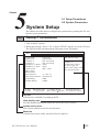
5-1 Setup Procedures
1. Turn on the PL’s power.
2. When the message “Press <F2> to Enter SETUP” appears, press the [F2] key.
The SETUP utility will start and the following screen will appear.
Main
PhoenixBIOS Setup - Copyright 1985-95 Phoenix Technologies Ltd.
Advanced
Power
Exit
System Time:
System Date:
Diskette A:
Diskette B:
IDE Adapter 0 Master
IDE Adapter 0 Slave
Video System
Memory Cache
Memory Shadow
Boot sequence:
Back Light/Contnast:
[15:00:00]
[08/25/1995]
[Not Installed]
[Not Installed]
(None)
(None)
[EGA / VGA]
System Memory:
Extended Memory:
640KB
7168KB
F1 Help
ESC Exit
↑ ↓
←→
Item Specific Help
Attempts to
automatically detect
the drive type for
drives that comply with
ANSI specifications.
[C: then A:]
[Standard/4]
Select Item
Select Menu
-/+ Change Values
Enter Select Sub-Menu
F9 Setup Defaults
F10 Previous Values
Key list
Lists the keys available for setting up the PL.
Help display area
Provides detailed information about the item at the cursor position.
System set-up area
Lists system parameters for the selected menu.
Menu bar
Contains four menus: Main, Advanced, Power and Exit.
PL-5700 Series User’s Manual
5-1
System Set-up
The keys available for operating the SETUP utility are as follows.
[F1]
: Provides information related to the entire SETUP utility. Use the [↑] or
[↓] key to scroll the display.
[↑] [↓] : Moves the cursor to select an item from the menu.
[-][+] : Changes the value at the cursor position.
[F9]
: Returns the parameters listed in the system setup area to the default values.
[ESC] : Goes to the Exit menu.
[←][→] : Changes the menu screens.
[Enter] : If the [Enter] key is pressed while the cursor is placed on the item marked
with a black delta ( ), a submenu will appear. Pressing the [ESC] key
on the submenu will return you to the main menu.
[F10] : Returns the parameters listed in the system setup area to the CMOS’s
current values.
5-2
PL-5700 Series User’s Manual
System Set-up
5-2
1
System Parameters
Main
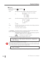
System Time
Enter the hour, minute, and second values, in the order and ranges given below.
Hour
: 00 - 23
Minute : 00 - 59
Second : 00 - 59
Use the [Enter] key to place the cursor on an item you want to change, and enter
the desired value.
System Date
Enter the month, day, and year, in the order and ranges given below.
Month
: 01 - 12
Day : 01 -31
Year : four digits
Use the [Enter] key to place the cursor on an item you want to change, and enter
the desired value.
Diskette A
Diskette B
These parameters are required when one or two floppy disk drives are connected.
Possible options are as follows.
Not Installed
360kB, 5 1/4
1.2 MB, 5 1/4
720kB, 3 1/2
1.44 MB, 3 1/2 *
2.88 MB, 3 1/2
If no floppy disk drive is installed, select the “Not Installed” option. Selecting other options may
cause an error.
* If the optional flash ROM board is installed, set this parameter to “1.44 MB, 3 1/2.”
PL-5700 Series User’s Manual
5-3
System Set-up
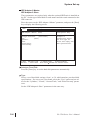
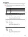
IDE Adapter 0 Master
IDE Adapter 0 Slave
These parameters are required only when the optional HDD unit is installed on
the PL. Set the type of hard disk for each master and slave unit connected to the
IDE connector.
Place the cursor on the “IDE Adapter 0 Master” parameter, and press the [Enter]
key to display the following screen.
PhoenixBIOS Setup - Copyright 1985-95 Phoenix Technologies Ltd.
Main
Advanced
Power
Exit
IDE Adapter 0 Master
(None)
Autotype Fixed Disk:
[Press Enter]
Type:
[None]
Cylinders:
Heads:
Sectors/Track:
Write Precomp:
F1 Help
ESC Exit
↑ ↓
Select Item
Menu
←←→→Select
Item Specific Help
Attempts to
automatically detect
the drive type for
drives that comply with
ANSI specifications.
-/+ Change Values
F9 Setup Defaults
Enter Select Sub-Menu F10 Previous Values
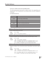
Autotype Fixed Disk
Press the [Enter] key to set the hard disk parameters automatically.
Type
Select a set of hard disk settings, from 1 to 39, which matches your hard disk
specifications. If a correct set is not found, select the “User” option and set values for the “Cylinders,” “Heads,” “Sectors/Track,” and “Write Precomp” parameters.
Set the “IDE Adapter 0 Slave” parameters in the same way.
5-4
PL-5700 Series User’s Manual
System Set-up
Video System
Set the type of the display.
You must select the “EGA/VGA” option for the PL to operate correctly.
Memory Cache
Press the Enter key to set the cache memory parameters.
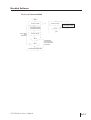
Memory Shadow
Memory shadow copies information from the ROM BIOS to RAM to improve
the PL’s performance.
System shadow
This parameter is fixed as “Enabled,” since information in the system BIOS must
be copied to RAM.
Video shadow
Selects whether or not information in the video BIOS is copied to RAM.
Shadow Memory Regions
Selects the starting address to which the BIOS information is copied to. This
parameter is required when installing a board containing the extended BIOS in
the extended ROM area.
Boot sequence
Selects the drive from which you want to start the OS.
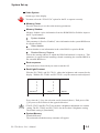
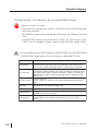
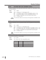
BackLight/Contrast
With the PL-5700L1 and PL-5701L1, adjust the brightness and contrast for the
display. With the PL-5700S1 and PL-5701S1, only the contrast can be adjusted.
Standard/ 0
1
2
3
4
5
6
Standard/ 7
S ta ndard brightnes s
B right/ 0
1
2
3
4
5
6
B right/ 7
Darker
B righter
High brightnes s
Every time the [+] key, the selection scrolls forward (down). Each press of the
[-] key moves the selection in the opposite direction.
• The PL-5700T1 and PL-5701T1 do not have a brightness adjustment or a contrast
setting. The PL-5700S1 and PL-5701S1 also do not have a brightness setting.
The default setting is [Standard/4].
System Memory
Extended Memory
The main and extended memory amounts will appear.
PL-5700 Series User’s Manual
5-5
System Set-up
2
Advanced
Select the “Advanced” menu from the menu bar to display the following window.
PhoenixBIOS Setup - Copyright 1985-95 Phoenix Technologies Ltd.
Main
Advanced
Power
Exit
Warning!
Setting items on this menu to incorrect values
may cause your system to malfunction.
Item Specific Help
Integrated Peripherals
Advanced Chipset Control
Large Disk Access Mode: [DOS]
↑ ↓ Select Item
F1 Help
-/+ Change Values F9 Setup Defaults
←→
Exit ← → Select
Menu Enter Select Sub-Menu F10 Previous Values
ESC
Integrated Peripherals
Align the cursor with this item and press the [Enter] key to set advanced parameters for the chipset.
Normally, use the default value.
PhoenixBIOS Setup - Copyright 1985-95 Phoenix Technologies Ltd.
Main
Advanced
Power
Exit
Integrated Peripherals
COM 1 port :
COM 2 port :
LPT port
:
LPT Mode
:
Diskette controller:
IDE adapter:
[3F8, IRQ 4]
[2F8, IRQ 3]
[3BC, IRQ 7]
[Output Only]
[Enabled]
[Enabled]
Item Specific Help
Set COM port address.
↑ ↓ Select Item
F1 Help
-/+ Change Values F9 Setup Defaults
←→
Exit ← → Select
Menu Enter Select Sub-Menu F10 Previous Values
5-6
ESC
PL-5700 Series User’s Manual
System Set-up
COM 1 Port
This setting designates the value used for the PL’s COM 1 port address. The
selections include [Disabled], [3F8/IRQ4], [2F8/IRQ3], [2E8/IRQ3] and [Auto].
The factory setting is [3F8/IRQ4] and is recommended.
COM 2 Port
This setting designates the value used for the PL’s COM 1 port address. The
selections include [Disabled], [2F8/IRQ3], [3E8/IRQ4], [2E8/IRQ3] and [Auto].
The factory setting is [2F8/IRQ3] and is recommended.
LPT Port
This setting designates the value used for the PL’s LPT port address. The selections include [Disabled], [3BC/IRQ7], [378/IRQ7], or [278/IRQ5]. When using
any setting other than [Disabled], the LPT mode setting must be changed to [Outout
Only] or [Bi-Directional]. The factory setting is [3BC/IRQ7] and is recommended.
LPT Mode
This setting designates the mode of the PL’s PLT port address. The selections
include [Output Only] (unidirectional), and [Bi-Directional] (both directions).
The factory setting is [Output Only] and is recommended. When the LPT Port is
set to [Disabled], this setting is also disabled.
Diskette controller
The selections include [Disabled] or [Enabled]. The factory setting is [Enabled]
and is recommended.
IDE adapter
The selections include [Disabled] or [Enabled]. The factory setting is [Enabled]
and is recommended.
PL-5700 Series User’s Manual
5-7
System Set-up
Advanced Chipset Control
Press the [Enter] key to set advanced parameters for the chipset.
Normally, use the default value.
System Information List and Default Settings
System Info rma tion
ATCLK Selection
Multiple ALE
xtra bus wait states
Master mode byte swap
Parity check
Hidden refresh
Slow reflesh
Read wait states
Write wait states
Turbo Mode
AT Clock Mode
DMA Clock
8Bit DMA Waits
16 Bit DMA Waits
DMA MEMR# Signal
IO Wait State
Default v alues
C LK /4
E nabled
1
Dis abed
Dis abed
Dis abed
Dis abed
4-3-3-3 1Wait
1
E nabled
S ync
S ys clock/2
1
1
Normal
4
Large Disk Access Mode
If your hard disk contains 528 MB or more of memory, select the type of OS to be
used.
DOS : MS-DOS
Other : OS other than MS-DOS
5-8
PL-5700 Series User’s Manual
System Set-up
3
Power
Select the “Power” menu from the menu bar to display the following screen.
Fixed Disk Timeout (Time before Standby)
Set the number of minutes to elapse from when the PL last accesses the hard disk to
when the hard disk motor stops.
Every time the [+] key is pressed, the selections are highlighted in the following
order: “Disabled,”→“1min,”→“2min,” →“3min,”→“4min,”→“5min,”→“10min,”→“16min.”
Each press of the [-] key moves the selection in the opposite direction.
PhoenixBIOS Setup - Copyright 1985-95 Phoenix Technologies Ltd.
Main
Advanced
Power
Exit
Fixed Disk Timeout: [Disabled]
Item Specific Help
Period of fixed disk
inactivity required
before Standby.
F1 Help
ESC Exit
PL-5700 Series User’s Manual
↑ ↓
Select Item
Menu
←←→→Select
-/+ Change Values
Enter Select Sub-Menu
F9 Setup Defaults
F10 Previous Values
5-9
System Set-up
4
Exit
Select the “Exit” menu from the menu bar to display the following screen.
PhoenixBIOS Setup - Copyright 1985-95 Phoenix Technologies Ltd. Main
Advanced
Power
Exit
Save Changes & Exit
Discard Changes & Exit
Get Default Values
Load Previous Values
Save Changes
F1 Help
ESC Exit
↑ ↓
Item Specific Help
Exit after writing
all
changed SETUP item
values to CMOS.
Select Item
-/+ Change Values F9 Setup Defaults
Menu Enter Select Sub-Menu F10 Previous Values
←←
→→Select
Save Changes & Exit
Select this option to store your changes in the CMOS and reset the PL.
Discard Changes & Exit
Select this option to abort your changes and reset the PL.
Get Default Values
Select this option to return the parameter settings to the default.
Load Previous Values
Select this option to load the parameter settings from the CMOS.
Save Changes
Select this option to store your changes in the CMOS.
5-10
PL-5700 Series User’s Manual
Chapter
6
6-1 File List
6-2 Touch Panel Input File
6-3 Other Files
Bundled Software
The PL comes with programs not supplied in the standard MS-DOS or Windows® OS,
including touch panel input programs. This chapter explains the types of software bundled
with this product, hereafter refered to as “this software.”
6-1 File List
• Digital does not guarantee this software will work with OSs other than those listed here.
File name
Des cription
C on ta in s d e tai l ed in fo rm at i o n o n i nc lud e d f i l es a n d u p- to -d at e
README.TXT n ew s. Re ad th is fi l e b e fo re us in g a n y o f t he bu n dl ed
s of t wa re .
The following software runs on Windows® 3.1/3.11 and/or Windows® 95.
File name
Des cription
WCONTSET.E- C ON TS ET uti l i ty ' s e xp l a na ti o n a n d u p d a te f o r
XE
W in d o w s ® 3 . 1 /W in d o w s ® 9 5
B LS AV ER .S CR
T un s o f f t h e b a c k l i g h t. C on t a i n s S cr e e n S av e r f o r
W in d o w s ® 3 .1 a n d S cr e e n S av e r f o r W in d o w s ® 9 5 .
• WCONTSET.EXE cannot be used with the PL-5700T1, PL-5700T1-24VC, or PL5701T1.
Also, the brightness setting is unused on the PL5700S1 and PL-5701S1.
The following software runs only on Windows® 3.1 or 3.11.
File name
Des cription
U ti l i t y f o r u s e wi t h W i n d o w s 3 . 1 /3 . 1 1 s of t w a r e . Is us ed
to r e c o r d a nd a u t o m a te k e ys tr o k e s , w h i c h a r e a c ti v a te d
FUNCKEY.EXE
v i a to u c hi n g u s er d e fi n e d f u n c ti o n k e y s a ro u n d th e
p e r i p h e r y o f t h e T ou c h P a ne l.
Panel Computer PL-5700 Series User’s Manual
6-1
Bundled Software
The following PL-5700 software is for use with MS-DOS systems
• Must be version 3.21 or later.
• Digital does not guarantee this software will work with any OS other than those
previously mentioned.
• This software is made for use with MS-DOS. Do not use it in a Windows® environment.
• CONTSET.EXE cannot be used with the PL-5700T1, PL-5700T1-24VC or PL5701T1. Also, the brightness setting is ignored on the PL5700S1 and PL-5701S1.
• For an explanation of the EXTCOM.SYS, CONTSET.EXE, WCONTSET.EXE and
FUNCKEY.EXE applications, refer to their respective README.TXT file.
File name
6-2
Des cription
PLATPH.EXE
Touch panel handler
C onverts input from the touch panel in line with dis play panel res olution (640 x
480). It is also compatible with Digital P anel Computers of the PL-386 family.
P LC ALIB .E XE
Touch panel data c alibration
B y touching the specified pos ition on the panel, the difference between the logic
value and measured value is corrected. Furthermore, us ing the PLATPH.E XE
application, it is pos s ible to create files with data bas ed on calibration res ults
obtained here.
K EYEM_P L.EX E
K eyboard emulator
Dis plays a picture of a keyboard on the s creen, enabling input from the touch
panel.
DIS P.EX E
Dis play On/Off program
Turns the dis play, including the backlight, on/off.
FANALAR M.EX E
Detects alarms in the C PU cooling fan.
E XTCOM.SYS
C OM port driver (reception interrupt acknowledge). For details , s ee the
R EADME.TX T file on the same disk.
C ONTS ET.E XE
F or setti ng contras t with the PL-5700S1 and P L-5701S 1 when equipped with the
backlight brightness and contras t control utility for the P L-5700L1 and P L5701L1.
PL-5700 Series User’s Manual
Bundled Software
6-2 Touch Panel Input File
1
PLATPH.EXE (Touch Panel Handler)
With an analog touch panel, input is recognized within a 1024 x 1024 pixel area, with
the lower left-hand corner as the coordinate origin point. However, most display panels use the upper left-hand corner as the origin point and have a resolution of 640 x
480 pixels. Consequently, depending on the conditions of use, the touch panel position and display position may not be the same. Here, the PLATPH.EXE application
solves this problem by converting input from the touch panel into the corresponding
display panel coordinates, allowing the use of application programs which use absolute coordinate input or area input from a touch panel.
The relationship between touch panel coordinates and display coordinates is as follows.
Function area
Virtual coordinates
(0, -40)
Touch panel
coordinates
(1024, 1024)
Display coordinates
(0, 0)
Display coordinates
(639,479)
Touch panel
coordinates
(0, 0)
Function area
Virtual coordinates
(639, 519)
Relationship between touch panel coordinates and display coordinates when using
the PL-386 Series compatibility mode
To ensure compatibility with 16 x 14 (31 x 27 by double precision) touch panels used
on the Digital PL-386 family of Panel Computers, the TPH.EXE (PL-386 command)
function can be used as is.
The relationship between touch panel coordinates and display coordinates is as follows.
(0,0) (1,1) (2,1)
(0,1)
(0,2)
Touch panel coordinates in
PL-386 family compatibility mode
Input coordinate range
X = 0 ~ 30
Display area in
640 x 480 mode
(30,24)
(30,25)
Y = 0 ~ 26
(30,26)
: Touch panel effective area
The touch panel handler cannot be used in conjunction with the TT-WIN mouse
emulator on Windows® . Cancel the resident program before starting up Windows®.
PL-5700 Series User’s Manual
6-3
Bundled Software
Start-up
PLATPH [Parameter] [↵] or PLATPH -r [↵]
* Parameters
-a<n>
Specifies the I/O base address of the touch panel’s SIO port.
n=
-q<n>
10
Hexadecimal, Default: 2e8 (COM4)
3f8 (COM1)
n 2f8 (COM2)
3e8 (COM3)
2e8 (COM4)
Specifies the interrupt level (IRQ) of the touch panel’s SIO port.
11
(COM4)
Default: 10 (COM4)
n= 4
(COM1)
3
(COM2)
(COM3)
-i<n>
Sets the software interrupt vector number when calling up functions.
Hexadecimal, Default: n=59
-r
Cancels the resident command.
-c <path name> Specifies the data file containing the calibrated value obtained from
the PLCALIB.EXE application (touch panel data calibration).
When defaulted to, the PLATPH.CAL of the current directory is specified.
∗ Example platph -a2e8 -q10 -cc:\platph.cal
Normally, only “platph” is needed.
At startup, the following message will appear on the screen.
Analog Touch Panel Handler PLATPH.EXE Version X.XX
Copyright (c) 199X Digital Electronics Corporation
Stay resident.
After startup, these commands reside in memory.
• If an error is generated because, for example, there is no file created by the
PLCALIB.EXE application, the following message appears on the screen, and the
system will start up in a mode that does not calibrate data.
WARNING!! Can’t open CAL file.
Stay resident.
• Unless properly calibrated, the display and touch panel input positions may not be the same.
6-4
PL-5700 Series User’s Manual
Bundled Software
Functions
PLATPH.EXE calls up functions using a software interrupt (default: INT 59h).
For information on functions in the PL-386 compatibility mode, see pages 6-7 to 6-10.
INT 59h Function List
Function code
Description
8100h
Touch panel input (unrestricted wait)
8101h
Touch panel input (???auto restore???)
8102h
Touch panel non-destructive input
0200h
Input buffer clear
8500h
Touch panel status detection
FE00h
Reside check
8100h
Touch panel input (unrestricted wait)
Returns coordinates of the area/position touched. Waits until data is input.
Input
AX = 8100h
Output
AH = 0: Successfully completed
BX = Y coordinate in 640 x 480 mode (-40 - 519)
DX = X coordinate in 640 x 480 mode (0 - 639)
CX = Number of valid input buffers on touch panel
8101h
Touch panel input (immediate restore)
Returns coordinates of the area/position touched. Immediately restored if nothing is entered.
Input
AX = 8101h
Output
AH = 0: Input ON
1: Input OFF
BX = Y coordinate in 640 x 480 mode (-40 - 519)
DX = X coordinate in 640 x 480 mode (0 - 639)
CX = Number of valid input buffers on analog touch panel
8102h
Touch panel non-destructive input
Returns coordinates of the area/position touched. Does not update the touch panel input
buffer.
Input
AX = 8102h
Output
AH = 0: Input on
1: Input off
BX = Y coordinate in 640 x 480 mode (-40 - 519)
DX = X coordinate in 640 x 480 mode (0 - 639)
CX = Number of valid input buffers on analog touch panel
PL-5700 Series User’s Manual
6-5
Bundled Software
0200h
Input buffer clear
Clears touch panel input buffers.
Input
AX = 0200h
Output
AH = 0: Successfully completed
8500h
Touch panel status detection
Returns touch panel status
Input
AX = 8500h
Output
AH = Status in 640 x 480 mode
Bit 1
B it 0
Des cription
0
0
Area pres s ed
0
1
Unchanged
1
0
Not available
1
1
Area released
* For an explanation on how to use the function, see “function 500h.”
FE00h
Resident check
When the PLATPH.EXE application resides in memory, returns a fixed message and
version.
Output
AH = 0: Successfully completed
BL = ‘Y’
Bit15
BH = ‘B’
1000
CX = Version No.
PLATPH.EXE
ID code
^
6-6
^
Carry = Clear
00
^
AX = FE00h
^
Input
Version No.
PL-5700 Series User’s Manual
Bundled Software
Functions available in PL-386 Compatibility Mode
The following data details the functions available in the PL-386 compatibility mode
(when the user’s PL-386 application is used without further conversion, updating or
formatting).
INT 59h Function List
Func tion code
Des cription
0000h
Touch panel initialization
0100h
Touch panel input (unres tricted wait)
0101h
Touch panel input (? ? ? auto restore? ? ? )
0102h
Touch panel non-des tructive input
0300h
Coordinate code regis ter
0400h
Coordinate code input (unres tricted wait)
0401h
Coordinate code input (? ? ? auto restore? ? ? )
0402h
Coordinate code non-des tructive input
0500h
Touch panel s tatus detection
0000h
Touch panel initialization
Same as 0200h (Input buffer clear)
Input
AX = 0000h
Output
AH = 0: Successfully completed
0100h
Touch panel input (unrestricted wait)
Returns coordinates of the area/position touched. Waits until input is made.
Input
AX = 0100h
Output
AH = 0: Successfully completed
BH = Y coordinate range in PL-386 compatibility mode (0 - 26)
BL = X coordinate range in PL-386 compatibility mode (0 - 30)
CX = Number of valid data sets in touch panel input buffers
0101h
Touch panel input (immediate restore)
Returns coordinates of the area/position touched. Immediately restored after input is
made.
Input
AX = 0101h
Output
AH = 0: Input on (“1” when input is off)
BH = Y coordinate range in PL-386 compatibility mode (0 - 26)
BL = X coordinate range in PL-386 compatibility mode (0 - 30)
CX = Number of valid data sets in touch panel input buffers
PL-5700 Series User’s Manual
6-7
Bundled Software
0102h
Touch panel non-destructive input
Returns coordinates of the area/position touched. Does not update touch panel input buffer.
Input
AX =
Output
AH =
0: Input present (No input = 1)
BH =
Y coordinate range in PL-386 compatibility mode (0 - 26)
BL =X coordinate range in PL-386 compatibility mode (0 - 30)
CX =
Number of valid data sets in touch panel input buffers
0300h
0102h
Coordinate code register
Registers code corresponding to the display coordinates.
Input
AX = 0300h
ES = Segment from coordinate code management table
DI = Offset from coordinate code management table
Output
AH = 0: Successfully completed
∗ Relationship between coordinate code management table and coordinate code
ES : DI
Coordinate code
management table
Coordinate & Coordinate code
Coordinate & Coordinate code
Coordinate & Coordinate code
∗ Coordinate code management table setup
The coordinate code management table manages positions of multiple coordinate code lists.
Number (n) of registered coordinate code lists
Offset of 1st coordinate code lis t
S egment of 1s t coordinate code lis t
~
~
Offset of 2nd coordinate code lis t
S egment of 2nd coordinate code lis t
:
Offset of nth coordinate code lis t
S egment of nth coordinate code lis t
6-8
PL-5700 Series User’s Manual
Bundled Software
∗ Coordinate code list setup
The coordinate code list determines which code is returned when the touch panel is
pressed in a specific area.
These coordinates specify the display coordinates.
Number (n) of registered coordinate codes
Dis play coordinate des ignation mode
Left s ide X coordinate of 1st area (X 1)
Top side X coordinate of 1st area (Y1)
~
R ight side X coordinate of 1st area (X 2)
~
B otto m side X coordinate of 1st area (Y2)
Coordinate code of 1st area (code)
:
Left s ide X coordinate of nth area (X 1)
Top side X coordinate of nth area (Y1)
R ight side X coordinate of nth area (X 2)
B otto m side X coordinate of nth area (Y2)
Coordinate code of nth area (code)
0400h
Coordinate code input (unrestricted wait)
Returns coordinates of the area/position touched and coordinate code. Waits until data is entered.
Input
AX =
0400h
Output
AH =
0: Successfully completed
BH= Y coordinate range in PL-386 compatibility mode (0 - 26)
BL = X coordinate range in PL-386 compatibility mode (0 - 30)
CX= Number of valid data sets in touch panel input buffers
DX= Coordinate code
To use function 0400h, it is necessary to first register the coordinate codes.
PL-5700 Series User’s Manual
6-9
Bundled Software
0401h
Coordinate code input (immediate restore)
Returns coordinates of the area/position touched and coordinate code. Immediately restored
after data is entered.
Input
AX= 0401h
Output
AH=
BH=
BL =
CX=
DX=
0: Input on (“1” when input is off)
Y coordinate range in PL-386 compatibility mode (0 - 26)
X coordinate range in PL-386 compatibility mode (0 - 30)
Number of valid data sets in touch panel input buffers
Coordinate code
To use function 0401h, it is necessary to first register the coordinate codes.
0402h
Coordinate code non-destructive input
Returns coordinates of the area/position touched. Does not update the touch panel input
buffer.
Input
AX= 0402h
Output
AH=
BH=
BL =
CX=
DX=
0: Input on (“1” when input is off)
Y coordinate range in PL-386 family compatibility mode (0 - 26)
X coordinate range in PL-386 family compatibility mode (0 - 30)
Number of valid data sets in input buffers on touch panel
Coordinate code
To use function 0402h, it is necessary to first register the coordinate codes.
0500h
Touch panel status detection
Returns the touch panel’s current status
6-10
Input
AX = 0500h
Output
AH = Status in PL-386 compatibility mode
Bit 1
B it 0
Des cription
0
0
Area pres s ed
0
1
Unchanged
1
0
Not available
1
1
Area released
PL-5700 Series User’s Manual
Bundled Software
How to use function 0500h
Start
or
Function 0100h
Function 0101h
Processing until touch
panel area is released
Input?
Processing until touch
panel area is pressed
No
Yes
Function 0500h
Touch panel
area
held down
Bit 0
0
1
0
Bit 1
Coordinates
changed while
touch panel area
is pressed.
1
To next touch panel input
PL-5700 Series User’s Manual
6-11
Bundled Software
2
PLCALIB.EXE (Touch Panel Data Calibration)
By touching the specified position (upper left-hand corner or lower right-hand corner) on the panel, the difference between the screen’s logical value and its measured
value is corrected. Furthermore, it is possible to create files with data based on calibration results obtained here, to be used with the PLATPH.EXE application (Touch
Panel Handler).
Start-up
PLCALIB [Parameter] [↵]
∗ Parameter
-a<n>
Specifies the I/O base address of the touch panel’s SIO port.
Hexadecimal, Default: 2e8 (COM4)
n=
3f8
(COM1)
n
2f8
(COM2)
3e8
(COM3)
2e8
(COM4)
-q<n>
Specifies the interrupt level (IRQ) of the touch panel’s SIO port.
Default: 10 (COM4)
n=
4
(COM1)
3
(COM2)
11
(COM3)
10
(COM4)
-c <path name> Specifies the data file containing the calibrated value obtained from
the PLCALIB.EXE application (touch panel data calibration).
When defaulted to, the PLATPH.CAL of the current directory is specified.
∗ Example platph -a2e8 -q10 -cc:\platph.cal
Normally, only “platph” is needed.
Operation
Analog Touch Panel Calibration PLCALIB.EXE Version X.XX
Copyright(c) 199X Digital Electronics Corporation
Calibration Mode
Touch upper left and lower right cornner of the screen.
[Enter] : Go to test mode.
[Esc] : Terminate program.
Upper left Lower right
(0000,0000) (0000,0000)
6-12
c When the PLCALIB.EXE application
is opened up, the message shown at
the left will appear on the screen, and
two points will light up, in both the
upper left-hand and lower right-hand
corners.
PL-5700 Series User’s Manual
Bundled Software
Analog Touch Panel Calibration PLCALIB.EXE Version X.XX
Copyright (c) 199X Digital Electronics Corporation
Calibration Mode
Touch upper left and lower right corner of the screen.
[Enter : Go to test mode.
[Esc] : Terminate program.
Upper left Lower right
(0039.0026) (0997.0988)
The measured value is
displayed on the screen.
Terminate program without saving calibration data?(Y/N)
Analog Touch Panel Calibration PLCALIB.EXE Version X.XX
Copyright (c) 199X Digital Electronics Corporation
Test Mode
[Enter] : Save calibration data and Exit.
[Esc] : Return to calibration mode.
d Touch each point, in the order it appears.
• Do not touch both points simultaneously.
• Touch the panel exactly on the lit up areas.
• The measured value is redisplayed if you
touch the panel again.
The difference between the logic value and the
measured value is obtained.
• To quit programming, press the [Esc] key.
Then, when the message shown on the left
appears, press the [Y] key. The program
will end without saving data. Here, pressing the [N] key will return you to the calibration mode.
e Start up the “Test Mode” with the [↵
↵] key.
This mode tests the calibrated value to determine if it is correct or not.
The perimeter is OK if it is drawn along the path
you traced by finger. Otherwise, return to the
“Calibration Mode” and touch the lit up areas
again.
• You can return to the “Calibration Mode”
with the [Esc] key.
Calibration data name? PLATPH.CAL_
f If test results are OK, press the [Enter] key.
When the message shown at the left appears,
input the data file name and press the [↵] key.
• When specifying the data file name for the parameter (-C=[path name]) at the
PLCALIB.EXE start-up, the program ends
without displaying the message shown on the
left.
PL-5700 Series User’s Manual
6-13
Bundled Software
6-3 Other Files
1
DISP.EXE (Display ON/OFF Program)
*MS-DOS® only
This application turns the display, including the backlight, ON or OFF.
Start-up
DISP ON [↵,] or DISP OFF [↵]
The command’s execution result is set on the MS-DOS ERROR LEVEL. ERROR LEVELS are as follows.
ERROR LEVEL
0
1
-1
2
DESCRIPTION
Successfully completed
Expansion BIOS (INT 5Fh) error
Other (command parameter, etc.) error
FANALARM.EXE (CPU Cooling Fan Alarm Detection Program)
*MS-DOS® /Windows® 3.1only
This application sounds a buzzer when the CPU cooling fan stops.
Start-up
FANALARM [↵] or FANALARM -r [↵]
∗ Parameters
-r
Cancels the resident command.
If the fan stops and the buzzer sounds, promptly save any data not yet saved,
quit all current applications, and check the fan.
• There is no function for silencing the buzzer. Only turning the power OFF will turn it off.
• In a multitasking environment such as Windows®, the buzzer may be turned off by
another task.
3
BLSAVER.SCR
(
(Windows®3.1 Screen Saver/
Windows®95 Screen Saver)
This application turns off the backlight.
How to use
1) Copy the BLSAVER.SCR application into the directory where installed Windows®
3.1/Windows® 95.
2) Select “Control Panel” >> “Display” >> “Screen Saver” >> “Back light OFF”.
3) Set the “Wait” value and close the Control Panel.
If no input is made from the keyboard, mouse or touch panel within the set amount
of time, the backlight will turn off. The backlight turns back on when input is
made from the keyboard, mouse or touch panel.
6-14
PL-5700 Series User’s Manual
Maintenance and Inspection
Chapter
7
7-1 Cleaning the Display
7-2 Replacing the 100V Unit’s Backlight
7-3 Periodic Check
Maintenance and Inspection
This chapter describes how to maintain the PL to ensure more comfortable use.
7-1 Cleaning the Display
When the display surface or frame become
dirty, use a soft cloth moistened with neutral detergent to wipe away dust or stains.
Neutral
detergent
Protective panel
Display
Do not clean the unit with thinner, organic
solvents, or strong acids.
Thinner
Organic solvent
Strong acid
Do not use sharp or hard objects, such as a
mechanical pencil or screwdriver, to push
on the display. This could damage the unit.
Protection sheet
Use the screen protection sheet when using the unit in especially dirty or dusty areas.
PL-5700 Series User’s Manual
7-1
Maintenance and Inspection
7-2 Replacing the 100V Unit’s Backlight
If the 100V unit’s display becomes dark while running the PL, there may be a
problem with the backlight. If a problem is found or if the backlight is burnt out,
you will need to replace it with a new one.
With the PL-570*T1 and PL-570*S1, you can replace the backlight by yourself. However, if your model is the PL-570*L1 or the PL-570T1-24VC, you will need to ask a
Digital service person to replace the backlight. Please contact your nearest Digital
Service Center. Also, when using the PL-570*T1 or PL-570*S1, replace the backlight following the instructions below. The part number of the replacement backlight
is “GP570-BL00-MS.”
WARNING
Only a Digital serviceman should replace the 24V AC unit’s backlight.
To avoid electric hazards and burns, turn OFF the power to the PL before replacing the
backlight. Also, be sure to wear gloves when handling the backlight.
Be careful not to drop or break the old backlight.
screw
Backlight
replacement
cover
1. Loosen the screw on the backlight recover on the rear panel of the PL, to remove the cover.
2. Unplug the backlight’s connector, and remove the screw which holds the backlight in place. Be careful not to drop this
screw inside the PL.
Backlight
Connector
plug,
To un is way
pull th
3. Slide the replacement backlight into the
PL, secure it in place with the attachment
screw, and re-attach the connector.
4. Replace the backlight’s cover and tighten
its attachment screw. Be careful not to
pinch the connector lines between the PL
body and this cover.
PL-5700 Series User’s Manual
7-2
Maintenance and Inspection
7-3 Periodic Check
Check the PL periodically to ensure it is in good working condition.
• Ambient environment check points
Is the ambient temperature within the specified range?
0 to 45°C
0 to 40°C
for the PL-5700T1 andPL-5701T1
for the PL-5700S1, PL-5700T1-24VC, PL-5701S1, PL-5700L1,
and PL-5701L1
Is the ambient humidity within the specified range (30 to 85 %RH) ?
Is the atmosphere free of corrosive gas ?
• Electrical specifications check
Is the voltage adequate (85 to 132 V AC, 50/60 Hz for the 100V AC units) ?
(19.2V to 28.8V DC, 50/60 Hz for the 24V DC unit) ?
• Installation check points
Is the connection cable firmly connected (not loose) ?
Are any bolts or screws loose ?
Are there any flaws or tears in the moisture resistant packing ?
• Display check
Is the display bright enough ?
PL-5700 Series User’s Manual
7-3
Maintenance and Inspection
MEMO
PL-5700 Series User’s Manual
7-4
Chapter
A
1. Hardware Configuration
2. Serial Communications
3. Printer Cable Connections
ppendix
4. Touch Panel Handler Sample
Program
5. BIOS Lists
1
Hardware Configuration
1
I/O Mapping
Address
AT s ys tem device
0000H- 001F H
DMA controller (8237)
0020H- 002FH
Interrupt controller (8259A)
0040H- 005FH
System timer (8254)
0060H- 006FH
Keyboard (H8/3332)
0070H- 007FH
Real-time clock, NMI mask
0080H- 009FH
DMA bank regis ter
00A0H - 00BF H
Interrupt controller (8259A)
S ys tem-specific device
00C0H - 00DF H DMA controller 2 (8237)
00F0H - 00F F H
Numeric data proces s or
0103H
Used by main board
016CH - 016FH
Us ed by main board
F la sh ROM board bank
0170H- 0171H
Memory card interface
Memory card interface memory bank
01F 0H - 01F F H
Hard dis k (IDE)
0200H- 0207H
G ame I/O *1
02E8H - 02EF H
S erial port 4 (C OM4 ) : Touch panel
02F8H - 02F F H
S erial port 2 (C OM2) : G eneral
purpose
0378H- 037FH
P arallel port 2 (LP T2) : Contrast
controller
Touch panel
Used for STN color LC D and black-andwhite LC D (Reserved if TF T color LC D)
*2
03B0H - 03B B H V ideo controller (V GA)
03BC H - 03BF H P arallel port 1 (LP T1) : Printer
03C0H - 03DF H V ideo controller (V GA)
03E8H - 03EF H
S erial port 3 (C OM3) : R es erved
03F0H - 03F7H
F loppy dis k controller
03F8H - 03F F H
S erial port 1 (C OM1) : G eneralpurpose
R S-485
For information on I/O bit mapping, see the next page.
*1 : The game I/O is not used by the PL system, but is reserved as standard.
*2 : The PL system uses these addresses: do not assign them to other devices.
PL-5700 Series User’s Manual
App-1
Appendix
<Extended I/O Bit Mapping>
Descr ip tion
Address
D7
D6
D5
D4
D3
D2
D1
D0
Status register
#16EH R
FAN
NG
FAN
S EL1
NGE N
R EG 2 R EG 1
F DD
B LON R EG O
MODE
S ta tus regis ter
#16EH W
IO
INIT
FAN
S EL1
NGE N
R EG 2 R EG 1
F DD
B LON R EG O
MODE
Address #16EH is used by the PL system: do not assign it to other devices.
Bit n ame
Des cription
REG0
R ead/Write
*1
R EG 1
R ead/Write
*1
R EG 2
R ead/Write
*1
S EL1
S uper I/O S ELEC T
*1
F DD MODE
2MB/1.6MB
*1
IO INIT
S uper I/O initialization, 1: Normal operation
*2
FAN NG EN
1 : F an alarm (IR Q15) enabled,
0 : Dis abled
FAN NG
B LON
R ead
only,
1 : F an abnormal,
0 : Normal
1 : B acklight OF F
0 : B acklight ON
*1 : The PL system uses this bit. Do not assign it to other devices. This bit must be
always “1,” do not write “0” for it.
*2 : You cannot read this bit for the purpose of editing or overwriting data.
App-2
PL-5700 Series User’s Manual
Appendix
2
Memory Mapping
BIOS ROM : 80 KB
2000000H
~
~
~
~
DRAM area : 32 MB
B IOS R OM : 80 K B
1000000H
0EC0000H
E xtended R OM area *1
Memory c ard interface : B ank
area *2
0CE0000H
0CC0000H
F lash ROM DIS K B IOS : Bank
area *3
0C80000H
V GA BIOS
0C00000H
V -R AM
0A00000H
Main memory : 640 K B
0000000H
*1 : This area is reserved for extended boards.
*2 : This area is occupied only when the optional memory card interface unit is installed.
*3 : This area is occupied only when the optional flash ROM board unit is installed.
PL-5700 Series User’s Manual
App-3
Appendix
3
IRQ Mapping
Hardware Interruption List
Descr ip tion
NMI
P arity error or I/O channel check
^
IRQ 0
Timer (in the chipset)
IRQ 1
K eyboard
IRQ 2
C as cade from controller 2
IRQ 3
S erial port 2 (C OM2) : G eneral-purpose port
IRQ 4
S erial port 1 (C OM1) : G eneral-purpose port
IRQ 5
Available (LPT2)
IRQ 6
F loppy dis k controller
IRQ 7
P arallel port 1 (LP T1) : Printer port
IRQ 8
R eal time clock
IRQ 9
V ideo controller (V GA)
*1
IRQ 10
Serial port 4 (COM4) : Touch panel
IRQ 11
Serial port 3 (COM3) : RS -485
IRQ 12
Available (PS /2 mous e)
IRQ 13
Numeric data proces s or
IRQ 14
Hard disk (IDE )
IRQ 15
Available (FAN s top detection is pos s ible)
DAM Channel List
Description
DMA 0
DMA 1
For 8-bit transmission
DMA 2
F loppy dis k controller
DMA 3
^
DMA 4
C as cade to controller 1
DMA 5
For 16-bit transmission
DMA 6
DMA 7
*1 : IRQ 9 is not used by the PL, but reserved as standard.
App-4
PL-5700 Series User’s Manual
Appendix
2
Serial Communications
This section explains how to perform serial communications with the PL.
RS-232C (COM1/COM2) Cable Connections
<Example 1>
PL
<Example 2>
Dsub 25-pin
PL
Dsub 25-pin
1
CD
1
FG
1
CD
1
FG
2
RD
2
SD
2
RD
2
SD
3
TD
3
RD
3
TD
3
RD
4
DTR
4
RTS
4
DTR
4
RTS
5
GND
5
CTS
5
GND
5
CTS
6
DS R
6
DS R
6
DS R
6
DS R
7
RTS
7
SG
7
R TS
7
SG
8
CTS
8
CD
8
C TS
8
CD
9
RI
20
DTR
9
RI
20
DTR
Sample output program
Below is a sample program for sending 1 character from the RS-232C connector.
• Because the PL uses an AT-compatible BIOS, the serial communication BIOS (INT
14 h) does not support communications by interrupt. Therefore, install a reception
interrupt function in the application.
#include <stdio.h>
#include <dos.h>
union
REGS
ir,or;
main( ){
ir.h.ah =
0x00 ;
/* Initialization */
ir.h.al =
0xe3 ;
/* 9600bps,8bit,NONE,1stop */
ir.x.dx =
0 ;
/*
COM1
*/
int86 (0x14,&ir,&or) ;
ir.h.ah =
0x01 ;
/* 1 character output */
ir.h.al =
0x32 ;
/*
‘2’
*/
ir.x.dx =
0 ;
/*
COM1
*/
int86 (0x14,&ir,&or) ;
}
• Changing commands or parameters also changes function (mode setting, data reception, etc.).
PL-5700 Series User’s Manual
App-5
Appendix
3
Printer Cable Connections
Below is an example of how to connect a printer to the PL.
Example: Connection to a printer with Centronics port
Printer (36-pin port)
11 •
12 •
13 •
14 •
15 •
16 •
17 •
18 •
19 •
10 •
11 •
12 •
13 •
14 •
15 •
16 •
17 •
18 •
Port •
PL (Dsub 25-pin male connector)
• 1 STROBE
• 14 AUTOFD
• 2 DATA 0
• 15 ERROR
• 3 DATA 1
• 16 INIT
• 4 DATA 2
• 17 SLCTIN
• 5 DATA 3
• 18 GND
• 6 DATA 4
• 19 GND
• 7 DATA 5
• 20 GND
• 8 DATA 6
• 21 GND
• 9 DATA 7
• 22 GND
•10 ACKNLG
• 23 GND
•11 BUSY
• 24 GND
•12 PE
• 25 GND
•13 SLCT
19 •
20 •
•
21 •
22 •
23 •
24 •
25 •
26 •
•
27 •
•
28 •
•
29 •
30 •
•
31 •
32 •
33 •
34 •
35 •
36 •
•
•
• Connector
Shield
App-6
PL-5700 Series User’s Manual
Appendix
4
Touch Panel Handler Sample Program
The following sample program was created with the PLATPH.EXE (Touch Panel
Handler) application.
Sample Program made with the Touch Panel Handler
Compiler Method
cl sample.c
If not adding GRAPHICS.LIB to SLIBCE.LIB, add /link graphics.lib.
F1
F2
F3
F4
F5
F6
F7
F8
Please press one of the touch panel keys.
Pressing either “Z” or on the square shown to
the right, will quit this program.
“Quit” key
2
1
3
4
5
6
7
8
9
0
.
+
BS ENT
Function Key
area
This sample program is designed to perform processing based on the touch panel input
received from either the upper or lower function keys, or the screen’s designated Quit key area.
/* This sample program is used by the PLATPH.EXE touch panel handler.
* Input can be performed by pressing on designated areas of the screen.
* Before starting this program, be sure to start the PLATPH.EXE program
*/
#include <stdlib.h>
#include <stdio.h>
#include <dos.h>
#include <graph.h>
#include <conio.h>
PL-5700 Series User’s Manual
App-7
Appendix
#define ATPH_SYS_CALL 0x59
#define KEYBOARD_BIOS
#define WRITE_DATA
/* ATPH System Call */
0x16
/* Key Board BIOS
0x05
*/
/* Key Board Input */
#define TP_IN_NOWAIT
0x8101
/* ATPH Input
#define TP_CONDITION
0x8500
/*TouchPanelCondition*/
#define ZKEYCODE
0x7a
/* "Z" keycode */
#define DATA8254
0x40
/* Timer Data
#define CTRL8254
0x43
/* Timer Controller
#define CTRL8042
0x61
#define BEEP_TIME
0
#define TRUE
1
*/
*/
/* Buzzer ON/OFF */
20000
#define FALSE
*/
/* Beep’s ON period
*/
struct function_coordinate
{
short sx;
/* X coordinate (left,upper)
*/
short sy;
/* Y coordinate (left,lower)
*/
short ex;
/* X coordinate (Right Upper)
short ey;
/* Y coordinate (Right,lower)
short key;
/* Key Code
*/
*/
*/
}
tpcd [] =
{
480, 40,
559, 80, 0x2c7a,
1,
-40, 79,
80,
-40, 159, -1, 0x3062,
/* Function Sheet F2 */
160, -40, 239, -1, 0x2e63,
/* Function Sheet F3 */
240, -40, 319, -1, 0x2064,
/* Function Sheet F4 */
320, -40, 399, -1, 0x1265,
/* Function Sheet F5 */
400, -40, 479, -1, 0x2166,
/* Function Sheet F6 */
480, -40, 559, -1, 0x2267,
/* Function Sheet F7 */
App-8
-1, 0x1e61,
/* Square’s display */
/* Function Sheet F1 */
PL-5700 Series User’s Manual
Appendix
560, -40, 639, -1, 0x2368,
/* Function Sheet F8 */
1,
479,
39,
519,
0x0231,
/* Function Sheet 1 */
40,
479,
79,
519,
0x0332,
/* Function Sheet 2 */
80,
479,
119,
519,
0x0433,
/* Function Sheet 3 */
120,
479,
159,
519,
0x0534,
/* Function Sheet 4 */
160,
479,
199,
519,
0x0635,
/* Function Sheet 5 */
200,
479,
239,
519,
0x0736,
/* Function Sheet 6 */
240,
479,
279,
519,
0x0837,
/* Function Sheet 7 */
280,
479,
319,
519,
0x0938,
/* Function Sheet 8 */
320, 479, 359, 519, 0x0a39,
/* Function Sheet 9 */
360,
/* Function Sheet 0 */
479,
399,
519,
0x0b30,
400, 479, 439, 519, 0x342e,
/* Function Sheet . */
440, 479, 479, 519, 0x272b,
/* Function Sheet + */
480, 479, 559, 519, 0x0e08,
/* Function Sheet BS */
560, 479, 639, 519, 0x1c0d,
/* Function Sheet ENT*/
0,
0,
0,
0,
0
};
struct key_code
{
char keyname[3];
short keycode;
/* Touch Key Name */
/* Key Code
*/
}
kbcd[]=
{
" Z ", 0x7a,
/Display Square */
" A ", 0x61,
/* Function Sheet F1 */
" B ", 0x62,
/* Function Sheet F2 */
" C ", 0x63,
/* Function Sheet F3 */
" D ", 0x64,
/* Function Sheet F4 */
" E ", 0x65,
/* Function Sheet F5 */
" F ", 0x66,
/* Function Sheet F6 */
PL-5700 Series User’s Manual
App-9
Appendix
" G ", 0x67,
/* Function Sheet F7 */
" H ", 0x68,
/* Function Sheet F8 */
" 1 ", 0x31,
/* Function Sheet 1 */
" 2 ", 0x32,
/* Function Sheet 2 */
" 3 ", 0x33,
/* Function Sheet 3 */
" 4 ", 0x34,
/* Function Sheet 4 */
" 5 ", 0x35,
/* Function Sheet 5 */
" 6 ", 0x36,
/* Function Sheet 6 */
" 7 ", 0x37,
/* Function Sheet 7 */
" 8 ", 0x38,
/* Function Sheet 8 */
" 9 ", 0x39,
/* Function Sheet 9 */
" 0 ", 0x30,
/* Function Sheet 0 */
" . ", 0x2e,
" + ", 0x2b,
"B S", 0x08,
"ENT", 0x0d,
0,
/* Function Sheet . */
/* Function Sheet + */
/* Function Sheet BS */
/* Function Sheet ENT*/
0
};
union REGS inregs, outregs;
/*************/
/* BUZZER ON */
/*************/
void buzzer_on(void)
{
int timer;
outp (CTRL8253, 0xb6);
outp (DATA8253+2, 0x33);
outp (DATA8253+2, 0x05);
App-10
/* Length of buzzer sounding */
PL-5700 Series User’s Manual
Appendix
outp (CTRL8042, ((inp(CTRL8042) | 0x3) & 0xff));
/* Buzzer On
*/
for (timer = 0 ; timer<BEEP_TIME; timer++);
}
/****************/
/* BUZZER OFF */
/****************/
void buzzer_off(void)
{
outp (CTRL8042, (inp(CTRL8042) & 0xfc));
/* Buzzer Off
*/
}
/***********************/
/* WAIT TOUCHPANEL OFF */
/***********************/
void wait_touch_off(void)
{
while(1)
{
inregs.x.ax = TP_CONDITION;
int86(ATPH_SYS_CALL, &inregs, &outregs);
if(outregs.h.ah == 3)
/* Touch Panel Off */
{
break;
}
else if(outregs.h.ah == 0)
/* Touch Panel On */
{
inregs.x.ax = TP_IN_NOWAIT;
int86(ATPH_SYS_CALL, &inregs, &outregs);
/* ATPH Function Call*/
}
PL-5700 Series User’s Manual
App-11
Appendix
}
}
/**********************/
/* INPUT TUCHPANEL */
/**********************/
void touchpanel_on(void)
{
int i, value;
inregs.x.ax = TP_IN_NOWAIT;
int86(ATPH_SYS_CALL, &inregs, &outregs);
if(outregs.h.ah == 0)
/* Touch Panel On */
{
value=FALSE;
for(i=0; tpcd[i].sx; i++)
{
if(
/* Time in area */
((short)outregs.x.dx > tpcd[i].sx)&&
((short)outregs.x.bx > tpcd[i].sy)&&
((short)outregs.x.dx < tpcd[i].ex)&&
((short)outregs.x.bx < tpcd[i].ey))
{
inregs.h.ah = WRITE_DATA;
inregs.x.cx = tpcd[i].key;
int86(KEYBOARD_BIOS, &inregs, &outregs);
buzzer_on();
wait_touch_off();
buzzer_off();
value=TRUE;
break;
App-12
PL-5700 Series User’s Manual
Appendix
}
}
if(value == FALSE)
/* time out (of) area
*/
{
wait_touch_off();
}
}
}
/********************/
/* KEYBOARD INPUT*/
/********************/
int keyboard_on(void)
{
int i, ky;
if(kbhit())
{
ky=getch();
for(i=0; kbcd[i].keycode; i++)
{
if(ky == kbcd[i].keycode)
{
printf("push key is [%s]. \r",kbcd[i].keyname);
if(ky == ZKEYCODE)
{
printf(" push [%s]key. finishprogram. \n",kbcd[i].keyname);
return(TRUE);
/* Program End
*/
}
break;
}
}
PL-5700 Series User’s Manual
App-13
Appendix
}
return(FALSE);
}
/*****************/
/* MAIN VARIABLES */
/*****************/
void main(void)
{
if(!(_setvideomode(_VRES16EXCOLOR)))
{
printf("error: can't set graphics mode ");
exit(1);
/* ERROR:Program End */
}
_rectangle(_GBORDER,tpcd[0].sx,tpcd[0].sy,tpcd[0].ex,tpcd[0].ey);
/* MAKE A SCREEN FRAME
*/
printf("please push touchpanel or key \n");
printf("End program by pressing [ Z ]key or screen. \n");
while(1)
{
touchpanel_on();
if(keyboard_on())
{
_setvideomode(_DEFAULTMODE);
/* RETURN TO VIDEOMODE */
exit(0);
}
}
}
App-14
PL-5700 Series User’s Manual
Appendix
5
BIOS Lists
INT 5h Display Hard Copy
Operation
Input
O
utput
0050:0000hP rint-s creen flag
0: Hard copy function unused or
completed succes s fully
1: Now printing
-1: Error
S creen hard copy
INT 10h Video BIOS
Operatio n
Input
O
utput
Setting video mode
00h
AH =
Value of selected mode
AL =
(Bits 0 ~ 6), V ideo RAM
clear (B it 7)
S etti ng cursor
s hape
01h
AH =
C ursor s tart position and
C G=
dis play
CL=
C ursor end position
S etti ng cursor
pos ition
AH =
BH=
DH =
DL =
R eading curs or
pos ition
AH = 03h
B H = P age No.
C H=
CL=
DH =
DL =
C ursor s tart position and dis play
C ursor end position
C urrent cursor line pos ition
C urrent cursor column pos ition
R eading light pen
pos ition
AH = 04h
AH =
=
BX =
C H=
CX=
DH =
DL =
0: L ight pen s witch is off.
1: L ight pen s witch is on.
X coordinate (0 - 319, 639)
Y coordinate (0 - 199)
Y coordinate in new graphic mode
(0, X X X )
L ight pen line pos ition in character
units
L ight pen column pos ition in
character units
S witching active
page
AH = 05h
AL = P age No.
S crolling up
AH =
AL =
BH=
C H=
CL=
S crolling down
02h
P age No.
Value of specified line
Value of specified column
07h
Number of lines to scroll up
Attr ibute of line to clear
Highest line in scroll up
range
F arthes t left column in
s croll up range
D H = L owes t line in s croll up
D L = range
F arthes t right column in
s croll up range
06h
Number of lines to scroll
down
Attr ibute of line to clear
Highest line in scroll down
range
F arthes t left column in
s croll down range
DH =
L owes t line in s croll down
DL =
range
F arthes t right column in
s croll down range
AH =
AL =
BH=
C H=
CL=
PL-5700 Series User’s Manual
App-15
Appendix
Operatio n
Input
Reading
character/attribute
at cursor position
AH = 08h
B H = P age No.
W riting
character/attribute
at cursor pos ition
AH =
AL =
BH=
BL=
CX=
09h
C haracter code
P age No.
Attribute
Number of characters to output
W riting character at
cursor pos ition
AH =
AL =
BH=
BL=
CX=
0Ah
C haracter code
P age No.
Attribute (Effective only in graphic
mode)
Number of characters to output
O
utput
AL = C haracter code
AH = Attribute (In text mode)
S etti ng color pallet
S etti ng
overs can,
background
color, and
display color
brightness
AH = 0Bh
B H = 00h
B L = C olor code
S etti ng color
group
AH = 0Bh
B H = 01h
B L = C olor group
W riting point in
graphic mode
AH =
AL =
BH=
CX=
DX =
0Ch
Attribute
P age No.
X coordinate
Y coordinate
R eading point in
graphic mode
AH =
BH=
CX=
DX =
0Dh
P age No.
X coordinate
Y coordinate
W riting
character/attribute
at cursor position
and move curs or
0Eh
AH =
C haracter code
AL =
Attribute (Effective only in graphic
BL=
mode)
R eading video data
AH = 0F h
AL = Attribute
AH = Number of s ingle lines
AL = V ideo mode
B H = Active page No.
S etti ng pallet register
App-16
S etti ng pallet
regis ter
AH =
AL =
BH=
BL=
S etti ng overs can
regis ter
AH = 10h
AL = 01h
B H = P allet code
S etti ng pallet
regis ter and
overs can
regis ter
AH =
10h
AL =
02h
E S:17-byte data address
DX=
S etti ng attribute
code
intensity/brink
AH =
AL =
BH=
=
R eading basic
pallet register
10h
AH =
07h
AL =
B as ic pallet register to read (0 BL=
15)
10h
00h
P allet code
P allet register No.
10h
03h
00h: Set attribute bit 7 to intens ity
function.
01: Set attribute bit 7 to blink
function.
B H = Value read
PL-5700 Series User’s Manual
Appendix
Operatio n
Input
O
utput
Setting pallet register
R eading
overs can
regis ter
R eading basic
pallet register
and overscan
regis ter
AH = 10h
AL = 08h
10h
AH =
09h
AL =
17-byte buffer in which return value
E S:DX =
is located
S etti ng
expansion pallet
regis ter
AH =
AL =
BX =
DH =
C H=
CL=
S etti ng block in
expansion pallet
regis ter
AH =
AL =
E S:DX =
BX =
CX=
10h
10h
S elected expansion pallet register
R ed value
G reen value
B lue value
10h
10h
C olor value table
F irst expans ion pallet register to
s et
Number of blocks set inexpansion
pallet registers
S electing pallet
page mode
AH =
AL =
BL=
BH=
=
=
10h
12h
00h
P allet page mode
00h: 4-pallet page mode
01h: 16-pallet page mode
S electing pallet
page
AH =
AL =
BL=
BH=
10h
13h
01h
E xpansion pallet page No.
R eading
expansion pallet
regis ter
AH = 10h
AL = 15h
B X = E xpansion pallet register to read
R eading block
in expansion
pallet register
B H = Value read
AH =
AL =
E S:DX =
BX =
10h
17h
B uffer address of value to read
E xpansion pallet address No.
where to start reading
C X = Number of regis ters to read
R eading pallet
page
AH = 10h
AL = 17h
G ray s cale
convers ion
10h
AH =
1Bh
AL =
F irst expans ion pallet register
BX =
Number of expansion pallet
CX=
regis ters to convert
B uffer selected in ES :D X
BL=
=
=
BH=
C urrent pallet page
mode
0: 4-pallet page mode
1: 16-pallet page mode
C urrent expansion pallet
page mode
F ont regis tration
F ont regis tration
of user-defined
character
AH =
AL =
BH=
BL=
CX=
DX =
E S:BP =
11h
00h
Number of vertical bits in
character
C haracter generator bank No.
Number of characters to regis ter
F irst character code to regis ter
Top address in us er-defined table
PL-5700 Series User’s Manual
App-17
Appendix
Operatio n
Input
O
utput
Font registration
8 x 14 dot font
regis tration (PC
character set, inside
video BIOS ROM)
AH = 11h
AL = 01h
B L = C haracter generator bank No.
8 x 8 dot font
regis tration (PC
character set, inside
video BIOS ROM)
AH = 11h
AL = 021h
B L = C haracter generator bank No.
Overwriting
character map
regis ter
AH = 11h
AL = 03h
B L = C haracter map regis ter value
8 x 16 dot font
regis tration (? ? PC
character set, inside
video BIOS
R OM? ? )
AH = 11h
AL = 04h
B L = C haracter generator bank No.
F ont regis tration of
user-defined
character (V ideo
controller auto set)
11h
AH =
10h
AL =
Number of vertical bits in
BH=
character (Horizontal fixed to 8
bits)
BL=
C haracter generator bank No.
CX=
Number of characters to regis ter
DX =
F irst character code to regis ter
E S:BP =
Top address in us er-defined table
8 x 14 dot font
regis tration (PC
character set, inside
video BIOS ROM)
[Video controller
auto s et]
AH = 11h
AL = 11h
B L = C haracter generator bank No.
8 x 8 dot font
regis tration (? ? PC
character set, inside
video BIOS
R OM? ? )[Video
controller auto set]
AH = 11h
AL = 12h
B L = C haracter generator bank No.
8 x 16 dot font
regis tration (? ? PC
character set, inside
video BIOS
R OM? ? )[Video
controller auto set]
AH = 11h
AL = 14h
B L = C haracter generator bank No.
F ont regis tration
(CG A) in 0:7C h (INT
1Fh)
AH = 11h
AL = 20h
E S:BP = Top address in font table
AH =
AL =
BL=
F ont regis tration
(CG A) in 0:10Ch
(INT 43h)
CX=
DL =
E S:BP =
8 x 14 dot font
regis tration (PC
character set, inside
video BIOS ROM)
[Graphics ]
App-18
11h
21h
0: (Number of lines per DL
regis ter value)
1: 14 lines
2: 25 lines
3: 43 lines
Number of vertical bits per
character
Number of s creen lines (W hen B L
= 0)
Top address in font table
11h
AH = 22h
AL = 0: (Number of lines per DL
B L = regis ter value)
1: 14 lines
2: 25 lines
3: 43 lines
D L = Number of s creen lines (W hen B L
= 00h)
PL-5700 Series User’s Manual
Appendix
Operatio n
Input
O
utput
Font registration
8 x 8 dot font
regis tration (PC
character set,
ins ide video
B IO S R OM)
[Graphics ]
11h
AH = 23h
AL = 0: (Number of lines per DL
B L = regis ter value)
1: 14 lines
2: 25 lines
3: 43 lines
D L = Number of s creen lines (W hen B L
= 00h)
8 x 16 dot font
regis tration (PC
character set,
ins ide video
B IO S R OM)
[Graphics ]
11h
AH = 24h
AL = 0: (Number of lines per DL
B L = regis ter value)
1: 14 lines
2: 25 lines
3: 43 lines
D L = Number of s creen lines (W hen B L
= 00h)
R eading font
table data
11h
30h
0: R eturn INT 1F h (CG A font) entry
AH =
address
AL =
0: with E S:BP register.
BL=
1: R eturn INT 43h entry address
with E S:BP
1: regis ter.
2: R eturn 8 x 14 font address with
E S:BP
2: regis ter.
3: R eturn 8 x 8 font address with
E S:BP
3: regis ter.
4: R eturn 8 x 8 font (80h) address
with
4: E S:BP register.
5: R es erved
Number of vertical bits per
C X = character
D L = Number of lines per s creen - 1
E S:BP = Address of data specified in
BH
P erformance selection
R eading video
mode data
(Color/B/W
mode)
AH = 12h
B L = 10h
S electing video
B IO S prints creen
AH = 12h
B L = 10h
B H = 0: C olor mode
1: B /W mode (MDA mode)
B L = V ideo RAM memory s ize
C H = R es erved
C L = D IP switch setti ng
S electing
vertical
res olution
AH =
BL=
AL =
=
=
=
12h
30h
S elected vertical res olution
00h: 200 dis play lines
01h: 350 dis play lines
02h: 400 dis play lines
AL = 12h S ucces s fully executed
D efault pallet
load
enable/disable
AH = 12h
B L = 31h
AL = L oad s election
0: D efault pallet loading enabled
1: D efault pallet loading dis abled
AL = 12h S ucces s fully executed
V ideo
enable/disable
AH = 12h
B L = 32h
AL = 0: V ideo enabled
1: V ideo disabled
AL = 12h S ucces s fully executed
G ray s cale
enable/disable
AH = 12h
B L = 33h
AL = 0: G ray s cale enabled
1: G ray s cale disabled
AL = 12h S ucces s fully executed
PL-5700 Series User’s Manual
App-19
Appendix
Operatio n
Input
O
utput
Performance selection
C ursor emulator
enable/disable
AH = 12h
B L = 34h
AL = S election
0: C ursor emulator enabled
1: C ursor emulator dis abled
AL = 12h : Succes s fully
executed
S creen ON/OF F
AH = 12h
B L = 6h
AL = 0: S creen ON
1: S creen OFF
AL = 12h : Succes s fully
executed
C haracter string output to screen
C haracter output
without curs or
movement
13h
00h
P age No.
Attribute
Length
S ta rting line position of first character in
character string
DL = S ta rting column pos ition of first
character in character s tring
E S:BP = Top address in character s tring
C haracter output
with cursor
movement
13h
01h
P age No.
Attribute
Number of characters
S ta rting line position of first character in
character string
S ta rting column pos ition of first
E S:BP = character in character s tring
Top address in character s tring
C haracter output
and attribute
s election without
cursor
movement
13h
02h
P age No.
Number of characters
S ta rting line position of first character in
character string
DL = S ta rting column pos ition of first
character in character s tring
E S:BP = Top address in character s tring
C haracter output
and attribute
s election with
cursor
movement
13h
03h
P age No.
Number of characters
S ta rting line position of first character in
character string
DL = S ta rting column pos ition of first
character in character s tring
E S:BP = Top address in character s tring
AH =
AL =
BH=
BL=
CX=
DH =
AH =
AL =
BH=
BL=
CX=
DH =
DL =
AH =
AL =
BH=
CX=
DH =
AH =
AL =
BH=
CX=
DH =
Dis play combination code
R eading display
combination
code
AH = 1Ah
AL = 00h
Writing display
combination
code
AH =
AL =
BL=
BH=
S ta tus information
App-20
1Ah
01h
Active-display code
Nonactive-dis play code
AH = 1Bh
B X = Implementation type
E S:DI = R eturn information buffer
AL = 1Ah : S ucces s fully
B L = executed
B H = Active-display code
Nonactive-dis play
code
AL = 1Ah : Succes s fully
executed
AL = 1B h : Succes s fully
executed
PL-5700 Series User’s Manual
Appendix
Operatio n
Input
O
utput
Video status save & restore
R eading buffer
s ize
1Ch
AH =
00H
AL =
R equest status
CX=
B it 0: Video hardware s tatus
B it 1: Video B IO S data area
B it 2: Expansion pallet register
ssave / restore
S ta tus s ave
1Ch
AH =
01h
AL =
R equest status
CX=
B it 0: Video hardware s tatus
B it 1: Video B IO S data area
B it 2:Expansion pallet register
ssave / restore
E S:BX =
Address of data save area
S ta tus s ave as
1Ch
AH =
02h
AL =
R equest status
CX=
B it 0: Video hardware s tatus
B it 1: Video B IO S data area
B it 2: Expansion pallet register
E S:BX =
ssave / restore
Operatio n
Input
1Ch : S ucces s fully
AL =
executed
BX =
B uffer size in 64-byte units
AL =
1Ch : S ucces s fully
executed
Output
Reading system
data
AX = System configuration
data
AX bit
B its
B its
B its
B its
B it
B its
Operatio n
Reading memory
size
Input
15 & 14
11, 10 & 9
7&6
0, 0
0, 1
5&4
0, 1
1, 0
1
0
1
: Number of printer ports
: Number of RS -232C ports
: Number of internal FDDs
:1
:2
: Screen mode
: 40 x 25 line mode
: 80 x 25 line mode
: 80287 C PU yes/no
: No
: Yes
13, 12, 8, 3, 2 & 0
: R es erved
O utput
AX =Memory size in 1 K B units
PL-5700 Series User’s Manual
App-21
Appendix
Operatio n
Disk reset
Input
00h
AH =
Drive No.
DL =
(FDD:00h-01h; HDD:
80h-81h)
O utput
C Y= 0: S ucces s fully completed
= 1: Error
AH = S ta tus
F loppy dis k s tatus table
S ta tus
Des cription
00h:
01h:
02h:
03h:
04h:
06h:
08h:
10h:
20h:
40h:
80h:
S ucces s fully completed
Wrong command s ent
C annot find address mark.
Atte mpted writing on
protected disk
C annot find reques ted
s ector.
Dis k was changed.
DMA overrun
C RC error during diskette
reading
C rashed FDC
C rashed during seek
operation
Timer overflowed
Hard dis k s tatus table
S ta tus
00h:
01h:
02h:
04h:
07h:
08h:
10h:
20h:
40h:
80h:
B B h:
R eading disk drive
data
01h
AH =
Drive No.
DL =
(FDD:00h- 01h, HDD:
80h- 81h)
AH =
AL =
C H=
CL=
C H=
CL=
R eading sector
=
DH =
DL =
E S:BX=
App-22
02h
Number of s ectors
Track No.
S ector No.
C ylinder No.
Ins ignificant 8 bits
S ector No. (B its 0 - 6)
C ylinder No.
S ignificant 2 bits (Bits
7 - 8)
Head No.
Drive No. (FDD: 00h 01h, HDD: 80h - 81h)
B uffer address
Des cription
S ucces s fully completed
Wrong command s ent
C annot find address mark.
C annot find reques ted
s ector.
Drive parameter error
DMA overrun
Error during reading
C rashed HDC
C rashed during seek
operation
Timer overflowed
Undefined error
AH = Disk drive s tatus
C Y= 0: S ucces s fully completed
= 1: Error
AH = S ta tus
PL-5700 Series User’s Manual
Appendix
Operatio n
Writing sector
S ector content
check
Track/C ylinder
format
R eading drive
parameters
Input
AH =
AL =
C H=
CL=
C H=
CL=
=
DH =
DL =
O
utput
03h
Number of s ectors
Track No.
S ector No.
C ylinder No. Insignificant 8
bits
S ector No. (B its 0 - 6)
C ylinder No. Significant2 bits
(Bits7-8)
Head No.
E S:BX = Drive No. ( FDD: 00h - 01h,
Drive No. ( HDD: 80h - 81h)
B uffer address
C Y= 0: S ucces s fully completed
= 1: Error
AH = S ta tus
04h
Number of s ectors
Track No.
S ector No.
C ylinder No. Insignificant 8
bits
S ector No. (B its 0 - 6)
C ylinder No. Significant2 bits
(Bits7- 8)
Head No.
Drive No. ( FDD: 00h - 01h,
Drive No. ( HDD: 80h - 81h)
C Y= 0: S ucces s fully completed
= 1: Error
AH = S ta tus
AH =
AL =
C H=
CL=
C H=
CL=
=
DH =
DL =
AH = 05h
AL = Track/C ylinder No.
Ins ignificant 8 bits
C L = Track/C ylinder No.
S ignificant 2 bits (Bits 7 - 8 )
DH = Head No.
DL = Drive No.
E S:BX = Top address in format data
table
AH = 08h
DL = Drive No. ( FDD: 00h - 01h,
Drive No. ( HDD: 80h - 81h)
C Y= 0: S ucces s fully completed
= 1: Error
AH = S ta tus
C Y= 0: S ucces s fully completed
= 1: Error
AH = S ta tus
When F DD drive No. specified in DL
E S:DI Drive parameter s tarting
= address
C H = Ins ignificant 8 bits in 10 bit
value for max. number of tracks
C L = B its 7 & 6: Ins ignificant 2 bits
in 10 bit value
for max. number of
DH = tracks
DL = B its 5 - 0: Max. number of
B L = s ectors per track
Max. number of heads
Number of built-in floppy dis k
drives
B its 3 - 0: C MOS valid drive
type value
B its 7 - 4: F ixed to 0
When HDD drive No. specified in DL
C H = Max. number of cylinders
C L = Max. number of usable s ectors
and Significant bit in max.
DH = number of cylinders Max.
DL = number of usable heads
Number of built-in hard dis k
drives
PL-5700 Series User’s Manual
App-23
Appendix
Operatio n
O
utput
Hard disk drive
parameter
initialization
AH = 09h
DL = Drive No.
C Y= 0: S ucces s fully completed
= 1: Error
AH = S ta tus
Hard dis k seek
AH =
C H=
CL=
DL =
DH =
C Y= 0: S ucces s fully completed
= 1: Error
AH = S ta tus
Hard dis k drive
res et
AH = 0Dh
DL = Drive No.
C Y= 0: S ucces s fully completed
= 1: Error
AH = S ta tus
Hard dis k drive
ready check
AH = 10h
DL = Drive No.
C Y= 0: S ucces s fully completed
= 1: Error
AH = S ta tus
Hard dis k drive
recalibration
AH = 11h
DL = Drive No.
C Y= 0: S ucces s fully completed
= 1: Error
AH = S ta tus
Dis k type check
AH = 15h
DL = Drive No.
C Y=
=
C X:DX
=
AH =
=
=
=
Media change
check
AH = 16h
DL = Drive No.
AH =
=
=
=
S etti ng drive type
for formatti ng
AH = 17h
DL = Drive No.
AL = 0: No dis k
1: Use 2-sided disk on 2sided drive.
2: Use 2-sided dis k on
high-dens ity
2: drive.
3: Use 2HD disk on highdensity drive.
4: Use 720K diskon 720Kbyte drive.
C Y= 0: S ucces s fully completed
= 1: Error
AH = S ta tus
S etti ng media type
for formatti ng
App-24
Input
0Ch
Ins ignificant 8 bits in
cylinder No.
S ignificant 2 bits in
cylinder No.
Drive No.
Head No.
AH = 18h
C H = Ins ignificant 8 bits in 10 bit
value for max. number of
C L = tracks
B its 7 & 6: 10 bit value for
max.
B its 7 & 6: number of
DL = tracks
B its 5 - 0: Max. number of
s ectors
per track
Drive No.
0: S ucces s fully completed
1: Error
Total number of sectors (HDD
only)
00h: No disk
01h: F loppy dis k unchanged
02h: Disk was changed
03h: Hard disk
00h: Disk unchanged
01h: Inconsistent parameter
06h: Disk was changed (C arry bit
ON)
80h: Drive not ready
E S:DI Address of drive parameter table
= for floppy dis k type
00h and CY =0: S upports tracks
AH = and number
00h or C Y=0: of tracks per
AH = s ector.
AH = 01h and C Y=1: Cannot us e
function.
00h and CY =1: Does not support
tracks and
00h or C Y=1: number of tracks
per sector.
PL-5700 Series User’s Manual
Appendix
Operatio n
Input
O
utput
Setting RS-232C
line mode
AH = 00h
AL = Line mode/Parameter
B its 7, 6, 5: B aud rate
B its 0, 0, 0: 110 Baud
B its 0, 0, 1: 150 Baud
B its 0, 1, 0: 300 B aud
B its 0, 1, 1: 600 B aud
B its 1, 0, 0: 1200 B aud
B its 1, 0, 1: 2400 B aud
B its 1, 1, 0: 4800 B aud
B its 1, 1, 1: 9600 B aud
B its 4&3: P arity
B its X , 0: No parity
B its 0, 1: Odd parity
B its 1, 2: E ven parity
B it 2: Stop bits
B it 0: 1 bit length
B it 1: 2 bit length
B its 1&0: Word length
B its 1, 0: 7 bits
B its 1, 1: 8 bits
DX = P ort No.
S ending 1-byte
data
AH = 01h
AL = Data to s end
DX = P ort No.
AH = Line control s tatus
B it 7: Time over error
B it 6: Transmis s ion s hift register
empty
B it 5: Transmis s ion hold regis ter
empty
B it 4: Break detected
B it 3: Framing error
B it 2: Parity error
B it 1: Overrun
B it 0: Data ready
R eceiving 1-byte
data
AH = 02h
DX = P ort No.
AL = R eceived data
AH = Line control status
R eading
communication port
s tatus
AH = 03h
DX = P ort No.
AL = Line control status
AL = Modem status
B it 7: Carry detected
B it 6: Call signal received
B it 5: Data-s et ready
B it 4: Transmis s ion enabled
(CTS)
B it 3 - 0: Not in use
INT 15h Other System Services
Operatio n
Wait time check
Input
AH = 83h
AL = 00h: Interval timer s tart
01h: Interval timer stop
E S:BX = E nd flag address
C X:DX = Wait time in 1 µs ec units
O
utput
C Y= 0: S ucces s fully completed
= 1: Error
PL-5700 Series User’s Manual
App-25
Appendix
Operatio n
Input
O
utput
Joystick
R eading butto n
s tatus
AH = 84h
DX = 00h
AL = Butto n status
00h: Pres s ed
01h: Not pres s ed
B it 7: 2nd butto n status on 2nd
joystick
B it 6: 1s t butto n status on 2nd
joystick
B it 5: 2nd butto n status on 1s t
joystick
B it 4: 1s t butto n status on 1s t
joystick
R eading
res is tance value
AH = 84h
DX = 01h
AX = R es is tance value of horizontal
coordinate of 1st joys tick
B X = R es is tance value of vertical
coordinate of 1st joys tick
C X = R es is tance value of horizontal
coordinate of 2nd joys tick
DX = R es is tance value of vertical
coordinate of 2nd joys tick
Wait timer overwait
Trans mitti ng
memory block in
protect mode
AH = 86h
C X:DX = Wait time in µsec units
AH = 87h
E S:SI = Top address in descriptor
E S:SI =
Dummy (00h)
G DI (00h)
C Y= 0: S ucces s fully completed
= 1: Already triggered or not
s upported
ZF =
C Y=
AH =
=
=
1: S ucces s fully completed
1: Error
00h: Succes s fully completed
01h: R AM parity error
02h: Not in protect mode
C Y=
AH =
CS=
DS =
E S=
S S=
C Y=
AH =
0: S ucces s fully completed
00h
C S value specified in E S:SI table
DS value specified in E S:SI table
E S value specified in E S:SI table
DS value specified in E S:SI table
1: Error
FFh
S ource s egment
des criptor
Des tination segment
des criptor
B IO S C 5 (00h)
S S (00h)
C X = Number of words to
trans fer
E ngaging the
protect mode
AH = 89h
B H = Offset of ins ignificant
(mask) interrupt vector
B L = address
Offset of s ignificant (s la ve)
E S:SI = interrupt vector address
Top address in below table
C S dummy (00h)
G DI
IDT
DS
ES
SS
CS
TEMP B IO S (00h)
App-26
PL-5700 Series User’s Manual
Appendix
INT 16h Keyboard BIOS
Operation
Input
O
utput
R eading data by
key input
AH = 00h
AH = S econdary code
AL = P rimary code (C haracter code)
Data check by key
input
AH = 01h
ZF =
=
AH =
AL =
R eading shift s tatus
AH = 02h
AL = Shift s tatus
S etti ng repeat
delay and repeat
rate
AH =
AL =
BH=
BL=
Writing key data
AH = 05h
C H = S econdary code
C L = P rimary code
AL = 00h: Succes s fully completed
= 01h: No available space in buffer
(CY =1)
Wiring data by key
input (101/A X
keyboard
compatible)
AH = 10h
AH = S econdary code
AL = P rimary code (C haracter code)
Data check by key
input
(101/AX keyboard
compatible)
AH = 11h
ZF =
=
AH =
AL =
R eading shift s tatus
(101/AX keyboard
compatible)
AH = 12h
AL = S hift status 1
AH = S hift status 2
0: Input data exis ts .
1: Input data does not exist.
S econdary code
P rimary code (C haracter code)
03h
05h
Delay time (B its 0 &1)
P rimary code (B its 0 - 4)
0: Input data exis ts .
1: Input data does not exist.
S econdary code
P rimary code (C haracter code)
INT 17h Printer BIOS
Operation
Input
O
utput
1-character output
AH = 00h
AL = C haracter code of
DX = character to output
Device No.
AH = Printer s tatus
P rinter initialization
AH = 01h
DX = Device No.
AH = Printer s tatus
S ta tus check
AH = 02h
DX = Device No.
AH = Printer s tatus
PL-5700 Series User’s Manual
App-27
Appendix
INT 1Ah Setting/Reading Time and Date
Operatio n
Inpu t
Reading clock
AH = 01h
S etti ng clock
AH = 01h
C X = S ignifica nt 16 bits of clock
D X = data
Ins ignifica nt 16 bits of
clock da ta
R ea ding time
AH = 02h
S etti ng ti me
AH =
C H=
CL=
DH =
DL =
R ea ding da te
AH = 04h
S etti ng date
AH = 05h
C H = Wes tern calendar (Year
given as 2-digit B CD,
C L = s ignificant 2 bits: 19 or 20)
D H = Yea r (BC D)
D L = Month (B CD )
D ay (B CD )
S etti ng a la rm
AH =
C H=
CL=
DH =
C le aring a la rm
AH = 07h
O
utpu t
C X = S ignifica nt 16 bits of current clock
D X = data
AL = Ins ignifica nt 16 bits of current
clock da ta
Overflow fla g on 24-hour system
C H=
CL=
DH =
DL =
C Y=
Hours (B CD )
Minutes (B CD )
S econds (B CD )
S ummertime option (0 or 1)
E nd status
0: S ucces s fully completed
1: Error
03h
Hours (B CD )
Minutes (B CD )
S econds (B CD )
S ummertime option (0 or
1)
C
06h
Hours (B CD )
Minutes (B CD )
S econds (B CD )
H = Wes tern calendar (Year given as 2digit BC D, significant 2 bits : 19 or
C L = 20)
D H = Yea r (BC D)
D L = Month (B CD )
C Y= D ay (B CD )
E nd status
0: S ucces s fully completed
1: Error
C Y= End s ta tus
0: S ucces s fully completed
1: Error
INT 5Fh Expansion BIOS
Operatio n
Input
O
utput
Display ON/OFF
(including backlight)
AX = 0800h
B L = 0 : OFF
1 : ON
AH = 0: Succes s fully completed
1: Error
R eading contrast *1
AX = 0A00h
AH =
AL =
AH =
AL =
S etti ng contras t *2
AX = 00A01h
B L = C ontras t s etti ng(00h -07h,
10h-17h)
AH = 0: S ucces s fully completed
= 1: C MOS error / contras t s etti ng
s ucces s fuly
completed
0: S ucces s fully completed
C ontras t s etti ng (00h - 07h, 10H 17H)
1: C MOS error
3: Default value
*1 Backlight contrast control is available only on the PL-5700L1 and PL-5701l1. It is not
supported by the PL-5700T1 or PL-5701T1.
*2 8 contrast levels: D2, D1, D0, 000b (dark) ~ 111b (bright)
Backlight brightness: D4, 0b (dark) ~ 1b (bright)
App-28
PL-5700 Series User’s Manual