1
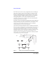
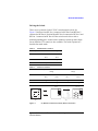
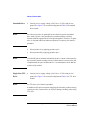
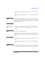
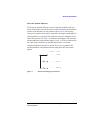
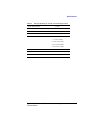
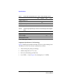
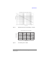
Operating and Service Manual
Agilent L7222C
Coaxial Transfer Switch
Manufacturing Part Number: L7222-90001
Printed in Malaysia
Print Date: March 2007
© Copyright Agilent Technologies, Inc 2007
Notices
Notices
© Agilent Technologies, Inc. 2007
No part of this manual may be reproduced in
any form or by any means (including electronic storage and retrieval or translation
into a foreign language) without prior agreement and written consent from Agilent
Technologies, Inc. as governed by United
States and international copyright laws.
Manual Part Number
L7222-90001
Edition
First edition, Mar 2007
Printed in Malaysia
Agilent Technologies, Inc.
Phase 3 Bayan Lepas Free Industrial Zone
Bayan Lepas, Penang 11900 Malaysia
Certification
Agilent Technologies certifies that this product met its published specifications at the
time of shipment from the factory. Agilent
Technologies further certifies that its calibration measurements are traceable to the
United States National Institute of Standards and Technology (NIST, formerly NBS),
to the extend allowed by the Institute’s calibration facility, and to the calibration facilities of the other International Standards
Organization members.
Warranty
The material contained in this document is
provided “as is,” and is subject to being
changed, without notice, in future editions.
Further, to the maximum extent permitted
by applicable law, Agilent disclaims all warranties, either express or implied, with
regard to this manual and any information
contained herein, including but not limited
to the implied warranties of merchantability
and fitness for a particular purpose. Agilent
shall not be liable for errors or for incidental
or consequential damages in connection
with the furnishing, use, or performance of
ii
this document or of any information contained herein. Should Agilent and the user
have a separate written agreement with
warranty terms covering the material in this
document that conflict with these terms,
the warranty terms in the separate agreement shall control.
Limitation of Warranty The foregoing warranty shall not apply to defects resulting
from the improper or inadequate maintenance by the Buyer, Buyer-supplied software or interfacing, unauthorized
modification or misuse, operation outside of
the environmental specifications for the
product, or improper site preparation or
maintenance.
NO OTHER WARRANTY IS EXPRESSED OR
IMPLIED. AGILENT SPECIFICALLY DISCLAIMS THE IMPLIED WARRANTIES OR
MERCHANTABILITY AND FITNESS FOR A
PARTICULAR PURPOSE.
Exclusive Remedies THE REMEDIES PROVIDED HEREIN ARE THE BUYER’S SOLE
AND EXCLUSIVE REMEDIES. AGILENT
SHALL NOT BE LIABLE FOR ANY DIRECT,
INDIRECT, SPECIAL, INCIDENTAL, OR CONSEQUENTIAL DAMAGES, WHETHER
BASED ON CONTRACT, TORT, OR ANY
OTHER LEGAL THEORY.
Technologies’ standard commercial license
terms, and non-DOD Departments and
Agencies of the U.S. Government will
receive no greater than Restricted Rights as
defined in FAR 52.227-19(c)(1-2) (June
1987). U.S. Government users will receive
no greater than Limited Rights as defined in
FAR 52.227-14 (June 1987) or DFAR
252.227-7015 (b)(2) (November 1995), as
applicable in any technical data.
Safety Notices
CAUTION
A CAUTION notice denotes a hazard. It calls
attention to an operating procedure, practice, or the like that, if not correctly performed or adhered to, could result in
damage to the product or loss of important
data. Do not proceed beyond a CAUTION
notice until the indicated conditions are
fully understood and met.
WARNING
Technology Licenses
The hardware and/or software described in
this document are furnished under a license
and may be used or copied only in accordance with the terms of such license.
Restricted Rights Legend
If software is for use in the performance of a
U.S. Government prime contract or subcontract, Software is delivered and licensed as
“Commercial computer software” as
defined in DFAR 252.227-7014 (June 1995),
or as a “commercial item” as defined in FAR
2.101(a) or as “Restricted computer software” as defined in FAR 52.227-19 (June
1987) or any equivalent agency regulation
orcontract clause. Use, duplication or disclosure of Software is subject to Agilent
A WARNING notice denotes a hazard. It
calls attention to an operating procedure,
practice, or the like that, if not correctly performed or adhered to, could result in personal injury or death. Do not proceed
beyond a WARNING notice until the indicated conditions are fully understood and
met.
Agilent L7222 Coaxial Transfer Switch Operating and
Service Manual
WEEE Compliance
WEEE Compliance
This product complies with the WEEE Directive (2002/96/EC) marking
requirements. The affixed label indicates that you must not discard this
electrical/electronic product in domestic household waste.
Product Category: With reference to the equipment types in the WEEE Directive
Annex I, this product is classed as a "Monitoring and Control Instrumentation"
product.
Do not dispose in domestic household waste.
To return unwanted products, contact your local Agilent office, or see
www.agilent.com for more information.
Printing Copies of Documentation from the Web
To print copies of documentation from the Web, download the PDF file from the Agilent web site:
•
Go to http://www.agilent.com.
•
Enter the document’s part number (located on the title page) in the Quick Search box.
•
Click GO.
•
Click on the hyperlink for the document.
•
Click the printer icon located in the tool bar.
Agilent L7222 Coaxial Transfer Switch Operating and
Service Manual
iii
Contacting Agilent (Americas, Asia Pacific & Japan)
Contacting Agilent (Americas, Asia Pacific & Japan)
Online assistance: www.agilent.com/find/assist
Americas
Brazil
(tel) (+55) 11 3351 7012
(fax) (+55) 11 3351 7024
Canada
(tel) +1 877 894 4414
(alt) +1 303 662 3369
(fax) +1 800 746 4866
Mexico
(tel) 1 800 254 2440
(fax) 1 800 254 4222
United States
(tel) 800 829 4444
(alt) (+1) 303 662 3998
(fax) 800 829 4433
Australia
(tel) 1 800 802 540
(fax) 1 800 681 776
(fax) 1 800 225 539
China
(tel) 800 810 0508
(fax) 800 810 0507
Hong Kong
(tel) 800 933 229
(fax) 800 900 701
India
(tel) 1600 112 626
(fax) 1600 113 040
Japan (Bench)
(tel) 0120 421 345
(alt) (+81) 426 56 7832
(fax) 0120 01 2144
Japan (On-Site)
(tel) 0120 421 345
(alt) (+81) 426 56 7832
(fax) 0120 012 114
Singapore
(tel) 1 800 275 0880
(fax) (+65) 6755 1214
South Korea
(tel) 080 778 0011
(fax) 080 778 0013
Taiwan
(tel) 0800 047 669
(fax) 0800 047 667
(fax) 886 3492 0779
Thailand
(tel) 1 800 2758 5822
(fax) 1 800 656 336
Malaysia
(tel) 1800 880 399
(fax) 1800 801 054
Asia Pacific and Japan
(tel) = primary telephone number; (alt) = alternate telephone number; (fax) = FAX number; * = in country
number 5/6/05
iv
Agilent L7222 Coaxial Transfer Switch Operating and
Service Manual
Contacting Agilent (Europe)
Contacting Agilent (Europe)
Online assistance: www.agilent.com/find/assist
Europe
Austria
(tel) 0820 87 44 11*
(fax) 0820 87 44 22
Belgium
(tel) (+32) (0)2 404 9340
(fax) (+32) (0)2 404 9395
Denmark
(tel) (+45) 7013 1515
(fax) (+45) 7013 1555
Finland
(tel) (+358) 10 855 2100
(fax) (+358) (0) 10 855
2923
France
(tel) 0825 010 700*
(fax) 0825 010 701*
Germany
(tel) 01805 24 6333*
(fax) 01805 24 6336*
Ireland
(tel) (+353) (0)1 890 924 204
(fax)(+353) (0)1 890 924
024
Israel
(tel) (+972) 3 9288 504
(alt) (+972) 3 9288 544
(fax) (+972) 3 9288 520
Italy
(tel) (+39) (0)2 9260 8484
(fax) (+39) (0)2 9544 1175
Luxemburg
(tel) (+32) (0)2 404 9340
(fax) (+32) (0)2 404 9395
Netherlands
(tel) (+31) (0)20 547 2111
(fax) (+31) (0)20 547 2190
Russia
(tel) (+7) 095 797 3963
(alt) (+7) 095 797 3900
(fax) (+7) 095 797 3902
Spain
(tel) (+34) 91 631 3300
(fax) (+34) 91 631 3301
Sweden
(tel) 0200 88 22 55*
(alt) (+46) (0)8 5064 8686
(fax) 020 120 2266*
Switzerland (French)
(tel) 0800 80 5353 opt. 2*
(fax) (+41) (0)22 567 5313
Switzerland (German)
(tel) 0800 80 5353 opt. 1*
(fax) (+41) (0)1 272 7373
Switzerland (Italian)
(tel) 0800 80 5353 opt. 3*
(fax) (+41) (0)22 567 5314
United Kingdom
(tel) (+44) (0)7004 666666
(fax) (+44) (0)7004 444555
(tel) = primary telephone number; (alt) = alternate telephone number; (fax) = FAX number; * = in country
number 5/6/05
Agilent L7222 Coaxial Transfer Switch Operating and
Service Manual
v
Contents
Contents
Notices . . . . . . . . . . . . . . . . . . . . . . . . . . . . . . . . . . . . . . . . . . . . . . . . . . . . . ii
WEEE Compliance . . . . . . . . . . . . . . . . . . . . . . . . . . . . . . . . . . . . . . . . . . . iii
Printing Copies of Documentation from the Web . . . . . . . . . . . . . . . . . . . . iii
Contacting Agilent (Americas, Asia Pacific & Japan). . . . . . . . . . . . . . . . . iv
Contacting Agilent (Europe) . . . . . . . . . . . . . . . . . . . . . . . . . . . . . . . . . . . . v
General Information . . . . . . . . . . . . . . . . . . . . . . . . . . . . . . . . . . . . . . . . . . . 1
L-Series Coaxial Transfer Switch Overview . . . . . . . . . . . . . . . . . . . . . 1
Features . . . . . . . . . . . . . . . . . . . . . . . . . . . . . . . . . . . . . . . . . . . . . . . . . 1
Driving the Switch. . . . . . . . . . . . . . . . . . . . . . . . . . . . . . . . . . . . . . . . . 3
Standard Drive . . . . . . . . . . . . . . . . . . . . . . . . . . . . . . . . . . . . . . . . . . . . 4
Single Line TTL Drive . . . . . . . . . . . . . . . . . . . . . . . . . . . . . . . . . . . . . 4
Dual Line TTL Drive. . . . . . . . . . . . . . . . . . . . . . . . . . . . . . . . . . . . . . . 5
Electronic Position Indicator . . . . . . . . . . . . . . . . . . . . . . . . . . . . . . . . . 6
Specifications . . . . . . . . . . . . . . . . . . . . . . . . . . . . . . . . . . . . . . . . . . . . . . . . 7
Environmental Specifications . . . . . . . . . . . . . . . . . . . . . . . . . . . . . . . . . . 11
Physical Specifications. . . . . . . . . . . . . . . . . . . . . . . . . . . . . . . . . . . . . . . . 12
Installation . . . . . . . . . . . . . . . . . . . . . . . . . . . . . . . . . . . . . . . . . . . . . . . . . 13
Initial Inspection . . . . . . . . . . . . . . . . . . . . . . . . . . . . . . . . . . . . . . . . . 13
Operating Instruction . . . . . . . . . . . . . . . . . . . . . . . . . . . . . . . . . . . . . . . . . 14
Operator’s Check . . . . . . . . . . . . . . . . . . . . . . . . . . . . . . . . . . . . . . . . . 14
Performance Tests . . . . . . . . . . . . . . . . . . . . . . . . . . . . . . . . . . . . . . . . . . . 16
Service Instructions . . . . . . . . . . . . . . . . . . . . . . . . . . . . . . . . . . . . . . . . . . 16
Adjustment. . . . . . . . . . . . . . . . . . . . . . . . . . . . . . . . . . . . . . . . . . . . . . 16
Repair. . . . . . . . . . . . . . . . . . . . . . . . . . . . . . . . . . . . . . . . . . . . . . . . . . 16
Maintenance. . . . . . . . . . . . . . . . . . . . . . . . . . . . . . . . . . . . . . . . . . . . . 16
vi
Agilent L7222 Coaxial Transfer Switch Operating and
Service Manual
General Information
General Information
L-Series Coaxial Agilent L7222C coaxial transfer switch is designed for flexibility in signal
Transfer Switch routing applications and provides exceptional insertion loss repeatability of
0.03 dB, low insertion loss and high isolation > 80 dB.
Overview
Figure 1
L7222C Coaxial Transfer Switch
Table 1 shows general details of L7222C coaxial transfer switch.
Table 1
Features
•
•
•
•
•
General Information on L7222C Coaxial Transfer Switch
Model
Frequency Range
Configuration
L7222C
DC to 26.5 GHz
DPDT
Guaranteed 0.03 dB insertion loss repeatability for 2 million cycles
Excellent isolation, typically > 80 dB at 26.5 GHz
Opto-electronic indicators and interrupts
Magnetic latching
TTL/5V CMOS compatible (optional)
Agilent L7222C Coaxial Transfer Switch Operating and
Service Manual
1
General Information
The L7222C can be used in a variety of applications such as switching two
inputs and two outputs, signal reversal switching or as a drop-out switch.
Innovative design and careful process control mean the L7222C meet the
requirements for highly repeatable switching elements in test instruments
and switching interfaces. L7222C offers exceptional insertion loss
repeatability, reducing sources of random errors in the measurement path
and improving measurement uncertainty.
Switch life is a critical consideration in production test systems, satellite and
antenna monitoring systems and test instrumentation. The longevity of this
switch increases system uptime and lowers the cost of ownership by
reducing calibration cycles and switch maintenance.
Opto-electronic interrupts and indicators improve reliability and extend the
life of the switch by eliminating DC circuit contact failures characteristic of
conventional electromechanical switches. The L7222C have circuits that
interrupt the current to all the solenoids once switching is complete and offer
independent indicators that are controlled by optical interrupts. These
indicators provide a closed path between the indicator common pin and the
corresponding sense pin of the selected path.
+24 VDC (1)
Gnd. (9)
Drive A (3)
Drive B (5)
TTL Drive A (7)
TTL Drive B (8)
Control
Input
Position A
1-2
3-4
Control
circuit
Position B
2-3
1-4
(4)
A
Figure 2
2
1
2
4
3
(2)
Com
(6)
B
Indicators
Agilent L7222C Coaxial Transfer Switch Schematic
Agilent L7222C Coaxial Transfer Switch Operating and
Service Manual
General Information
Driving the Switch
There are two positions for the L7222C coaxial transfer switch. See
Figure 3. Position A has RF Port 1 connected to RF Port 2 and RF Port 3
connected to RF Port 4. Position B has RF Port 2 connected to RF Port 3 and
RF Port 1 connected to RF Port 4. Either switch can be driven with a
standard grounding drive control with or without a separate ground. Single
line or Dual line TTL control are also available. The switch operates in a
break-before-make mode.
Table 2
Standard Drive Control
RF path
Standard drive voltage
Drive A
Drive B
Pin 3
Pin 5
Position A
Ground
Open
Position B
Open
Ground
Table 3
TTL Drive Control
RF path
Single line TTL/5V CMOS drive
voltage
Dual line TTL/5V CMOS drive
voltage
TTL Drive A
TTL Drive B
TTL Drive A
TTL Drive B
Pin 7
Pin 8
Pin 7
Pin 8
Position A
High
High
High
Low
Position B
Low
High
Low
High
Option 100
Standard
Position A
1 to 2
3 to 4
Position B
2 to 3
1 to 4
(a)
Figure 3
1
2
3
4
5
6
7
8
9
10
Ribbon Cable
Function
+24 VDC
Ind. Comm.
Drive “A”
Ind. “A”
PIN #
1
2
3
4
5
6
7
8
9
10
Drive “B’
Ind. “B”
TTL
TTL Compl.
Comm. Gnd.
Not Used
Solder Terminals
2
3
4
5
2
7
1
1
6
7
8
9
10
4
8
3
Ribbon Cable
6
5
9
NOTE:
RF Port 1 is located directly behind
the 10-pin ribbon cable connector.
(b)
(a) RF Port Connections and (b) Drive Connections
Agilent L7222C Coaxial Transfer Switch Operating and
Service Manual
3
General Information
Standard Drive
•
NOTE
Pin 9 does not need to be grounded for the switch to operate in standard
drive mode. If pin 9 is not grounded, the position indicators will only
function while the appropriate drive has ground applied. Therefore, if a pulse
drive is used and continuous indicator operation is required, pin 9 must be
grounded.
•
•
Connect pin 1 to supply voltage (+20 Vdc to +32 Vdc) and pin 9 to
ground. See Figure 3 for connection diagram and Table 2 for standard
drive control.
Select position A by applying ground to pin 3.
Select position B by applying ground to pin 5.
NOTE
After the RF path is switched and latched, the drive current is interrupted by
the electronic position-sensing circuitry. Pulsed control is not necessary, but
if implemented, the pulse width must be 15 ms minimum to ensure that the
switch is fully latched.
Single Line TTL
Drive
•
NOTE
For TTL drive, pin 9 must be grounded.
Connect pin 1 to supply voltage (+20 Vdc to +32 Vdc) and pin 9 to
ground. See Figure 3 for connection diagram and Table 3 for TTL drive
control.
In addition to the quiescent current supplying the electronic position-sensing
circuitry, the drive current flows out of pin 9 (during switching) when using
TTL drive.
4
Agilent L7222C Coaxial Transfer Switch Operating and
Service Manual
General Information
•
Select position A by applying TTL “High” to pin 7 and TTL “High” to
pin 8.
•
Select position B by applying TTL “Low” to pin 7 and TTL “High” to
pin 8.
NOTE
After the RF path is switched and latched, the drive current is interrupted by
the electronic position-sensing circuitry. Pulsed control is not necessary, but
if implemented, the pulse witdth must be 15 ms minimum to ensure that the
switch is fully latched.
Dual Line TTL
Drive
•
NOTE
For TTL drive, pin 9 must be grounded
Connect pin 1 to supply voltage (+20 Vdc to +32 Vdc) and pin 9 to
ground. See Figure 3 for connection diagram and Table 3 for TTL drive
control.
In addition to the quiescent current supplying the electronic position-sensing
circuitry, the drive current flows out of pin 9 (during switching) when using
TTL drive.
NOTE
•
Select position A by applying TTL “High” to pin 7 and TTL “Low” to
pin 8.
•
Select position B by applying TTL “Low” to pin 7 and TTL “High” to
pin 8.
After the RF path is switched and latched, the drive current is interrupted by
the electronic position-sensing circuitry. Pulsed control is not necessary, but
Agilent L7222C Coaxial Transfer Switch Operating and
Service Manual
5
General Information
if implemented, the pulse width must be 15 ms minimum to ensure that the
switch is fully latched.
6
Agilent L7222C Coaxial Transfer Switch Operating and
Service Manual
General Information
Electronic Position Indicators
The electronic position indicators consist of optically isolated, solid state
relays which are driven by photo-electric sensors coupled to the mechanical
position of the RF path’s moving elements (See Figure 4). The circuitry
consists of a common which can be connected to an output corresponding to
either postition A or position B. The solid state relays are configured for AC
and/or DC operation. See Table 5 for indicator specifications. The electronic
position indicators require that the supply (+20 to +32 VDC) be connected to
pin 1 but requires that pin 9 be grounded if pulse drive is used and
continuous indicators operation is desired. If pin 9 is not grounded, the
position indicators will function while the appropriate drive has ground
applied.
Figure 4
Pin number
Function
2
Common
4
Position “A”
6
Position “B’
Pin Function Diagram for Indicator
Agilent L7222C Coaxial Transfer Switch Operating and
Service Manual
7
Specifications
Specifications
Specifications refer to the performance standards or limits against which the
L7222C coaxial transfer switch is tested.
Typical characteristics are included for additional information only and they
are not specifications. These are denoted as "typical", "nominal" or
“approximate" and are printed in italics.
Table 4
General Specifications for L7222C Coaxial Transfer Switch
Agilent Model Number
L7222C
Maximum power rating
Switching1
1W CW
Non-switching
50W Pk (not to exceed 1 W average)
Life
2 million cycles minimum
Switching Speed
15 ms
1. Hot switching. For cold switching, see supplement specifications on page 9.
Table 5
Indicator Specifications for L7222C Coaxial Transfer Switch
Agilent Model Number
L7222C
Maximum withstand voltage
60 V
Maximum current capacity
100 mA
Maximum “ON” resistance
50 Ω
Maximum “OFF” resistance
1GΩ
8
Agilent L7222C Coaxial Transfer Switch Operating and
Service Manual
Specifications
Table 6
RF Specifications for L7222C Coaxial Transfer Switch
Agilent Model Number
Frequency Range
Insertion Loss
Isolation
SWR
L7222C
DC to 26.5 GHz
0.2 dB + 0.025 x Freq (GHz)
110 dB - 2.0 x Freq (GHz)
< 1.1 (DC to 2 GHz)
< 1.15 (2 to 4 GHz)
< 1.25 (4 to 12.4 GHz)
< 1.40 (12.4 to 20 GHz)
< 1.65 (20 to 26.5 GHz)
Repeatability
Characteristics
Connectors
< 0.03 dB typical
50 Ω
SMA (f)
Agilent L7222C Coaxial Transfer Switch Operating and
Service Manual
9
Specifications
Table 7
Switch Drive Specifications for L7222C Coaxial Transfer Switch
Min
Nominal
Max
Unit
20
24
32
V
Supply Voltage, Vcc
Supply Current, Icc
mA
2001
25
Supply Current (quiescent)
50
mA
1. Switching: Pulse width > 15 ms: Vcc = 24 VDC
Table 8
TTL Drive Specifications for L7222C Coaxial Transfer Switch (Option
T24)
Min
Nominal
3
High level input
Low level input
Max high input current1
1
Max
Unit
7
V
0.8
V
1.4
mA
1. Vcc = Max, Vinput = 3.85 Vdc
Supplement Specifications (Cold Switching)
Figure 5 illustrates the maximum incident CW power (cold switching) from
100 MHz to 18 GHz. The reference conditions are as below:
•
•
•
•
10
Cold switching only (NO hot switching)
Ambient temperature of 75oC or less
Sea level (0.88 derating @15,000 feet)
Low VSWR < 1.2 (See Figure 6 for derating above 1.2 VSWR)
Agilent L7222C Coaxial Transfer Switch Operating and
Service Manual
Specifications
Figure 5
Maximum Incident Power (Cold Switching) vs. Frequency
Power derating factor versus VSWR
Power derating factor
1
0.9
0.8
0.7
0.6
0.5
1
1.5
2
2.5
3
VSWR (:1)
Figure 6
Power Derating Factor vs VSWR
Agilent L7222C Coaxial Transfer Switch Operating and
Service Manual
11
Environmental Specifications
Environmental Specifications
The L-series multiport coaxial switches are designed to fully comply with
Agilent Technologies’ product operating environmental specifications as
shown in Table 9.
Table 9
L7222C Coaxial Transfer Switch Environmental Specifications
Temperature:
Operating
-25oC to +75oC
Storage
-55oC to +85oC
Cycling
-55oC to +85oC, 10 cycles per MIL-STD-202F, Method 107D,
Condition A (modified)
Humidity:
Operating
95% RH at 65oC, 10 days per MIL-STD-202F, Method 106E
Shock:
Half-sine
500 G @ 0.5 ms, 3 drops/direction, 18 total
Operating
50 G @ 6 ms, 18 total
Vibration:
Operating
7 G rms, 5 to 2000 Hz at 0.25 in p-p
Survival
20 G rms, 20 to 2000 Hz at 0.06 in p-p, 4 min/cycle, 4 cycles/axis
Random
2.41 G rms, 10 minutes/axis
Altitude:
Storage
<15,240 meters (50,000 feet) per MIL-STD-202F, Method 105C,
Condition B
ESD Immunity:
Direct discharge 4 kV (to outer conductor) per IEC 61000-4-2
Air discharge
8 kV (to center conductor) per IEC 61000-4-2
RFI:
Radiated Emission per CISPR 11
12
Agilent L7222C Coaxial Transfer Switch Operating and
Service Manual
Physical Specifications
Physical Specifications
The physical specifications of L7222C coaxial transfer switch is illustrated
in Table 10.
Table 10
L7222C Coaxial Transfer Switch Physical Specifications
Dimensions
Per Figure 7
Net weight, kg (lb)
0.1 (0.23)
Standard
55.20
(2.173)
B
4.85
(.191)
3.36 TYP
(.143)
5.66TYP
(.223)
2.54TYP
(.100)
2.54TYP
(.100)
A
31.75 TYP
(1.250)
C
4X M2.5 X 0.45
23.11 TYP
(.910)
6.5
Option 100
12.89
TYP
(.507)
55.20
(2.173)
8.32TYP
(.328)
2.54 TYP
(.100)
4.85
(.191)
7.94
(.313)
6.00 TYP
(.236)
A
5.93 TYP
(.233)
D
4.94TYP
(.194)
4.94TYP
(.194)
6.00TYP
(.236)
3.63TYP
(.143)
5.66TYP
(.223)
2.54TYP
(.100)
6.00TYP
(.236)
Option 100 and 201
3X 3.86
(.152)
1.60
(.063)
20.32
(.800)
9.65 TYP
(.380)
E
1
4.85
(.191)
55.37
45.72 (2.180)
(1.800)
31.75
(1.250)
5.93 TYP
(.233)
33.50
(1.319)
19.81
(.780)
10.16
(.400)
56.80
(2.236)
D
Note: Dimensions are in millimeters and (inches) nominal unless specified.
L7222C
(millimeter
(inches)
Figure 7
A
B
SMA (f)
8.32 (0.328)
TYP
C
D
68.37 (2.692) 69.46 (2.735)
REF
REF
E
6.72 (0.265)
REF
Dimensions of L7222C Coaxial Transfer Switch
Agilent L7222C Coaxial Transfer Switch Operating and
Service Manual
13
Installation
Installation
Initial Inspection 1. Inspect the shipping container for damage. If the shipping container or
cushioning material is damaged, it should be kept until the contents of
the shipment have been checked for completeness and the instrument
has been checked both mechanically and electrically.
•
•
Check for mechanical damage such as scratches or dents.
Procedures for checking electrical performance are given under
“Operator’s Check” or “Performance Tests’.
2. If the contents are incomplete, if there is mechanical damage or defect,
or if the instrument does not pass the electrical performance test, contact
the nearest Agilent Technologies Sales and Service office. Refer to the
Service and Support information in the front matter of this manual.
Agilent Technologies will arrange for repair or replacement of the
damaged or defective equipment. Keep the shipping materials for the
carrier’s inspection.
3. If you are returning the instrument under warranty or for service,
repackaging the instrument requires original shipping containers and
materials or their equivalents. Agilent Technologies can provide
packaging materials identical to the original materials. Refer to Service
and Support information in the front matter of this manual for the
Agilent Technologies nearest you. Attach a tag indicating the type of
service required, return address, model number, and serial number. Mark
the container FRAGILE to insure careful handling. In any
correspondence, refer to the instrument by model number and serial
number.
14
Agilent L7222C Coaxial Transfer Switch Operating and
Service Manual
Operating Instruction
Operating Instruction
Operator’s
Check
The operator’s check is supplied to allow the operator to make a quick check
of the coaxial transfer switch prior to use or if a failure is suspected.
CAUTION
ESD exceeding the level specified in Table 9 or RF power applied is greater
than the maximum specified as in Table 4 may cause permanent damage to
the device.
Description
The coaxial transfer switch is connected to a network analyzer configured
for the s-parameter measurement. The network analyzer may be set to sweep
over the whole or selected frequency range of the switch to be verified. The
s-parameters measurement is the best way to determine if the switch is
working properly.
Figure 8
Connection to Perform Quick Check
Agilent L7222C Coaxial Transfer Switch Operating and
Service Manual
15
Operating Instruction
Quick-Check Procedure
1. Connect Port 1 and Port 2 of the network analyzer to switch’s Port 1 and
Port 2 respectively.
2. Refering to Table 2 (standard drive) or Table 3 (TTL drive), apply
appropriate drive voltage to ensure switch is in position A (path 1
connected to path 2, path 3 connected to path 4). Measure S11, S21 and
S22 and verify against specifications in Table 6.
3. Now, still in position A, disconnect switch’s Port 1 and Port 2 from
network analyzer. Then, connect network analyzer’s Port 1 and Port 2 to
Port 3 and Port 4 of the switch. Measure S11, S21 and S22 and verify
against specifications in Table 6.
4. Disconnect Port 3 and Port 4 from network analyzer. Connect Port 1 and
Port 2 of the network analyzer to switch’s Port 1 and Port 4 respectively.
5. Refering to Table 2 (standard drive) or Table 3 (TTL drive), apply
appropriate drive voltage to ensure switch is in position B (path 1
connected to path 4, path 2 connected to path 3). Measure S11, S21 and
S22 and verify against specifications in Table 6.
6. Now, still in position B, disconnect switch’s Port 1 and Port 2 from
network analyzer. Then, connect network analyzer’s Port 1 and Port 2 to
Port 2 and Port 3 of the switch. Measure S11, S21 and S22 and verify
against specifications in Table 6.
.
16
Agilent L7222C Coaxial Transfer Switch Operating and
Service Manual
Performance Tests
Performance Tests
The coaxial transfer switch can be tested to the accuracy of the specifications
with a network analyzer or equivalent equipment of suitable accuracy. If a
network analyzer is available, test the instrument using the procedure in the
analyzer’s operating manual.
Service Instructions
Adjustment
The coaxial transfer switch do not have internal adjustments and should not
be opened.
Repair
The L7222C coaxial transfer switch is not recommended for repair as most
components are not easily removed.
Maintenance
The connectors, particularly the connector faces, must be kept clean. For
instruction on connecting and care of your connectors, refer to the
Microwave Connector Care Quick Reference Card (08510-90360).
Agilent L7222C Coaxial Transfer Switch Operating and
Service Manual
17
Service Instructions
18
Agilent L7222C Coaxial Transfer Switch Operating and
Service Manual