1
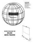
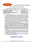
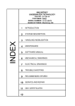
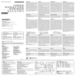
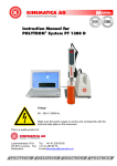
315, 712A and 912
Operating Instructions
Please read and save these instructions. Read carefully before attempting to assemble, install, operate or maintain the product described. Protect yourself
and others by observing all safety information. Failure to comply with instructions could result in personal injury and/or property damage! Retain instructions
for future reference.
®
Boat Trailer Winch
Model 315
Description
Trailer winches are used for launching and
loading boats. This winch features powerin/free-wheel out capabilities. A lanyard
cord is supplied for remote operation.
Unpacking
When unpacking, inspect carefully for any
damage that may have occurred during
transit. Make sure any loose fittings, bolts,
etc., are tightened before putting unit into
service.
Models 712A
912
General Safety Information
Danger means a
hazard that will
cause death or serious injury if the warning
is ignored.
Warning means a
hazard that could
cause death or serious injury if the warning
is ignored.
Caution means a
hazard that may
cause minor or moderate injury if the
warning is ignored. It also may mean a
hazard that will only cause damage to
property.
NOTE: Note means any additional
information pertaining to the product or its
proper usage.
The following safety precautions must be
followed at all times:
1. Read all manuals included with this
product carefully. Be thoroughly
familiar with the controls and the
proper use of the equipment. Only
persons well acquainted with these
rules of safe operation should be
allowed to use the winch.
Always unplug the
wiring harness
to prevent accidental starting before
attempting to install, service, relocate or
perform any maintenance.
people or animals.
3. Stand away from the winch when in
use and keep children away from
winch area at all times.
Always stand clear
of the area behind
and between the load or anchor point and
the winch. Serious injury could occur, if
the cable breaks.
4. Always keep hands clear of cable
spool (drum area).
5. Do not wear loose fitting clothing,
scarves, or neck ties. Loose clothing
may become caught in moving parts
and result in serious personal injury.
6. Never use the winch for overhead
lifting.
7. Always wire the winch with circuit
breakers. Failure to use the breakers
could cause overheating thus creating
a potential fire hazard or motor
damage.
2. Never use the winch to lift or move
The cable fasteners
on this or any winch
are not designed to hold rated loads.
Always leave a minimum of five wraps of
cable on the drum at the bottom layer to
achieve a rated load.
8. Inspect the entire cable for weak or
worn condition or kinking (short tight
twist or curl) before each use.
9. When replacing the cable, always use
a Powerwinch cable with the same
winch rating and cable strength.
10. Never substitute rope for cable.
Possible injury could occur.
11. Do not attempt to pull a load greater
than the rated load of the winch.
12. Do not use the winch to hold or
support the load once a job is
complete or to permanently secure
the load. Damage could occur to the
winch or the load.
13. Never wrap the winch cable around
the load. Use an Ecostrap™ or chain
to prevent the cable from kinking or
fraying.
P7033603AV 12/06
© 2006 Carefree of Colorado
1
Operating Instructions
14. Always wear leather gloves when
handling the cable. Steel cable can
cause hand injuries.
when pulling a load with the winch.
After using the
winch, always
disconnect the power cord from the
socket to avoid moisture collection in the
socket and prevent the possibility of short
circuiting.
a specific application depends on the
weight of the load, condition of the trailer
rollers, and the degree of the loading
ramp incline. The chart below is based
on a single line pull and is a guideline to
aid in calculating pulling requirements.
16. Do not operate the winch under the
influence of drugs, alcohol, or other
medication.
Secure the boat to
the trailer after
winching the boat onto the trailer or
personal injury could occur.
Specifications
15. Always block the vehicle wheels to
help prevent the vehicle from rolling
Various load conditions will affect winch
performance. The line pull required for
NOTE: The noise level of this winch in operation is below 98db (A).
Chart 1 - Approximate Rolling load capacities
% incline
(° incline)
Level
Surface
0°
5%
3°
10%
6°
20%
11°
30%
17°
50%
26°
70%
35°
100%
45°
315
712A
912
16,500
24,000
40,000
10,005
13,340
23,345
7,530
10,040
17,570
5,250
6,800
11,900
3,915
5,220
9,135
2,790
3,720
6,510
2,295
3,060
5,355
1,935
2,580
4,515
• A 10% incline (or 6°) is 1 foot rise in 10 ft.
• To convert from pounds (lbs) to kilos (kgs) divide by 2.2.
• Capacity can be increased (almost doubled) by using a pulley block.
Chart 2 - Winch and boat capacities
Model
Single Line
Capacity
Double
Line Pull
315
712A
912
1,650 lb.
2,400 lb.
4,000 lb.
—
4,300 lb.
7,500 lb.
Approximate*
Boat Weight
Approximate *
Boat Size
4,000 lb.
7,500 lb.
11,500 lb.
14-17 ft.
17-23 ft.
23-30 ft.
* Boat size and weight is approximate and varies depending on boat type. When calculating boat weight be sure to use fully loaded
weight - including boat, motor, fuel, water, gear etc.
Chart 3 - Winch specifications
Model
Line Speed
@ Capacity
(FPM)
Gear
Ratio
Voltage
(Volts)
Circuit
Breaker
(Amps)
Unit
Weight
(lbs)
Depth
Height
Width
315
712A
912
15
14
8
270:1
225:1
450:1
12
12
12
30
60
60
22
34
39
10”
10”
10”
10”
10”
10”
8”
8”
8”
2
Operating Instructions
eye bolt on the winch stand as close as
possible to the base of the winch. If a
Quick Mount Kit is used, make sure the
winch is in the forward position before
installing the eye bolt.
Installation
MOUNTING
The winch can be mounted on the
trailer in the same position and location
as an existing hand winch. After
removing the hand winch, bolt the
Powerwinch unit using a minimum of
(2) 3/8” Grade 5 machine bolts and lock
nuts. The Powerwinch Quick Mount Kit
(P7700000AJ) is available from the dealer.
PERMANENT WIRING FOR MODELS
712A AND 912
To permanently wire the winch, refer to
Figure 1 follow the outlined procedures.
1. Attach the circuit breaker to the
positive (+) battery post or to the
positive (+) battery side of the starter
solenoid (See Figure 1).
The cable hook on the winch and the bow
eye on the boat should be at the same
height when the boat is in the fully loaded
position on the trailer. If the bow eye is
too high, extra pull is required of the winch
and extra stress is exerted on the boat’s
stern and bow eye.
Never attach the
circuit breaker to the
battery ground terminal.
2. Run the wire under the vehicle to the
battery, attaching at suitable intervals
to the vehicle frame. Use nylon wire
ties (not supplied) to secure the wire
to the vehicle frame about every 18
inches. If no wire ties are available
use electrician’s tape. Avoid sharp
edges or places where the wire might
rub.
To achieve equal height of the winch and
boat, raise or lower the winch stand. In
most cases, the trailer manufacturer will
have an adapter available for use with a
winch.
A minimum of 12
inch clearance is
required between the winch and the bow
eye to prevent the cable hook from being
drawn into the winch drum when the boat
is in the fully loaded position on the trailer.
3. Attach the ground wire (black) to the
vehicle frame using a 5/16” bolt and
lock nut. Before attaching the wire,
clean the metal with a wire brush,
steel wool, or sandpaper.
If necessary, extend the bow stop to
obtain the clearance.
When using a double line pull (using
a pulley block), install an appropriate
Battery
Terminal
4. Remove the knock out plug in the
spare tire well and draw the excess
wire up into the vehicle.
PERMANENT WIRING FOR
MODEL 315
To permanently wire the winch, refer to
Figure 2 follow the outlined procedures.
1. Strip approximately 3/8” of insulation
from each wire end.
2. Grasp one end of the red and black
wires, insert the wires into rubber boot
and the plug cover.
3. Attach the red wire to the gold
terminal and attach the black wire to
the silver terminal.
4. Firmly tighten the two screws that hold
the wires in place. Screw the plug cover
into the plug base and slide the rubber
boot firmly over the plug.
5. Run the red and black wires under
or through the vehicle. Drill holes to
feed the wires and be sure to protect
the wires from damage by using
grommets (not supplied). Worn wire
insulation can cause short circuits. At
10” intervals, join the red and black
wires together using electrical tape or
wire ties.
6. Attach the 5/16” ring terminal to the
end of the black wire and crimp
together.
7. Attach the 3/16” ring terminal to the end
*
5/16" Bolt
12 Volt Car
Or Truck Battery
*
Vehicle
Frame
* NOT SUPPLIED
Figure 1 - Permanent Wiring Hookup for Models 712A and 912
3
5/16"Lock Washer
And Nut
*
Operating Instructions
of the red wire and crimp together.
Connect the
positive wire before
grounding the black wire to the vehicle
frame to prevent electrical arcing.
8. Connect the red wire with the 3/16”
ring terminal to the circuit breaker.
9. Connect the circuit breaker to the
battery terminal.
10. Attach the black wire with the 5/16”
ring terminal to the vehicle frame.
Never attach the
red wire with
the circuit breaker to the negative (-)
or ground battery terminal. Incorrect
wiring will short circuit and damage
the circuit breaker and/or motor which
could cause damage to the vehicle and
winch.
11. Insert the plug into the power socket
on the winch.
TEMPORARY WIRING
2. Run the red wire (with the circuit
breaker) to the battery and clip the
wire to the hot (positive) side of the
battery.
3. Clip the black wire to the vehicle frame
or negative side of the battery.
To temporary wire the winch, follow the
outlined procedures. A complete wiring
harness is available from the dealer (Part
Number P7866000AJ) for Models 712A
and 912. Order part number P7865900AJ
for Model 315.
1. Attach two large “alligator” type clips,
one to the circuit breaker and one to
the end of the black wire.
Red
Wire
Rubber
Boot
Red
Wire
Gold
Terminal
Circuit
Breaker
Black
Wire
Battery
Terminal*
3/16
Ring
Terminal
Silver
Terminal
Black
Wire
Bolt*
12 Volt Car
Or Truck Battery
* NOT SUPPLIED
5/16
Ring
Terminal
Vehicle
Frame
Lock Washer*
Nut *
Figure 2 - Permanent Wiring For Model 315
4
Power
Socket
Toggle
Switch
Operating Instructions
Operation
UNLOADING
To unload the boat, and follow the
outlined procedures.
Clear the area
around and behind
the boat of people, animals, and obstructing
objects before loading or unloading or
personal injury could occur.
1. Attach the winch cable hook to the
bow eye on the boat.
Always stand clear
of the area behind
and between the load or anchor point and
the winch. Serious injury could occur if the
cable breaks.
The clutch control knob on the side of the
winch controls the loading and unloading
operation (See Figure 3). Turning the
knob counterclockwise releases the
brake and allows the cable to free-wheel
out.
Winch
Cable
Hook
Turn
COUNTERCLOCKWISE
To Release
Brake
bow eye. Be sure to keep constant
pressure on the cable when rewinding
the cable with no load. A loose cable
may rewind improperly and damage
the levelwind plate. Secure the cable
hook to prevent personal injury or
property damage.
LOADING
1. Align the boat and trailer.
Always stand clear
of the area between
the load or anchor point and the winch.
Serious injury could occur if the cable
breaks.
3. Allow the boat to slide off the trailer (a
slight push may be necessary to start
the boat down the run).
The following warning is for
Model 315 ONLY.
Once the boat is
moving, do not
attempt to slow or stop the boat motion by
turning the clutch knob. The knob will freewheel with the outgoing cable. Any contact
with the clutch knob while in motion could
result in personal injury.
The following statement is for Models 712A
and 912 ONLY.
If needed, turn the clutch knob
counterclockwise to use the brake to slow
the boat at launch.
4. When the boat is in the water, release
the winch cable hook from the
2. Turn the clutch control knob clockwise
until tight. DO NOT overtighten the
knob or clutch damage will occur (See
Figure 5).
Emergency
Hand Crank
Outer
Nut
Inner Nut
3. Turn the clutch control knob
clockwise until finger tight to set
the brake (See Figure 4).
Inner
Nut
Outer
Nut
Emergency
Hand Crank
Turn
Clockwise
To Set
Brake
Clutch
Control Knob
Figure 5
Figure 4
2. Turn the clutch knob slowly in
a counterclockwise motion to
release the brake on the winch.
1. Unplug the winch from the wiring
harness.
2. Free-wheel the winch cable out and
attach the cable hook to the eye on
the boat.
Clutch
Control Knob
Figure 3
the winch in manual mode, follow the
procedures outlined below.
4. Step clear of the winch and winch
cable area and power in the cable
until the boat touches the bow stop.
5. Secure the boat to the trailer once the
boat is fully loaded.
Do not use the
winch to hold the
weight of the boat while in transit.
Always secure the boat to the
trailer before towing the boat and
trailer.
6. Remove the winch cable hook from
the bow eye and power-in the cable.
Secure the cable hook to prevent
personal injury or property damage.
EMERGENCY HAND CRANK
The emergency hand crank is included
on some models. This emergency hand
crank should only be used when there
is no power source i.e. dead battery. The
emergency hand crank should never
be used to help a running motor. To use
5
3. Remove the outer nut shown in Figure
5 and place the emergency hand
crank on the shaft.
4. Tighten the outer nut firmly against the
hand crank.
After using the emergency hand crank,
follow the procedures outlined below.
1. Remove the outer nut shown in Figure
5 and remove the emergency hand
crank off the shaft.
2. Tighten the outer nut firmly against the
inner nut.
Maintenance
LUBRICATION
The cable should be lubricated a
minimum of once a year with Whitmore’s
Wire Rope Spray, WD40 or a similar
product. Spray the shaft and the cable
as the cable is being wound. Remove the
cover and lubricate the gears a minimum
of once a year with a lithium base grease.
Be careful not to get grease on the clutch
lining.
Operating Instructions
Cable
Fastener
Counterbore
Cable Drum
2"
Insert
New Cable
Figure 6 - Cable Replacement
CABLE REPLACEMENT
Always unplug the
wiring harness
to prevent accidental starting before
attempting to install, service, relocate or
perform any maintenance.
To replace the cable, follow the outlined
procedures. Use an exact replacement
Powerwinch cable. The winch rating and
cable strength are carefully matched.
Never replace the cable with rope.
1. Unplug the wiring harness. Loosen
the clutch knob and
free-wheel the cable out.
2. Remove the two cover rods and the
four cover screws.
3. Cut the old cable approximately 2”
from the drum and push the remaining
cable and fastener through the drum to
remove (See Figure 6).
4. Insert the new cable into the drum
shaft hole at the end opposite
the counterbored end. Draw the
cable through the hole and out the
counterbored side of the shaft.
until the cable end is flush with the
end of the fastener.
6. Crimp the fastener onto the cable and
pull the cable through the drum shaft
until the fastener seats inside the
counterbore.
7. Install the cover, two cover rods and
the four cover screws and connect the
wiring harness.
8. Power-in the cable with a light load to
help wind the cable straight into the
drum.
LEVELWIND PLATE
1. When powering-in the cable, the
motor will continue to run for a few
seconds after releasing the switch,
especially without a load. Be sure
to allow for the extra cable when
powering-in. Do not let the cable
hook go into the winch and bend the
level wind plate.
5. Push the cable through the fastener
6
Troubleshooting Chart
Symptom
Winch will not operate
Possible Cause(s)
Corrective Action
a. Start checking the wiring at the battery. Bypass the circuit breakers
and test the winch. If the winch operates, replace the circuit
breakers.
1. Disconnected or bad wiring or
bad circuit breakers
b. Check the wiring insulation for worn or bare spots that may be
causing a short.
c. Check all connections for tightness.
a. Check the male connection at the end of the wiring kit by using
probe light across the two prongs inside the plug. If the light
illuminates, the wiring is correct.
2. Bad plug
b. Remove the two cover connecting screws and rods the cover
containing the female socket. Plug the male socket into the female
socket. Use a probe light across the two connections on the
underside of the female socket. Replace the ap pro priate socket if
the light does not illuminate. If the light illuminates, check the switch
and/or motor.
Clutch does not hold
1. Worn or broken roller clutch
Replace roller clutch (Models 712A and 912 only).
2. Worn gears or clutch lining
Replace gears or lining.
Technical Information
For information on the operation or repair, please call
AU: 1800-059-899 or NZ: 0800-876-526.
Replacement Parts Information
For information regarding where to order replacement parts, call the above numbers. Please have the following information available:
Winch Model Number
Winch Serial Number
Part Number and Description
Address correspondence to:
Trail Com AU Limited
Unit 5, 25-27 South Link
Dandenong, Melbourne
Victoria 3175
Trail Com Limited
15 Oak Road,
Manukau, Auckland
New Zealand
or
7
Operating Instructions
Limited Warranty
A. This Limited Warranty is given by the Powerwinch Division of the Scott Fetzer Company (the “Company”) to the original
purchaser (the “Purchaser”) of a Powerwinch Product (the “Product”) specified in this manual. This Limited Warranty is not
transferable to any other party.
B. Responsibilities of the Company under this Limited Warranty:
1. Repair or replace (at the discretion of the Company) any part or parts of the Product found by the Company to be defective
within a two (2) year period from the date of purchase.
2. The Company will pay the transportation charge for shipment back to the Purchaser of any Product received for legitimate
Warranty repair.
C. Responsibilities of the Purchaser under this Limited Warranty:
1. Complete (fully and accurately) and return to the Company, the Warranty card included in the box. Otherwise, Purchaser will
have to show dated proof of purchase to qualify for service under the provisions of the Limited Warranty.
2. Promptly notify the Seller or the Company of any claim hereunder.
3. At the Option of the Company, return the Product to the Company for inspection. Authorization must be given prior to any
Product return. Call or write to:
Trail Com AU Limited
Trail Com Limited
Unit 5, 25-27 South Link
15 Oak Road,
or
Dandenong, Melbourne
Manukau, Auckland
Victoria 3175
New Zealand
Free ph: 1800-059-899
Free ph: 0800-876-526
for authorization and complete instructions on how to return the Product directly to the Compa ny.
4. Use reasonable care in maintenance, operation, use and storage of the Product in accordance with the instructions
contained in the Owner’s Manual.
5. Have Warranty work performed by a dealer or representative approved by the Company.
6. Except as noted in B.2., transportation charges are the responsibility of the Purchaser.
D. This Limited Warranty covers:
1. Defects in workmanship or materials.
2. Any part or parts of the Product sold or manufactured by the Company.
E. This Limited Warranty does not cover:
1. Any failure that results from improper installation of the Product.
2. Any failure that results from accident, Purchaser’s abuse, neglect, modification, improper maintenance, or failure to operate
and use the Product in accordance with the instructions provided in the Owner’s Manual supplied with the Product.
F. There is no other express warranty. Implied warranties, including those of merchantability and fitness for a particular purpose,
are limited to two (2) years from date of purchase. This is the exclusive remedy and any liability for any and all incidental or
consequential damages or expenses whatsoever is excluded.
Some states do not allow limitations on how long an implied warranty lasts, or do not allow exclusion or limitation of incidental or
consequential damages, the above limitations may not apply to you. This Limited Warranty gives you specific legal rights, and you
may also have other rights which vary from state to state.
8