1
Portable High-Powered Transmitter (RFX-PHT)
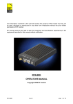
OPERATORS MANUAL
Copyright 2005 RF Central
RFX-PHT
LAST REV: 13 Dec 2006
Page 1 of 30
CONTENTS
1 GENERAL SAFETY INFORMATION...............................................................................4
1.1 Health & Safety ......................................................................................................5
1.2 Maximum RF Power Density Limits........................................................................6
2 INTRODUCTION .............................................................................................................7
2.1 GENERAL DESCRIPTION.....................................................................................7
2.2 RFX-CMT DESCRIPTION......................................................................................9
3 ACCESSORIES / OPTIONS..........................................................................................12
3.1 Vehicle Installation Kit ..........................................................................................12
3.2 Antenna Options...................................................................................................13
4 SPECIFICATIONS.........................................................................................................14
5 SYSTEM OPERATION ..................................................................................................15
5.1 Camera Interfaces................................................................................................15
5.2 Operator Controls / Menus ...................................................................................15
5.3 Initialization Menu.................................................................................................15
5.4 Main Menu............................................................................................................15
5.5 Ch / Frequency Menu ...........................................................................................18
5.6 Encoder Menu ......................................................................................................18
5.7 Audio 1 Menu .......................................................................................................18
5.8 Audio 2 Menu .......................................................................................................18
5.9 Status Menu .........................................................................................................19
5.10 Status Monitoring .................................................................................................19
5.11 System Configuration – Engineering Menu ..........................................................19
5.11.1 Prog Channels..............................................................................................19
5.11.2 FW Inventory ................................................................................................20
5.11.3 Video Input/Video Format.............................................................................20
5.11.4 Audio Input ...................................................................................................20
5.11.5 Temperature.................................................................................................20
6 PREPARING FOR OPERATION ...................................................................................21
6.1 EQUIPMENT PREPARATION .............................................................................21
6.1.1
Preparing Portable High Power Kit (PHT) ....................................................21
6.1.2
Preparing Camera-Mount Configuration (CMT)............................................21
6.1.3
The Receiving Equipment ............................................................................22
7 Connector Pin Outs .......................................................................................................23
7.1 SDI / CVBS Video BNC ........................................................................................23
7.2 Video Connector...................................................................................................23
7.3 Audio Connector...................................................................................................23
7.4 Power Connector..................................................................................................23
7.5 Remote Connector ...............................................................................................24
8 Module Descriptions ......................................................................................................25
8.1 Block diagram.......................................................................................................25
8.2 Audio / Video Encoder..........................................................................................26
8.3 COFDM Modulator ...............................................................................................27
Power Amplifier ..............................................................................................................27
8.4 Front Panel...........................................................................................................28
RFX-PHT
LAST REV: 13 Dec 2006
Page 2 of 30
9 Appendix A: MPEG Encoder Parameter Sets...............................................................29
10Appendix B: Table of DVB-T non-hierarchical bit rates..................................................30
RFX-PHT
LAST REV: 13 Dec 2006
Page 3 of 30
1 GENERAL SAFETY INFORMATION
The information that follows, together with local site regulations, should be studied by
personnel concerned with the operation or maintenance of the equipment, to ensure
awareness of potential hazards.
WARNING- RF Power Hazard: High levels of RF power are present in the unit. Exposure to
RF or microwave power can cause burns and may be harmful to health.
Switch off supplies before removing covers or disconnecting any RF cables, and before
inspecting damaged cables or antennas.
Avoid standing in front of high gain antennas (such as a dish) and never look into the open
end of a waveguide or cable where RF power may be present.
Users are strongly recommended to return any equipment that requires RF servicing to RF
Central.
WARNING- GaAs / BeO Hazard: Certain components inside the equipment contain Gallium
Arsenide and Beryllium Oxide that are toxic substances. Whilst safe to handle under normal
circumstances, individual components must not be cut, broken apart, incinerated or
chemically processed. In the case of Beryllium Oxide, a white ceramic material, the principal
hazard is from the dust or fumes, which are carcinogenic if ingested, inhaled or entering
damaged skin.
Please consult your local authority before disposing of these components.
CAUTION- Tantalum Capacitors: When subjected to reverse or excess forward voltage,
ripple current or temperature these components may rupture and could potentially cause
personal injury.
CAUTION: This system contains MOS devices. Electro-Static Discharge (ESD) precautions
should be employed to prevent accidental damage.
The information contained in this manual remains the property of RF Central and may not be used, disclosed, or reproduced
in any other form without the prior written permission of RF Central.
RF Central reserves the right to alter the equipment and specification appertaining to the equipment described in this manual
without notification.
RFX-PHT
LAST REV: 13 Dec 2006
Page 4 of 30
1.1
Health & Safety
Exposure to Non Ionizing (RF) Radiation/Safe Working Distances
The safe working distance from a transmitting antenna may be calculated from the
relationship:
D=
√
PT. GR
4π.w
In which D = safe working distance (meters)
PT = transmitter or combiner power output (watts)
GR = antenna gain ratio = anti log (gain dBi ÷10)
w = power density (watts/square meter)
The RF power density value is determined by reference to safety guidelines for exposure of
the human body to non-ionizing radiation. It is important to note that the guidelines adopted
differ throughout the world and are from time-to-time re-issued with revised guidelines. For
RF Central use, a maximum power density limit of 1w/m² is to be applied when calculating
minimum safe working distances. Appendix A refers.
Important Note: It must be remembered that any transmitting equipment radiating power at
frequencies of 100 KHz and higher, has the potential to produce thermal and athermal effects
upon the human body.
To be safe:
a)
Operators should not stand or walk in front of any antenna, nor should they allow
anyone else to do so.
b)
Operators should not operate any RF transmitter or power amplifier with any of its
covers removed, nor should they allow anyone else to do so.
Worked examples
Antenna
Type
OMNI
HELIX
PARABOLIC
DISH
Transmitter Power
Gain (dBi) Gain Ratio 2W
4W
4
2.5
1
1
20
100
4
5.6
35
3,162
22.5
32
10W
1.5
9
50
30W
2.5
15.5
87
MINIMUM SAFE DISTANCE (METERS)
RFX-PHT
LAST REV: 13 Dec 2006
Page 5 of 30
1.2
Maximum RF Power Density Limits
The RF Radiation Power Density limit figure recommended by RF Central is based upon
guideline levels published in:
a.
IEEE standard C95.1 1999 - IEEE Standard for Safety Levels with respect to Human
Exposure to Radio Frequency Electromagnetic Fields, 3 kHz to 300 GHz.
b.
Guidelines for Limiting Exposure to Time-varying Electric, Magnetic & Electromagnetic
Fields (up to 300 GHz) published in 1998 by the Secretariat of the International Commission
on Non-Ionizing Radiation Protection (ICNIRP).
Both documents define guideline RF power density limits for "Controlled" and "Uncontrolled"
environments. An uncontrolled environment is defined as one in which the person subjected
to the RF radiation may be unaware of and has no control over the radiation energy received.
The uncontrolled environment conditions can arise, even in the best regulated operations and
for this reason the limits defined for the uncontrolled environment have been assumed for the
RF Central recommended limit.
Documents a) and b) also show the RF power density guidelines to be frequency dependent.
Different power density / frequency characteristics are presented in the two documents. To
avoid complexity and to avoid areas of uncertainty, RF Central recommends the use of a
single power density limit across the frequency range 100 kHz to 300 GHz. The 1w/m² power
density limit we recommend satisfies the most stringent of the guidelines published to date.
Footnote:
The IICNIRP document may be freely downloaded from the internet at
www.icnirp.de/documents/emfgdl.pdf (PDF file)
RFX-PHT
LAST REV: 13 Dec 2006
Page 6 of 30
2 INTRODUCTION
2.1
GENERAL DESCRIPTION
Designed to utilize the RFX-CMT, the RFX-PHT portable 2 GHz digital transmitter comes with
either 5 or 10 watt max. power output. It provides a means to make any “news car” into a “live
car”. “Run and shoot” vehicles now become “run and transmit” The PHT can also be used in a
standalone mode for temporary transmit application. RF Central warranties the PHT for 3
Years.
This manual is to be used in conjunction with the RFX-PHT unit, which is composed of two
major components; the RFX-CMT and the Amplifier case.
Various optional accessories are available for the PHT described in detail in paragraph 2.3.
(fig. 2-1) – PHT Case (top view)
(fig. 2-2) – PHT Case (standing)
(fig. 2-3) – PHT Case (opened with CMT installed)
(fig. 2-4) – PHT Case (opened with CMT unclipped)
RFX-PHT
LAST REV: 13 Dec 2006
Page 7 of 30
(fig. 2-5)
Video In
Audio #1 Input
Remote Control
Amplifier Output
(to antenna)
Power In
(12 VDC at 12.5 Amps)
(fig. 2-7)
(fig. 2-6)
Audio #2 Input
(Yellow LED)
(Red LED)
Transmitter-to-Amplifier
Jumper
(Green LED)
(fig. 2-8)
(fig. 2-9)
RFX-PHT
Control Panel
RFX-PHT
LAST REV: 13 Dec 2006
Page 8 of 30
2.2
RFX-CMT DESCRIPTION
The core transmission component of the RFX-PHT is the RFX-CMT.
The RFX-CMT Wireless Camera system is designed for all applications, both indoor and
outdoor, in which a mobile camera is essential to the televised program production. The
RFX-CMT simply clips onto the battery adapter plate, transforming a standard news gathering
camera into a wireless camera.
The CMT system is comprised of the transmitter that contains an audio encoder, video
encoder, COFDM modulator, power supplies and an RF power amplifier. In its CMT
configuration, it is attached directly to a camera with an omni-directional antenna (see
diagram 2-1 & 2-2).
CMT Inputs
Audio In
Audio In
(connected)
Alternative Power
Supply In
(fig. 2-10)
RFX-PHT
(fig. 2-11)
LAST REV: 13 Dec 2006
Page 9 of 30
Switchable
Component / Composite
Video
Switchable SDI/CVBS
Input
(fig. 2-12)
RFX-PHT
SDI/CVBS Input cable
connected
(fig. 2-13)
LAST REV: 13 Dec 2006
Page 10 of 30
Typical RFX-CMT mounting configuration
(diagram 2-1)
External Views of the RFX-CMT
POWER
AMPLIFIER
RF OUTPUT
(diagram 2-2)
RFX-PHT
LAST REV: 13 Dec 2006
Page 11 of 30
3 ACCESSORIES / OPTIONS
3.1
Vehicle Installation Kit
The RFX-PHT Vehicle Installation Kit includes a mounting plate which secures the RFX-PHT
carry case in place, a magnetic mounted rooftop omni-directional antenna, and DC power
cable for vehicle battery power. Additional options are shown in table 2-1, below.
RFX-PHTMT
PHT Vehicle Mounting Plate
RFX-MAM
Magnetic Antenna Mount
3 strong 5-inch diameter magnets
RFX-RRM
Roof Rack Antenna Mount
Quickly & easily clamps to standard roof rack
RFX-OMNI-4.5
4.5 dBi Omni Antenna
9” long, 1 ¾” diameter, N-type male connector
RFX-AT8
8 dBi Omni Antenna
RFX-PHT unit mounted in vehicle
24” long, ¾” diameter, N-type male connector
RFX-WCM
POV Camera Suction Cup
Windshield Mount
RFX-PHTPS
PHT Power Supply
110 VAC input, 12 VDC output
RFX-CCK
Complete PHT Vehicle Wiring Kit
Power, Video, Audio, Remote switch, & Antenna Cables
Table 2-1
RFX-PHT
LAST REV: 13 Dec 2006
Page 12 of 30
3.2
Antenna Options
Antenna options for the RFX-PHT system vary based on a number of considerations. The
transmit and receive ends of the link can be considered separately, since each application is
unique.
Omni-directional antennas are typically used with the RFX-PHT link.
However, some
applications allow for more directional solutions, providing more robust transmission to the
receiver. Directional antennas are typically used when higher gain is required and can be
utilized in a variety of ways, from GPS auto-tracking to human control, or simple directional
pointing.
Receive antennas used with the RFX-PHT can be either Omni or Directional. For improved
receive system performance, diversity reception can be used with an array of multiple
antennas. RF Central’s diversity receiver technology uses maximum ratio combining to pull
together the output of all the antennas providing extremely robust / exceptional / exponentially
more reception.
Contact RF Central for more specific antenna information.
RFX-PHT
LAST REV: 13 Dec 2006
Page 13 of 30
4 SPECIFICATIONS
Frequency Band
Tuning Range /
Frequency Selection
Transmit Power
Skirts
RFX-PHT
1.990 - 2.500 GHz
To accommodate FCC channel plans; up to 16
pre-set channels, tuning in 0.5 MHz steps,
selectable via control panel
Adjustable to 5 Watts (higher power available
– contact RFC)
-30 db typical at 5 Watts
Modulation
Modulation Modes
COFDM DVB-T (2k carrier)
Data Rate
4.98 to 31.7 Mbit/s
Bandwidth
8MHZ, 7MHz, and 6MHz
Encoding Options
Video Input
MPEG 2: 4:2:0/4:2:2 (DVB standard)
Digital: SDI 270 Mbit/s
Analog: NTSC/PAL composite or component
Audio Input
2 x analog inputs, mic/line selectable
Power Requirements
12VDC (12 Amps)
110VAC Power Supply available
Size
14 x 10.5 x 6.5 inches
Weight
Environment
15.5 lbs
Temperature: -4° to +122° degrees F
Altitude: 14,500 ft
Humidity: 95% long term
QPSK, 16 QAM, 64 QAM FEC: 1/2 2/3 3/4 5/6
7/8 Guard interval: 1/4 1/8 1/16 1/32
LAST REV: 13 Dec 2006
Page 14 of 30
5 SYSTEM OPERATION
The following operation detail is specific to the RFX-CMT transmitter module of the RFX-PHT.
5.1 Camera Interfaces
The RFX-CMT transmission module of the RFX-PHT can be supplied with one of two battery
and camera interfaces:
• Sony ‘V’ Block / IDX
• Anton Bauer Gold Mount
These provide a flexible and versatile mounting system suitable for a wide range of cameras
and battery options.
The RFX-CMT is first mounted onto the camera rear battery interface. If required, an
appropriate battery can then be docked onto the rear of the RFX-CMT transmitter. The video
and audio cables must then be connected between the camera and the RFX-CMT, see 5.11.3
and 5.11.4 for details of the hardware configuration via the Control Panel.
If a battery is docked onto the rear of the RFX-CMT, no external DC power lead is required.
A separate lead is only required if a battery belt or external power supply is used.
Care should be taken to prevent damage to an external power supply if a battery is docked,
since current can be taken FROM the Power Connector.
5.2 Operator Controls / Menus
The RFX-CMT is configured using an LCD display and six push buttons. These are arranged
as four navigation buttons (▲▼◄►), Enter and Clear.
The Enter button is used to store the modified parameter in non-volatile memory; this
parameter will then be used to configure the RFX-CMT and will also become the default value
when next powered on.
The Cancel button can be used to exit a menu without storing the parameter in memory.
Various menu levels are provided to allow the operator to access the different hardware and
operating parameters:
5.3 Initialization Menu
At switch on the status of the initialization is displayed. If any errors are found with the
initialization of the major functions; Video, Audio, Encoder and Modulator; an error message
will be displayed. During initialization the Status LED will be off.
5.4 Main Menu
This is the display screen during normal operation of the RFX-CMT and indicates the TX
frequency, Channel number (or Manual frequency) and the current Encoder memory settings.
The ▲▼ buttons are used to select the required sub-menus; Ch/Freq, Encoder, Audio1,
Audio2 and Status, the Enter button is then used to select. The ◄► buttons are used to
display the current operational state.
During normal operation the Status LED will be green indicating ‘healthy’ state of the RFXCMT.
RFX-PHT
LAST REV: 13 Dec 2006
Page 15 of 30
RFX-PHT
LAST REV: 13 Dec 2006
Page 16 of 30
RFX-PHT
LAST REV: 13 Dec 2006
Page 17 of 30
5.5
Ch / Frequency Menu
This menu is used to select one of the sixteen pre-programmed channels (CH1 – Ch16) or
‘manual’ frequency selection. The ‘Man’ setting allows control of the transmit frequency in
0.5MHz steps within preset limits (0.5MHz steps are applicable to this version of the
transmitter; earlier versions have 1MHz steps).
The Enter button allows the ◄► buttons to select the required digit, the ▲▼ buttons then
select the required value. The Enter button then stores the value and returns to the Main
menu.
5.6 Encoder Menu
Using the ▲▼ buttons, this menu is used to select the required MPEG encoder operating
parameters. These are held in sixteen non-volatile memories (0 – 15). The ◄► buttons are
used to display for the selected memory:Modulation mode
Code rate
Guard interval
Data rate
- QPSK, 16QAM, 64QAM
- 1/2, 2/3, 3/4, 5/6, 7/8
- 1/32, 1/16, 1/8, ¼
- 4.976471 to 31.668449 Mbit/s
The encoder menu also selects the MPEG profile; 4.2.2, 4.2.0 and SP@ML (low delay)
Pre-programmed encoder parameter sets can vary according to individual customer
requirements; a separate sheet is included in the documentation accompanying the
equipment when shipped from the factory. As a guide, a typical set of 16 pre-set parameters
is included in Appendix A – Section 9
5.7 Audio 1 Menu
The Audio menus are split into two levels: Select Input and Set Level. The ▲▼ buttons and
Enter are used to select the required audio sub menu. The audio input can be set for either
Line or Mic input; selecting Mic gives a fixed +20dB gain.
There is also a level adjustment providing a +/- 20dB adjustment in 0.5dB steps. This level
adjustment is intended to cater for variations in camera audio output levels; it is NOT intended
to use these adjustments to set microphone sound level. It is assumed that the mic pre-amp
and limiter within the camera is used for this purpose.
5.8 Audio 2 Menu
As 5.7 above but for setting the Audio 2 input and level.
RFX-PHT
LAST REV: 13 Dec 2006
Page 18 of 30
5.9 Status Menu
The status menu is used to confirm the condition of the RFX-CMT. If the Status LED is red
indicating a fault or warning, the Status menu will indicate the nature of the problem.
The ▲▼ buttons are used to scroll through the various functions:
Video Input
TS Present
TS Rate
Synth Locked
PA Enabled/Disabled
RF Output
- a valid video input is present
- the MPEG encoder is generating Transport Stream
- TS data rate matches the modulator data rate
- the RF synthesizer is locked to correct frequency
- the RF PA is powered or disabled
- greater than +14dBm is present on the output
5.10 Status Monitoring
There is a red/green ‘status’ LED indicating the condition of the RFX-CMT , if a fault or
warning exists the LED will indicate Red and the Status menu will indicate the nature of the
fault / warning. During initialization of the unit the Status LED will be off.
The Status LED is capable of flashing RED to indicate a warning, or flashing GREEN to
indicate no video input. This is due to:
GREEN
No Video Input.
Check the camera is switched on and the video lead is
correctly connected
RED
The PA is turned off.
To disable the RF Power Amplifier the C and ◄ are
pressed as the RFX-CMT is switched on. This allows
the transmit frequency to be checked before the PA is
switched on. The PA can be re-enabled by re-cycling
the power.
5.11 System Configuration – Engineering Menu
The Engineering menu provides the method of hardware configuration. No user adjustments
or setup is provided internally.
The engineering menu is entered by pressing the ◄ and ‘C’ buttons simultaneously for
~10seconds, then releasing the ‘C’ button.
5.11.1 Prog Channels
Each of the sixteen frequency channels can be independently allocated the required
frequency with 0.5MHz resolution.
The ▲▼ buttons are used to select the Channel to be assigned. The Enter button then
allows the four ▲▼◄► to edit the required frequency. The Enter button then stores the
value and returns to the Main menu.
RFX-PHT
LAST REV: 13 Dec 2006
Page 19 of 30
5.11.2 FW Inventory
The firmware version for the encoder and main unit controller can be obtained from this menu
5.11.3 Video Input/Video Format
The RFX-CMT can accept either CVBS, YC, YUV inputs in either PAL (625) or NTSC (525)
via the six pin LEMO Video input connector or can be set to generate internal test bar
patterns of 75%, 100% or alternating between these two.
SDI digital video can also be input via the BNC 75Ω connector if required this can also be
used to input CVBS analog video.
Note: The CVBS LEMO input (Pin 1 & 2) is paralleled with the BNC input when CVBS is
selected; only connect to either one of these inputs or an incorrect signal level may result.
Signal routing is managed by the controller according to the selected options.
The ▲▼ buttons are used to select the required video input type. The Enter button then
stores the value and returns to the Main menu.
5.11.4 Audio Input
The RFX-CMT can accept two mono/one stereo analog input(s) via the five pin LEMO Audio
input connector or can be set to generate internal test tones of either 0dBFS or –18dBFS.
Signal routing is managed by the controller according to the selected options.
The ▲▼ buttons are used to select the required audio input type. The Enter button then
stores the value and returns to the Main menu.
5.11.5 Temperature
Provides a display of the internal temperature of the RFX-CMT controller in degrees Celsius
RFX-PHT
LAST REV: 13 Dec 2006
Page 20 of 30
6 PREPARING FOR OPERATION
6.1
EQUIPMENT PREPARATION
6.1.1 Preparing Portable High Power Kit (PHT)
Before leaving to undertake an operation it is recommended that the following equipment
checks be made.
Check that the CMT is securely fastened to the PHT unit.
Confirm that the vehicle-mounted bracket is secured properly to the vehicle.
Confirm that the PHT is properly secured in the vehicle-mounting bracket.
Confirm that all wiring is in good condition with no sharp bends or kinks.
Confirm antenna is mounted correctly and that antenna cable is properly connected.
Confirm external power cables are connected and secure.
Confirm the correct frequency is selected 5.5.
Confirm the correct preset mode of operation is selected. 5.6
Confirm the correct Audio level is selected 5.7
Confirm the correct Video input type is selected. 5.11.3
6.1.2 Preparing Camera-Mount Configuration (CMT)
Check that the Camera Adapter is securely fastened to the camera.
Check that the batteries to be used are fully charged and that an emergency spare battery is
available and fully charged.
Confirm the correct frequency is selected 5.5.
Confirm the correct Encoder mode of operation is selected. 5.6
Confirm the correct Audio level is selected 5.7
Confirm the correct Video input type is selected. 5.11.3
RFX-PHT
LAST REV: 13 Dec 2006
Page 21 of 30
If the camera is to be used with a cable-connected antenna, ensure that the cable is in good
condition, paying particular attention to the quality of the end connectors and their assembly
status. If extension cables are required, make sure that the cable connectors are compatible
or that the necessary back-back connectors are to hand.
To enable the frequency to be checked without transmitting RF power the RFX-CMT can be
powered up with the Power Amplifier disabled. To disable the RF Power Amplifier the C and
◄ are pressed and held as the RFX-CMT is switched on.
6.1.3 The Receiving Equipment
The transmitter may operate in conjunction with a variety of RF Central receivers, including
the RFX-PMR, RFX-RMR, and the RFX-MVRX. Contact RF Central for additional receiver
options.
When used with the RFX-CMT transmitter the receiving equipment produces two audio
channels, analog (mono), and one (stereo) AES3; - the third and fourth audios are nonfunctioning when used with either the RFX-CMT or the RFX-PHT. Video outputs include SDI,
composite video, and ASI output. If extension cables are necessary, ensure that the
connectors are compatible and of good quality to avoid problems at site.
Check that the receiving antenna/Receiver interfaces are clean and free from dust and other
unwanted materials.
If tripods are to be used to mount the equipment, make sure that some means of securing the
tripod or of weighting it down is provided. Gusty wind conditions may put installations at risk,
particularly when parabolic antenna dishes are to be used.
Make sure that all batteries, if used, are fully charged and whenever possible, provide a spare
with the cable to connect it to the Receiver.
Check that the Receiver channel frequencies are compatible with those of the RFX-CMT
Transmitter and set the channel selector switch to the channel number required. The
Receiver is labeled with channel number and frequency information. As a precaution, set the
manually selectable frequency of the Receiver to the working frequency.
Whenever practical, set up the system and trial it before leaving for site to ensure that
all components of the system are working. Checking at base, where adjustments and
corrective actions can be made, will pay off when setting up at site.
RFX-PHT
LAST REV: 13 Dec 2006
Page 22 of 30
7 Connector Pin Outs
7.1
SDI / CVBS Video BNC
SDI or composite video, blanking & sync (CVBS) input. Switched via controller dependant
upon Video Input Selection. See 5.11.3
75Ω BNC connector
7.2
Video Connector
Composite (CVBS) / YC / YUV
6Pin Lemo Plug FGG.1B.306.CLAD62Z
Pin
1
2
3
4
5
6
7.3
CVBS
0V
CVBS
YC
Y(0v)
Y
C(0v)
C
YUV
Y(0v)
Y
U(0v)
U
V(0v)
V
Audio Connector
Line / Mic Hi Z
5-Pin Lemo Plug FGG.1B.305.CLAD62Z
Pin
1
2
3
4
5
7.4
Function
0V (Screen)
Ch1 +
Ch1 Ch2 +
Ch2 -
Power Connector
9-18V DC 18W (power only)
This connector can be used to take power from the docked battery (5A Max) to power
external cameras if the RFX-CMT is not docked directly to the camera, or feed power into the
RFX-CMT and then forward into the camera.
RFX-PHT
LAST REV: 13 Dec 2006
Page 23 of 30
Note: A diode is fitted to prevent the external power supply from ‘back feeding’ into the
battery.
The power switch is used to control the RFX-CMT only. The power supply to the camera is
always available from the battery interface or external power connector. The camera on/off
switch should therefore be used to control the camera independently.
4 Pin Lemo Plug FGG.1B.304.CLAD62Z
Pin
1
2
3
4
7.5
Function
0V
0V
+12V
+12V
Remote Connector
RS232. 19200 Baud, 8 bit, 1 stop, No parity
4 Pin Lemo Plug FGG.0B.304.CLAD62Z
Pin
1
2
3
4
RFX-PHT
Function
0V
Tx (Data out from unit)
Rx (Data into unit)
0V
LAST REV: 13 Dec 2006
Page 24 of 30
8 Module Descriptions
The RFX-CMT is based upon the highly successful dock-able Wireless Camera system.
Internally, it is very different!
Factory engineers have completely redesigned the RFX-CMT to compress all the circuitry
from five circuit boards onto two. This greatly reduces space and weight compared with the
original wireless product.
The result is a Digital Wireless Camera system, which has exceptional RF performance, is
well-balanced and easy to use.
The RFX-CMT contains four circuit board assemblies:
•
•
•
•
Audio / Video Encoder
COFDM Modulator
RF Power Amplifier
Display / System Controller
PBAB-TDAV-0301
PBAB-TDVM-0303
PBAB-TDPA-0801
PBAB-TDDB-0101
The superior RF performance of the RFX-CMT when combined with an RF Central receiver is
such that it typically requires only a single receive point with Fan beam antenna for most
normal OB locations, including sports stadiums.
8.1
Block diagram
Control Panel
Analog
Audio 1
Analog
to AES3 AES3
converter
Analog
Audio 2
MPEG
Encoder
COFDM
Modulator
Power
Amplifier
Audio Input
AES
Video Input
CVBS, YC,YUV, SDI
Clip-On Block Diagram
RFX-PHT
LAST REV: 13 Dec 2006
Page 25 of 30
8.2
Audio / Video Encoder
The Encoder board consists of the following main functions:
•
SDI to Digital deserializer. Converts the SMPTE-259M-C serial digital video input
to an 8 bit parallel digital video bus.
•
Analog to Digital Video Converter, 10-bit over sampling ADC. Takes either
Composite Video (75 Ω, 1v p-p) (CVBS); YC or YUV inputs in either PAL / NTSC
format or converts to an 8-bit parallel digital video bus.
•
Analog to Digital Audio Converter, 48kHz, 24 bit
Two high impedance analog inputs. Audio 1 (or left channel). Audio 2 (or right
channel). The two channels are first buffered by a variable gain stage to cater for
either Mic or Line level inputs. A switchable 20dB stage is also included to cater for
low level Mic inputs. The two audio channels are then converted into an I2S serial
data stream.
•
FPGA. Selects the required 8 bit-parallel digital video bus from either the SDI
deserializer or the video ADC for input to the MPEG2 encoder. A relay is used to
route the input from the BNC (either SDI or CVBS) to either the deserializer or
ADC. Selects the I2S from the ASE/EBU receiver or the audio ADC for input to the
MPEG2 encoder. Generates the video test bars and audio test tones.
•
Microcontroller. Writes control data and reads status data to/from the MPEG2
Encoder.
•
MPEG2 Encoder
A suite of MPEG2 compliant compression techniques, where the data bit rate is
reduced by processing over multiple picture frames. The absolute picture (Intra
frame) is interleaved with pictures that are created using difference data (Predicted
frame) with Bi-directionally predicted frames (4:2:2 Only) in conjunction with motion
compensation; thus low data rates down to 6 Mbps, can be achieved.
A set of encoding parameters is loaded into the encoder at power up. These are
selected from one of the ‘preset’ encoder memories. See 5.6
•
DC Power Supplies
Switching DC/DC converters are used to generate the various supplies from the
incoming 9-18V battery supply. These include 2.5, 3.3V, 5V, 8V and +/-5V
supplies.
There are no field replaceable parts on the Encoder board. If a fault occurs with the board,
contact RF Central for technical assistance.
RFX-PHT
LAST REV: 13 Dec 2006
Page 26 of 30
8.3
COFDM Modulator
The acronym COFDM stands for “Coded Orthogonal Frequency Division Multiplexing – a
modulation scheme which is used by the DVB digital television system.”
The COFDM modulator has been designed to take its input from the MPEG2 encoder. This
Transport stream is then modulated directly to the 2/2.5/3.5/4.5GHz band as appropriate. This
method reduces the occurrence of intermodulated harmonic frequencies and requires less
up-converters to reduce microphony.
The COFDM modulator RF output is via the SMB connector. This output is then fed into the
power amplifier, via the short RF cable. The nominal RF output level is –9dBm of the
Modulator.
The modulator is automatically configured to match the data rate of the MPEG2 Encoder.
The modulator can support modulation schemes and data rates according to the chart in
Appendix B – section 10; operationally the modulator is configured according to preset
parameter sets as described in 5.6
There are no field replaceable parts on the COFDM modulator. If a fault occurs with the
board please contact RF Central for technical assistance.
Power Amplifier
The function of the power amplifier is to amplify the signal from the COFDM modulator to a
suitable level for transmission via the N-type connector into the antenna. The amplifier is
required to be highly linear to accommodate the multiple carrier signal formats employed for
digital system operation, with very low distortion (low intermodulation between carriers). The
nominal output power is +20dBm (100mW) across the 2/2.5/3.5GHz band (as appropriate).
Nominal overall gain is 29dB, thus the nominal RF input level is –9dBm. The amplifier
operates from a single +8 Volt supply. Nominal operational supply current is 700mA.
The status of the PA is provided by LEDs to monitor RF output level (green) and DC present
(red) and also monitored by the main controller and displayed as the status monitoring menu.
See 5.10.
To ensure good RF practice when power is applied to the RFX-CMT Camera back, always
make sure that there is a suitable load or antenna connected to the RF output.
RFX-PHT
LAST REV: 13 Dec 2006
Page 27 of 30
8.4
Front Panel
The Front Panel consists of a micro-controller, 16-character by 2-line LCD display, operator
switches and interface circuits (see fig. 7:1).
The Front Panel is the main system controller for the unit. All configuration of the unit
hardware is from this board. An I2C two-wire interface is used to communicate with all other
intelligent devices within the unit. This carries the command data and reads back status data
from all boards within the unit. At power-up this board initializes all the other boards and
during normal operation monitors all the major functions and reports any problems as part of
the unit status.
All configuration parameters, video settings, audio settings, MPEG encoder parameters,
frequencies etc are held on this board. The MPEG parameter set required (one of sixteen) is
selected via the Front Panel by the operator. These parameter sets are held in the nonvolatile memory of the front panel unit and can only be upgraded by the factory.
(fig. 7:1)
RFX-PHT
LAST REV: 13 Dec 2006
Page 28 of 30
9 Appendix A: MPEG Encoder Parameter Sets
Note: The following parameters are typical for the transmitter and are issued for guidance
only. Some transmitters may have different configurations according to individual customer
requirements.
Set
Part Number
Rate
(Mbit/s)
COFDM
Mode
MPEG
0
PBSW-TDVP0303-05-00
PBSW-TDVP0303-05-01
PBSW-TDVP0303-05-02
PBSW-TDVP0303-05-03
PBSW-TDVP0303-05-04
PBSW-TDVP0303-05-05
PBSW-TDVP0303-05-06
PBSW-TDVP0303-05-07
18.096257
64-QAM,
1/2, 1/32
64-QAM,
1/2, 1/32
64-QAM,
1/2, 1/32
64-QAM,
1/2, 1/32
QPSK
3/4, 1/32
QPSK
3/4, 1/32
QPSK
1/2, 1/32
QPSK
1/2, 1/32
422P@ML,
GOP4
SP@ML,
Infinite GOP
MP@ML,
GOP4
SP@ML, Infinite
GOP, Intra-slice
422P@ML,
GOP4
SP@ML, Infinite
GOP, Intra-slice
SP@ML,
Infinite GOP
MP@ML,
GOP4
1
2
3
4
5
6
7
RFX-PHT
18.096257
12.06417
12.06417
9.048128
9.048128
6.032086
6.032086
LAST REV: 13 Dec 2006
Video
Rate
(Mbit/)
16.59
Video
LPF
No
Low
Delay
Mode
No
Audio
Rate
(kbit/)
192
11.81
No
Yes
192
10.00
Yes
No
192
8.00
Yes
Yes
160
7.79
Yes
No
192
6.00
Yes
Yes
192
4.94
Yes
No
128
4.94
Yes
No
192
Page 29 of 30
10 Appendix B: Table of DVB-T non-hierarchical bit
rates
Modulation Code rate
QPSK
1/2
2/3
3/4
5/6
7/8
16-QAM
1/2
2/3
3/4
5/6
7/8
1/32
12.1
16.1
18.1
20.1
21.1
1/16
11.7
15.6
17.6
19.5
20.5
1/8
11.1
14.7
16.6
18.4
19.4
1/4
9.95
13.3
14.9
16.6
17.4
1/2
2/3
3/4
5/6
7/8
1/32
18.1
24.1
27.1
30.2
31.7
1/16
17.6
23.4
26.3
29.3
30.7
1/8
16.6
22.1
24.9
27.6
29.0
1/4
14.9
19.9
22.4
24.9
26.1
64-QAM
RFX-PHT
Bit rate (Mbit/s)
at each guard interval (symbol fraction)
1/32
1/16
1/8
1/4
6.03
5.85
5.53
4.98
8.04
7.81
7.37
6.64
9.05
8.78
8.29
7.46
10.1
9.76
9.22
8.29
10.6
10.2
9.68
8.71
LAST REV: 13 Dec 2006
Page 30 of 30