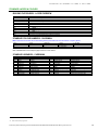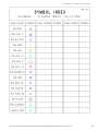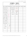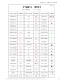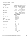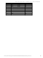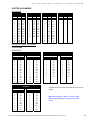
1
CADM OPERATORS MANUAL Prepared by Facilities Records, Infrastructure (Property) and Statewide Facilities Records for The University of Adelaide Level 12, Schulz Building North Terrace Adelaide SA 5000 TRIM No. D2011 / 23174 - CADM Operators Manual.doc - 23 February 2015 TABLE OF CONTENTS Table of Contents SERVICE PROVISION ....................................................................................................................................................... 6 FORWARD.......................................................................................................................................................................... 7 INTRODUCTION ................................................................................................................................................................ 7 SYSTEM................................................................................................................................................................ 10 CADM DIRECTIONS – HARDWARE ............................................................................................................................. 11 SERVER 11 SOFTWARE...................................................................................................................................................................... 11 CADM 11 SPACE 11 DOCUMENTS 11 CADM DATABASE MAINTENANCE ............................................................................................................................. 11 BACKING UP 11 Back Up & Recovery 11 HOUSEKEEPING - WITHIN CADDSMAN 11 New Buildings 11 Renaming Databases 11 Entity-Pack 11 Dab-Purge 12 DRAWING PRACTICE 12 Save regularly 12 CADM SYSTEM DATA STORAGE STRUCTURE........................................................................................................ 12 CADM (Caddsman) SYSTEM SETTINGS.................................................................................................................... 13 Installation 13 Settings Folders 13 System Setup 13 CAMPUS AND BUILDING NAMES: CHANGING OR ADDING .................................................................................. 13 POLICY: DRAWING REVISION AND DRAWING RETIREMENT ............................................................................... 13 DATAVIEWER – Watchfolder ........................................................................................................................................ 14 DIGITAL DATA received – K:\digital data received\ ................................................................................................... 14 DIGITAL DATA ARCHIVED – K:\digital data ARCHIVED\.......................................................................................... 14 DIGITAL DATA for cadm input – K:\cad_INPUT\ ........................................................................................................ 14 DRAWING............................................................................................................................................................. 15 CADM DATABASE – CREATION .................................................................................................................................. 16 NEW BUILDINGS 16 DIRECTIONS FOR THE INPUT OF FLOOR LAYOUTS 16 Special Detail Notes: ................................................................................................................................................... 16 Data Recovery Notes: ................................................................................................................................................. 16 ROOM NUMBERING 16 TITLE BLOCKS 17 REPAIR MISSING LINK ERRORS ................................................................................................................................. 17 METHOD 17 Addendum: Long File Names 18 STANDARD LAYERS & COLOURS .............................................................................................................................. 19 BUILDING FLOOR/LEVEL - LAYER OVERVIEW 19 STANDARD COLOUR NUMBERS - CADDSMAN 19 STANDARD LIBRARIES – CADDSMAN 19 CADM BUILDING LEVEL – LAYER DETAILS ............................................................................................................. 20 CADM STRUCTURE OF BUILDING FLOORS/LEVELS 20 CADM STRUCTURE OF SITE – SYMBOLS ................................................................................................................. 22 CADM STRUCTURE OF SERVICES – MODELS ......................................................................................................... 22 CADM STRUCTURE OF MAPPING GRID MODELS ................................................................................................... 22 CADM STRUCTURE OF SITE – MODELS.................................................................................................................... 23 S:\Services_Resources\Property_Services\Shared\FacRecords\CADM Manual\CADM Operators Manual_2015-02-23.doc 1 TABLE OF CONTENTS CADM STRUCTURE OF NORTH TERRACE SITE MODEL – to be applied to all sites ......................................... 24 Drawing identification nomenclature ........................................................................................................................... 33 Drawing Number convention 33 Campus Identifiers 33 Abbreviations for defined services, or disciplines, used for document numbers 33 DRAWING REVISION MAINTENANCE 33 CADM DRAWING INDEX GUIDE ................................................................................................................................... 33 Purpose ........................................................................................................................................................................ 33 ONE OFF DIGITAL DRAWINGS .................................................................................................................................... 34 Procedure for their Issue 34 CHECK LIST FOR DRAWING CHANGES .................................................................................................................... 34 Instructions ................................................................................................................................................................... 34 CHECKLIST – DEMOLISHED/SOLD BUILDING.......................................................................................................... 34 CADM System ............................................................................................................................................................. 34 CONTACTS FOR INFORMATION TO DRAWINGS – (ALL TYPES) .......................................................................... 35 CONTACTS FOR INFORMATION AND AMENDMENTS 35 PROCEDURE FOR UPDATING ..................................................................................................................................... 36 ELECTRICAL CADM DRAWINGS 36 LIGHT, POWER AND COMMUNICATION 36 HARD COPY DRAWINGS 36 FIRE BLOCK DRAWINGS 36 POLICY ........................................................................................................................................................................ 36 IRRIGATION DRAWINGS 38 CLEANING DRAWINGS 38 Standard Cleaning Drawing Legend .......................................................................................................................... 38 INSTRUCTIONS 38 LIQUOR LICENSING DRAWINGS 38 Standard LIQUOR LICENsING Drawing Legend...................................................................................................... 39 INSTRUCTIONS 39 SECURITY LIGHTING DRAWINGS 39 CHECKLIST 39 SECURITY ACCESS PLANS 40 UNDERGROUND SERVICES DRAWINGS (UGS) 42 ISOLATING VALVES IN BUILDINGS FOR MAINTENANCE 43 ISOLATING VALVES FOR PLAN RECIPIENTS (NORTH TERRACE CAMPUS) 43 DESIGN – Modelling for NEW WORK .......................................................................................................................... 44 PLOTMANAGER.............................................................................................................................................................. 44 TRANSFORMATION – How to and when to use ........................................................................................................ 44 ESSENTIAL SAFETY PROVISIONS (ESP) ....................................................................................................... 45 DATA MAINTENANCE .................................................................................................................................................... 46 SITE ESP REPORTS 46 APPLICATION (APPL PROGRAM) MAINTENANCE AND ALTERATIONS 46 ESP DRAWINGS 46 SYMBOLS ............................................................................................................................................................ 47 SYMBOL LIBRARY ......................................................................................................................................................... 48 HOW TO OPERATE & MAINTAIN SYMBOL LIBRARY 48 SYMBOLS - Creating detailed for a service 48 PLOTTING, PRINTING & STORING .................................................................................................................. 77 PLOTTING & PRINTING.................................................................................................................................................. 78 DRAWING PRODUCTION – GENERAL 78 SEQUENCE FOR PLOTTING 78 COMPOSING A DRAWING FOR A PLOT. 79 A1 COLOUR PLOTTER (Was for HP 750C) 79 STANDARD DRAWING LAYOUTS 81 SET UP FOR PLOTTING A1 DRAWINGS REDUCED TO A3 OR AN A1 SHEET 81 PEN WEIGHTS ........................................................................................................................................................... 81 ACCESS CONTROL DRAWINGS 82 S:\Services_Resources\Property_Services\Shared\FacRecords\CADM Manual\CADM Operators Manual_2015-02-23.doc 2 TABLE OF CONTENTS PEN WEIGHTS ........................................................................................................................................................... 82 CLEANING (FLOOR SURFACE) DRAWINGS 82 PEN WEIGHTS ........................................................................................................................................................... 82 REGISTERED FACILITIES DRAWINGS 82 LIQUOR LICENSING DRAWINGS 82 OCCUPANCY & CLEANING DRAWINGS 83 TITLE BLOCKS 83 TO CONVERT DRAWINGS TO A PDF (portable document format) FILE. (This requires Acrobat Professional) 83 SURFACE MAINTENANCE PROFILE DRAWINGS 83 PEN WEIGHTS ........................................................................................................................................................... 83 ELECTRICAL DRAWINGS 85 PEN WEIGHTS ........................................................................................................................................................... 85 ELECTRICAL SCHEMATIC DRAWINGS................................................................................................................. 85 PEN WEIGHTS ........................................................................................................................................................... 85 ESSENTIAL SAFETY PROVISIONS (ESP) DRAWINGS 86 COLLECTIVE DRAWINGS 86 PEN WEIGHTS ........................................................................................................................................................... 86 UNIQUE DRAWING DETAILS 87 LECTURE THEATRE SEATING LAYOUT DRAWINGS 87 PEN WEIGHTS ........................................................................................................................................................... 87 SECURITY LIGHTING DRAWINGS 87 PEN WEIGHTS ........................................................................................................................................................... 87 UNDERGROUND SERVICES DRAWINGS 88 PEN WEIGHTS ........................................................................................................................................................... 88 To Plot in Colour VIA HP-T1100ps 88 PLOTTING TO A NON-STANDARD SHEET SIZE 88 AUSTRALIAN STANDARDS SHEET OFFSETS (EXTRACT OF SAA H2 – 1975) 89 DATAVIEWER ...................................................................................................................................................... 91 DATAVIEWER .................................................................................................................................................................. 92 IMPORTING NEW DOCUMENTS 92 IMPORT DATA 92 Method ......................................................................................................................................................................... 92 COPY DOCUMENT FILES TO DATAVIEWER SERVER 92 LINKS INDEX TO DOCUMENTS (CHANGE LOCATION) 92 Method ......................................................................................................................................................................... 92 Options ......................................................................................................................................................................... 93 HELPFUL HINTS TO ASSIST IN TRACKING WHAT IS BEING DONE 93 Checking Data ............................................................................................................................................................. 93 Log Files....................................................................................................................................................................... 93 DRAWING UPDATES FROM WATCH FOLDER WITH MACRO 94 Operating and Maintenance Manuals .......................................................................................................................... 94 SPACE INVENTORY MANAGEMENT & PLANNING....................................................................................... 95 INVENTORY (CADM SPINV) .............................................................................................................................. 97 CADM - SPACE INVENTORY SYSTEM (SPINV) ......................................................................................................... 98 MODELLER SPACE MENU (Space ID) 98 INSERTING ROOM PLANES 98 AREAS TO BE SURFACED 98 TO TAG ROOM PLANES 99 TO CHANGE TAGS 99 TO CHANGE MULTIPLE TAGS 100 SELECT CAMPUS 100 EXPORT DATA FILE GENERATION 100 TAGGING MENU SYSTEM 100 CREATION OF MENU.TXT 101 CHANGES TO MENU.TXT FILE 101 S:\Services_Resources\Property_Services\Shared\FacRecords\CADM Manual\CADM Operators Manual_2015-02-23.doc 3 TABLE OF CONTENTS VITAL 101 STANDARD METHOD OF MEASURING BUILDING AREAS................................................................................... 102 Deductions ................................................................................................................................................................. 102 CHECKLIST - DEMOLISHED BUILDING .................................................................................................................... 103 CADM System 103 Dataviewer 103 SAM database (Refer to the SAM manual for full details) 103 Required report updates from SAM (Refer to the SAM manual for full details) 103 History Maintenance 103 SPATIAL ASSET MANAGEMENT (SAM) ...................................................................................................... 105 SAM ................................................................................................................................................................................. 106 Process 106 SAM 106 DATA EXCHANGE STANDARDS.................................................................................................................... 107 DATA EXCHANGE STANDARDS................................................................................................................................ 108 DOCUMENTATION 108 CADM 108 COMPUTER GENERATED MODELS AND DRAWINGS 108 DATA BASES 108 SYMBOLS (BLOCKS) 108 POLYLINES (STRING CURVES) 108 LAYER NAMES 108 EXCHANGE MEDIA 108 CADDSMAN 2004 .......................................................................................................................................................... 109 CREATING DXF’S, DWG’S & ISSUE TO EXTERNAL ORGANISATIONS 109 WRITING A DXF/DWG FILE 109 READING A DXF OR DWG FILE 109 WRITING DWG’S 109 FILE NAMING, STORAGE & ISSUE 109 Name.......................................................................................................................................................................... 109 Storage And Attachments ......................................................................................................................................... 109 Issue ........................................................................................................................................................................... 109 INSTRUCTION NOTES FOR AUTO CAD.................................................................................................................... 110 AutoCAD2000i 110 WRITING A DXF FILE 110 OPENING A DXF FILE 110 EXTERNAL REFERENCES- AutoCAD 110 XREF MANAGER 110 LIST OF EXTERNAL REFERENCES 110 INSERTING AN XREF FILE 110 CREATING PATHS FOR XREF FILES 110 CHANGING THE PATHS OF XREFS 111 CHARACTERISTICS OF OVERLAY XREFS: 111 CHARACTERISTICS OF ATTACHED XREFS: 111 BINDING XREF’S 111 RELOADING XREF 111 APPLYING DRAWING TO PAPER: 111 SWITCHING TO PAPER SPACE 112 TO MAKE A VIEWPORT, CONFIGURE AND SCALE IS AS FOLLOWS. 112 PAGE SETUP 112 CUSTOM SHAPE VIEWPORTS 112 ORGANISED LAYOUTS 112 TITLE BLOCKS (DRAWING SHEETS) 112 Inserting A Block Recommended ............................................................................................................................. 112 LOCKING THE VIEWPORTS 113 LINETYPES & PAPER SPACE 113 Aligning Objects that are in Separate Viewports 113 Working with the Layouts – Multiple Drawings Sheets 113 S:\Services_Resources\Property_Services\Shared\FacRecords\CADM Manual\CADM Operators Manual_2015-02-23.doc 4 TABLE OF CONTENTS RENAMING ............................................................................................................................................................... 113 MOVING OR COPYING ........................................................................................................................................... 113 USER TIPS ......................................................................................................................................................... 115 SYMBOLS GRIDS NEW LINE STYLES S:\Services_Resources\Property_Services\Shared\FacRecords\CADM Manual\CADM Operators Manual_2015-02-23.doc 116 116 116 5 S:\Services_Resources\Property_Services\Shared\FacRecords\CADM Manual\CADM Operators Manual_2015-02-23.doc 6 —SERVICE PROVISION SERVICE PROVISION This document forms part of the Consultancy Service Agreement (CSA) between the University and Statewide Facility Records recorded against TRIM number 2005/2838 Statewide Facilities Records are to provide the following services: Trained and experienced Caddsman/AutoCAD drafting personnel whose responsibilities include the following: Collect, assess and compile digital data/documents identified as required for maintenance in to the CADM system. This includes: The necessary review of hardcopy and softcopy documents using software tools such as Caddsman, AutoCAD, Acrobat, MS Word, Excel, Powerpoint and Access The contacting of contractors and consultants to acquire missing or incomplete documents or electronic documents Liaising with The University of Adelaide staff and external commercial consultants to determine relevant information relating to record requirements. Indexing all relevant documents to the DvTDM system and ensuring the record details are updated. Liaise with Scan Conversion Service staff to ensure all CADM sourced documents are correctly linked and indexed in the DvTDM system. Ensure this document, CADM Operators Manual is developed and maintained to reflect changes in the procedures and standards being employed for the maintenance of the CADM records and any changes in hardware systems being employed by Adelaide University. Provide first line support to users of the information systems with on-site staff. This includes: users of the DvTDM (Dataviewer) system Supply digital data to internal and external consultants in response to official requests. These may be by email or verbal (either telephone or face to face discussion) System technical documentation is maintained and technical issues are identified and elevated to support staff as required. Statewide Facilities Records will additionally provide on request: Additional support staff as requested by Adelaide University from time to time. This is limited to staff with the ability to support the functions above with tasks such as document preparation and basic data capture. Off-site data manipulation not able to be programmed for action at The University of Adelaide work location. Other record and data maintenance tasks / projects as agreed between Facilities Records and Statewide Facilities Records and quoted accordingly. Statewide Facilities Records contact details: PH 8341 7888, FAX 8341 7999. Address:17 Magarey Street, Largs North SA 5016 FORWARD The University of Adelaide land and built asset management systems are for the recording of information for the purpose of maintaining the integrity of these assets. Processes in place have been developed and implemented for the ease of data and information transfer between users at all levels. These processes are continuously developing and evolving with changing business applications and technological developments, locally and worldwide. The current documented processes are a result of products, information and services provided to and by The University of Adelaide. Users of the information are required to ensure that the level of information provided remains at a high level of accuracy and reliability by using developed procedures. INTRODUCTION The purpose of this manual is to provide procedural and instruction information pertaining to all the CADM related activities, technical record retrieval and viewing performed and provided by Facilities Records group for The University of Adelaide. S:\Services_Resources\Property_Services\Shared\FacRecords\CADM Manual\CADM Operators Manual_2015-02-23.doc 7 —REVISION CONTROL REVISION CONTROL This section is to record the major revisions to the document. DATE REVISION DETAILS S:\Services_Resources\Property_Services\Shared\FacRecords\CADM Manual\CADM Operators Manual_2015-02-23.doc AUTHOR CHECKED 8 SYSTEM S:\Services_Resources\Property_Services\Shared\FacRecords\CADM Manual\CADM Operators Manual_2015-02-23.doc 10 SYSTEM—CADM DIRECTIONS – HARDWARE CADM DIRECTIONS – HARDWARE SERVER The CADM data storage location is S:\Services_Resources\Property_Services\Shared\FacRecords\CAD. This is the University server ‘farm’ disk array We have three networked CADM workstations, and a Dataviewer server with the above directory mapped as K:\ Backups are automated on the ‘farm’ every night but we also make weekly copies on to local machines. ADMCDV001, ADMCDV023 and ADMCDV010. These are run manually using a bat file to run XCOPY with various switches set. SOFTWARE CADM Caddsman Produced by: Spatial, PO Box 622, Ringwood VIC 3134, Phone: (03) 9870 9877 Email: mailto:[email protected] SPINV (Space ID) Produced by: Facilities Records. Maintained by: Bill Buchanan, Phone: 0412535068, Email mailto:[email protected] SPACE Spatial Asset Management (SAM) Owned and developed by: University of Adelaide Maintained by: GH Technologies Aust Pty Ltd., 22 Nile Street, Port Adelaide SA 5015, Ph 8447 2088 Email mailto:[email protected] DOCUMENTS DATAVIEWER Produced by: Practical Programs Pty Ltd, 7 Tucker St, Adelaide, SA 5000 , Ph 8227 0877 Email mailto:[email protected] CADM DATABASE MAINTENANCE BACKING UP Back Up & Recovery The university servers are backed up each night within the IT systems. Caddsman Recovery of files are to be first attempted by using the DBK files created when Caddsman opens a file. If this fails there are weekly backups made to ADMCDV001, ADMCDV023 and ADMCDV010. The latter is occasionally backed up to an external drive Only as a last resort call IT for a file recovery as this can take 48 hrs or more. HOUSEKEEPING - WITHIN CADDSMAN New Buildings If there is a need to add a new building to the CADM system a request has to be made to the Manager Facilities Records to add this building to SAM before CADM modelling is started. Renaming Databases Can be done at the system level using the normal Windows file rename features. Checking that all the drawings and links still work is essential as the links may break. Entity-Pack This should be run regularly on each file opened. It checks a file for integrity and cleans out unconnected elements S:\Services_Resources\Property_Services\Shared\FacRecords\CADM Manual\CADM Operators Manual_2015-02-23.doc 11 SYSTEM—CADM SYSTEM DATA STORAGE STRUCTURE Select File/Utilities/Entity-Pack Type in the file name for the data to be written to i.e. check file and select the file to be checked. Dab-Purge This should be run regularly on each DAB to consolidate and reduce their size as stored on disk. DRAWING PRACTICE Save regularly When using CAD databases, save your work regularly, e.g. every 5 to 15 minutes, and close the CAD programme down every hour and restart, to reduce/minimise the incidence of data loss. Only run one instance of CAD concurrently. CADM SYSTEM DATA STORAGE STRUCTURE SERVER Server – remote to working location (NETWORK cable route would be approx. 1km) NOVELL NETWARE v 5…… A folder is mapped as K:and holds all CADM DAB’s within directories indexed in Caddsman Modeller as libraries LOCAL PCs Local - Windows 2000 & NT4 Caddsman installed C:\Modeller 2004 is the + system library C:\Modeller 2004\User as the start-up dir. Directories as follows: DABs kept in each users system folder: Acc-cont architect archland cleaning comm_sfgs crests drgsheets elec-schm ESP fire_sfgs Accommodation Commercial F1-Martindale farm F2-Mundunney Farm F3-Morelana Farm F4-Charlick Farm F5-Glenthorne Farm field_stations FireBlockPlans Hospitals Land miscellaneous National_Wine_Centre projects Roseworthy spacecad sports-grounds StateMap Surveys thebarton waite irrigation LiqLic light_sfgs mechanical mech_sfgs power_sfgs Reg-Fac sewer sign-sfgs site-light survey trees ugs-lines A master set of symbols is stored on K:drive but is never called from the Caddsman program. It is the master store of the in case the local or users set is damaged or lost. All users have a set of SETTINGS.DEF files to enable allow the users to work locally on large DAB’s to speed up work and minimise the risk of damaging the DAB’s during the saving process These ‘local’ set of ‘settings’ and folders are to facilitate fast, efficient and convenient working on databases locally on their PC. To use this copy the DAB/s across the network to these folders (a copy of the structure on the server) and run the ‘local’ mapped settings file. Once work is finished, copy the DAB back to the server in to its original location, over writing the original. Plotmanager (Refer to the detailed section for complete information) This tool manages the production of drawings for indexing in to Dataviewer. Refer to the Dataviewer section for more specific details. S:\Services_Resources\Property_Services\Shared\FacRecords\CADM Manual\CADM Operators Manual_2015-02-23.doc 12 SYSTEM—CADM (CADDSMAN) SYSTEM SETTINGS CADM (Caddsman) SYSTEM SETTINGS Installation Install to C:\< Modeller xxx >, NOT ‘Program Files’ folder. Use the master settings file stored in K:\FR\CADD\CMAN-setup-for-each-machine\ to start with and build on that to suit the way you work. Master will need editing to match ‘+System” library Settings Folders User C:\Modeller SJ\User\ Settings C:\Modeller SJ\Settings\ Symbols C:\Modeller SJ\ System Setup Many of these settings are a personal preference though many assist in maintaining an environment that speeds the work and aids consistency, across all operators, with production. CAMPUS AND BUILDING NAMES: CHANGING OR ADDING Why: to align Facilities Records indexes and central systems for the listing of assets and thus reporting for assets and insurance. E.G. Possible new campus, commercial or city for the recording of buildings in the CBD. Easy in SAM, difficult elsewhere. Split buildings out of groups CADM and record individually. This to aid all auditing and reporting. Issues within: CADM Rename databases to new campus or building name Split buildings out of groups to individuals Build drawings as necessary Check existing drawings still work Edit building and drawing titles as necessary to reflect altered (new) names, etc NO REVISIONS to drawings Significant time and effort. Need to determine process and package for offsite work Dataviewer Rebuild Master lookup lists Re-index documents back to new list entries Edit any information relevant Extract drawing lists for importing to SAM – occupancy only Time and some difficulty SAM Rename campus Rename building Import drawings from Dataviewer lists Inter-relationship management Managing priorities for the changes and FR requirements POLICY: DRAWING REVISION AND DRAWING RETIREMENT Why: to control the version accessed and referenced for legal purposes, and after 26 revisions (the complete alphabet. E.G. Possible new campus, demolished building replaced with new facility. Etc. When drawing revisions commence at ‘A’ and reach ‘Z’ then the drawing number is retired. A new, next available drawing number will be issued at revision 0 noting the superseded drawing number Superseded drawing information shall be located in the first row of the amendment section E. G. ISSUE SUPERSCEDED No X-X-X-XX MTH/YR AMENDMENT DATE S:\Services_Resources\Property_Services\Shared\FacRecords\CADM Manual\CADM Operators Manual_2015-02-23.doc 13 SYSTEM—DATAVIEWER – WATCHFOLDER DATAVIEWER – WATCHFOLDER ALL OPERATORS In the interest of keeping the status of drawings in the *:\dataviewer\WatchFolder\ and K:\Digital_Data_Received clear to DV operators please make sure that folders are clearly labelled. If you are not going to index drawings yourself please move them into a folder in the root of *:\WatchFolder labelled with a short description of the job followed by "TO_BE_INDEXED". Please create a TXT file within the folder with any relevant information about the drawings ie, date, name of operator, which job, if revisions of existing drawings in DV etc. This also applies to any other files put into \WatchFolder and \Digital_Data_Received. As we have multiple people accessing these folders at different times it is important to leave notes in a TXT file so that others are aware of the status of files. All drawings in \WatchFolder in folders under an operators name are considered working files and not yet ready to be indexed by DV operators. DIGITAL DATA RECEIVED – K:\DIGITAL DATA RECEIVED\ ALL OPERATORS This area is dedicated to the storage of digital information for indexing in to Dataviewer. CADM operators are NOT to directly work with files stored here and should not access these files until the Dataviewer staff have moved them to k:\CAD_Input. This is so the knowledge is kept as it was sent to FR and does not get corrupted with FR’s handling processes. DIGITAL DATA ARCHIVED – K:\DIGITAL DATA ARCHIVED\ ALL OPERATORS This area is dedicated to the storage of digital information after the Dataviewer operations are completed for new information. CADM operators are NOT to work with files stored here and should not access these files unless there is a problem with files bey drawn from the K:\ CAD_input directory or there is a request for information that cannot be sourced else ware due to another problem. DIGITAL DATA FOR CADM INPUT – K:\CAD_INPUT\ This directory is the area where all files relevant for inputting in to the University CADM system are to be stored for initial access and during the work process of importing. Copying the files to a local directory is acceptable to speed initial processing, BUT, the original files MUST be deleted at the completion of the data transfer process and the master drawing issued within the Dataviewer system. S:\Services_Resources\Property_Services\Shared\FacRecords\CADM Manual\CADM Operators Manual_2015-02-23.doc 14 DRAWING S:\Services_Resources\Property_Services\Shared\FacRecords\CADM Manual\CADM Operators Manual_2015-02-23.doc 15 DRAWING—CADM DATABASE – CREATION CADM DATABASE – CREATION NEW BUILDINGS If a new building is required in the CADM system a request has to be made to the Manager Facilities Records to add this building to SAM before CADM modelling is started. This is to establish the correct building name and number for the generation of the campus library reference files for use within CADM. DIRECTIONS FOR THE INPUT OF FLOOR LAYOUTS Note: 1. 2. 3. 4. 5. 6. 7. 8. 9. 10. 11. 12. 13. 14. North is to the top of the screen. All building layouts are drawn 1:1 (full size) Always check the layer and colour prior to starting work, reset as necessary Select the icons and settings lower left corner of Caddsman. LAYER 999 is reserved for the largest projected plan outline of the building. The ORIGIN shall be (0,0,0) (North Terrace Campus only) and shall coincide with a point on the SITE SURVEY DRAWING S-119 and cross-referenced with drawings S-118, S-120 and S121. If, because the floor plan is taken at 1200 above finished floor level, the corner of the building is slightly different to the coordinates on drawing S-119 then this difference shall be noted on the CADM site plan, recorded on drawing S-119 print and on the LAYER 999 outline. COPY this outline to LAYER 0 for the production of the LOWEST LEVEL of the building. Add the internal features in accordance with the directions in BUILDING FLOOR/LEVEL LAYER OVERVIEW and the CADM STRUCTURE OF BUILDING FLOORS/LEVELS. Text – mil-std, height 350 width 275 Where buildings adjoin the common coordinates and wall dimensions shall be checked with the adjoining model outline on layer 999. This can be done in several ways a) check against the drawings in Dataviewer, and measure accordingly b) merge the two relevant models using either a common datum i.e. 000 or to a point you designate. Follow the directions in Caddsman. RL's shall be in CYAN (4) text on the layer of the building outline it represents. e.g. RL 40 140. Text height 500 width 400 Weight 0.25 Stair arrows and associated text shall be on the same layer as the building outline to which it relates. Title each level by placing the LEVEL NUMBER in RED, UPPER CASE and 500 x 400 in size where it will be plotted and easily read. Usually lower LHS of floor layout. Place all the text in the correct orientation for reproduction; this is usually - 90o or 0o. This allows the text is read from the left of the screen or normally. The requirement for this is historic and related to the general shape of the building and the ‘normal’ landscape orientation of drawings. Construct the drawing, save as a MODEL or SYMBOL. (create symbol) in the appropriate DATABASE file (Write symbol) i.e. !M8, 1 Place a BOUNDARY (PLOT/BOUNDARY) around that the model or figure. To do this have the model or symbol on the screen then select PLOT, then BOUNDARY then select a start point and drag a visual box to neatly surround the entities required. You may at this stage type in a PLOT SCALE for final PLOT though it can be changed during the PLACE phase later on and the effect can be viewed almost instantly as you place the VIEW on the screen's drawing sheet. Select FILE/SAVE or SAVE AS - This will save the MODEL or SYMBOL complete with the boundary. Using SAVE AS requires further user input as to location and name to be applied It is now safe to close Caddsman or close the current file and open another or start a new one. SPECIAL DETAIL NOTES: All surface planes added for walls, ducts, lifts, etc., identification shall be tagged with the IGNORE label within the SP Macros menu. Refer to the SPINV section for details on space occupancy plane TAGing. Data Recovery Notes: If there is a lost symbol (floor of building, etc) this may be recovered from the *.dbk file created when the database was last saved. If this fails the next step is to use the weekly backup on PSBCASUAL. Remember this is only a copy of status on the LAST Friday prior to the current day. As such it could be 6 days old. Read in the dab/symbol required and save AS to the correct DAB. ROOM NUMBERING The schema for the University is NOT the same for all buildings. The following will have to be adapted to suit the building being renumbered. The standard is to number space in all buildings from the lowest level up through the building. The space (room) number format reflects the level it is on and the sequence on the level. History often dictates the first character, e.g. B, LG G or 1 where B = Basement, LG = Lower Ground, G = Ground and 1 = Level One The first space number is the primary entry to the building or level. I.e. B00, LG00, G00 or 100. Corridors from this space are sub space numbers of this i.e. B00a, LG00a, G00a or 100a. Service risers off corridors also take a sub number off that corridor B00g, LG00g, G00g or 100g or of the room from which they are accessed eg 345a (level 3 space 45 a) Once the building level/floor has a designation of 10 then a space is inserted into the number to differentiate the level and space number i.e. 10 33a. S:\Services_Resources\Property_Services\Shared\FacRecords\CADM Manual\CADM Operators Manual_2015-02-23.doc 16 DRAWING—REPAIR MISSING LINK ERRORS If numbering is found to be illogical or not matching this ‘standard’, discussion with the users and Property Services management is required for resolution and door re-labelling costs etc. TITLE BLOCKS These are required to match the layer structure of the building and text layers in the building databases, described in DIRECTIONS FOR THE INPUT OF FLOOR PLANS and CADM STRUCTURE OF BUILDING FLOORS/LEVELS The STANDARD title block is maintained in the +SYSTEM library with in the drngsheets.DAB Read this model in to Caddsman and save AS a model called TITLE in to the related building database and as all text is pre formatted little alteration is required. As drawings have revisions recorded on them there may be a requirement move the revision list to an alternative location. There are 2 standard positions: Directly above the title block and immediately to the left of the title block. Revision Notes text size and weight should match the following if none is available to copy FONT HEIGHT WIDTH WEIGHT COLOUR TITLE FILLED 5 3.5 0.15 250 7 5.5 0.25 250 DRAW NO. FILLED REPAIR MISSING LINK ERRORS NOTE: This is the process of fixing Caddsman data files if the original AutoCAD files have NOT been fully ‘exploded’ before importing to Caddsman METHOD 1. 2. Open the Caddsman File which is reporting missing link errors. Take note of the EXACT file names which are missing, with attention to the difference between the number zero (0) and the letter O. The file name is case sensitive. Note – If the Caddsman file was created in an older version, long file names will not be able to be created. See addendum for instructions in this instance. 3. 4. 5. 6. 7. 8. 9. 10. 11. 12. 13. 14. 15. 16. 17. Ignore all to clear this error window, and close the file. Create a new Model, in the Database with the missing files. It’s not necessary to be in same Database, but makes managing the files easier. In the new Model, draw a Circle of diameter 20,000 (20m) in colour 2 with line weight set to 2. Insert to coordinate 0, 0, 0. This creates an easily recognisable entity to delete from the drawing later on. Add a text entry colour 2, weight 2, size 3000 Height, 2000 Wide to coordinate 0, 0, 0. Edit this text entity to a unique description of one of the missing link file names, e.g. *U00000000000017b7 may be identified with ‘17b7’. This allows you to identify which entities you are deleting from the drawing later on. Save the Model with the ‘Save As’ command in the affected Database as one of the missing files, e.g. *U00000000000017b7. Switch back to the new Model and change the text entry to another missing file name. e.g. ‘4C1F’. Save as the next file name, e.g. *U0000000000004C1F. Repeat Steps 6 & 7 until you have created a new Model for each file missing from the Database. Reopen the affected Symbol/Model file. This time, select each missing file as listed in turn, and click on change to redirect the file to Database containing the new one you have just created. Repeat for each file which is missing, and continue. If a file doesn’t change, you have not correctly entered the file name of the new file. You will need to reopen this file and use ‘Save As’ to create the correct file name. Change the view from TOP to BOTTOM or PAR. Don’t delete the Plot Boundary for Top as this may affect the Pen Settings in all the drawings. Turn on all Layers. Select “Make Visible in Current View” command, and select “Select All”. Select “Zoom Fit”. S:\Services_Resources\Property_Services\Shared\FacRecords\CADM Manual\CADM Operators Manual_2015-02-23.doc 17 DRAWING—REPAIR MISSING LINK ERRORS 18. 19. 20. 21. 22. 23. 24. 25. 26. 27. 28. You should now be able to easily identify the location of the ‘missing’ links as large circles, with large text entities within. The size of the circles may vary, depending upon the scale with which they had originally been inserted into the drawing. Delete these entities, taking note of each of the file name extensions you embedded as you go. This allows you to identify which files you have found and deleted. Run Application ‘Cha-pnt.ape’ to remove extraneous points from the drawing. Run Utility ‘Entity Pack’ to delete extraneous lines from the drawing. Run Utility ‘Check’ to check for extraneous entities. Save and Exit drawing. In the Caddsman file menu, select the ‘Delete’ command, and delete the models you created, marking off from the list of files you deleted from the Drawing. You should have deleted every new Model you created. If not, repeat Steps 11 to 23 to identify and locate every unwanted entity. The Database should now not have any unwanted files. Reopen the original file. If all goes well, you shouldn’t have any error window reporting missing files. Turn off all layers excepting the Walls and Text (0 & 1 or equivalent). Change view to top and ‘Zoom Fit’. Save & Exit. Addendum: Long File Names The schema for the University is NOT the same for all buildings. The following will have to be adapted to suit the building being renumbered In the situation where the missing link file name is very long, some DABs which were created in an older version of Caddsman will not allow you to create the full file name. In this instance, you will need to create a block with the full name in AutoCAD, insert this block into an AutoCAD drawing, and then read this AutoCAD drawing into Caddsman. Essentially, the process for this is the same as above. The main difference is that the 20m circle is created within AutoCAD rather than Caddsman a) b) c) d) e) f) g) h) i) j) k) l) m) n) o) p) q) r) s) t) Open a new drawing in AutoCAD. Draw a 20m diameter circle fixed to position 0,0 as in step 5 above. ‘Zoom All’ to see the full circle. Type command ‘wblock’ to create a block (link is the Caddsman term). Make base point 0 0 0. Click on select objects, and then select the circle edge. Right click to enter. Make sure ‘Convert to block’ option is selected. In Destination option, save the file name as the EXACT duplicate of the missing link file name. Click ‘OK’. You should see a preview window pop up briefly showing you a thumbnail image of the block you just created. Repeat steps d to h until you have created a block (link) for every file name that you need. Start a new drawing in AutoCAD. Type ‘Insert’ to insert the blocks you have just created. Use the browse option in the Insert Dialog Box to locate your first block. Leave Insertion Point, Scale and Rotation unchecked. Insert to 0 0 0, scale 1 1 1, and click OK. Zoom All to view the inserted block. Repeat Steps l to o until you have inserted at least one copy of each file name that you need. Save the drawing as a 2000 version and exit. Read the new AutoCAD file into Caddsman. Save and exit. This creates a DAB for you to link the missing file to as in step 12 above. S:\Services_Resources\Property_Services\Shared\FacRecords\CADM Manual\CADM Operators Manual_2015-02-23.doc 18 DRAWING—STANDARD LAYERS & COLOURS STANDARD LAYERS & COLOURS BUILDING FLOOR/LEVEL - LAYER OVERVIEW LAYER 0 50 100 150 200 250 300 350 400 998 999 CONTENT Level ONE of the building, basement or the lowest level or floor " TWO " " " " THREE of the building " FOUR " " " " FIVE " " " " SIX " " " " SEVEN " " " " EIGHT " " " " NINE " " " For insertion of Building grid lines Reserved for the largest projected plan outline of the building. STANDARD COLOUR NUMBERS - CADDSMAN Note: These colours are reserved for base building drawing information and not to be used for occupancy planes. 0 Red 5 Purple 10 1 Green 6 Brown 11 2 Dark Blue 7 Light Green 12 3 Yellow 8 Salmon 13 Light Yellow 4 Light Blue 9 White 14 Caddsman has 255 colours and each can be adjusted at will. This is NOT to be done with out discussion of the CADM group. Refer CADM Standard Colour Map two pages further on in this manual. STANDARD LIBRARIES – CADDSMAN SYM ! @ # ’ % ^ & + < LABEL North Terrace Waite Roseworthy Thebarton Nth Adel Field Stns Misc System Spare Sports Gnds FOLDER K:\north_terrace K:\waite K:\roseworthy K:\thebarton K:\north_adelaide K:\field_stations K:\miscellaneous C:\ Modeller 2004 K:\spare K:\sports-grounds SYM ? _ ( } ) * { > | = LABEL F1-Martindale F2-Mundunney F3-Moralana F4-Charlick F5-Glenthorn NWC Non_Collegiate_Housing Projects Hospitals Services FOLDER K:\F1-Martindale K:\F2-Mundunney K:\F3-Moralana K:\F4-Charlick K:\F5-Glenthorn K:\NWC K:\Non_Collegiate_Housing K:\projects K:\hospitals K:\north_terrace\services.dab i.e. there will be 50 layers per floor S:\Services_Resources\Property_Services\Shared\FacRecords\CADM Manual\CADM Operators Manual_2015-02-23.doc 19 DRAWING—CADM BUILDING LEVEL – LAYER DETAILS CADM BUILDING LEVEL – LAYER DETAILS CADM STRUCTURE OF BUILDING FLOORS/LEVELS Layer CONTENTS COLOUR Col. No. 0 External Walls Internal walls, solid & structural Internal partitions, doors, stairs, windows & projected lines (arches dashed style 1) Red Red Green (0) (0) (1) Fixed fittings, and furniture, etc, (except lecture seating) Adjoining building walls (only put in the exterior wall) Weight of ALL lines 0.1 - Direction arrows on stairs shall have a GREEN shaft with a 45° head in RED 500mm long. Text: room names, & functions, etc Room numbers, size & weight mil-std font, height 350, width 275, hor. space 0.05, weight 0.15 Reduced Levels (RL), height 500, width 400, hor. space 0.05, weight 0.25 Movable furniture, desks, seating, etc. Floor finishes (text) Power outlets (GPO's DB's etc.) IP Nos. Text mil-std font, 250 height x 175 width, weight 0.25 " " Cable Ducts - weight 0.7 Light layout and switching IP Nos. Text mil-std font, 250 height x 175 width, weight 0.25 Lighting circuit wiring Communications - Voice/Data Points, weight 0.25 IP Nos. Text mil-std font, 250 height x 175 width, weight 0.15 HVAC (Heating, Ventilating & Air Conditioning) Water Gas Sewer Storm Water Extra gasses etc Fire hydrant & hose reels. Wet (water) fire systems Sprinklers Col 7, Pipe work Col 2 & weight 0.25, Text 250 x 225 Col 2. Thermal detectors Computer Cabling - weight 0.7 Security Systems – Access Controls Ceiling Building Construction notes & revisions Teaching Space Audit Planes Usable Floor Area (UFA) planes – applied to each room Inside of wall surface (Ade Org Unit ID - AOU) Including vending machine lease areas - allow 500mm area in front of machines. Gross Floor Area plane & Gross Building Area plane & Nett Lettable Gross Floor & Building Area Perimeter lines Room Type Planes (intensity 0.4) CTA’s controller text (Occupants names used to be here) Exit & Emergency Lighting (Egress) & Lifts Compartmentation (Smoke/fire doors etc.) Fire Ratings (Pattern – Fire wall 100 or 300 USER scaled) WIPS, FIPS, MECP, Speakers etc. symbols Smoke Detectors Thermal & Smoke detector. Circuiting, MCP, etc Fire Dampers/Smoke Spill, duct heaters and fans Site Measured Spaces (is this still required?) Extinguishers Maintenance Access, hatches, etc. (weight 0.5) Fume Cupboards (Text 350 x 275) External door numbers Hazardous Areas - Radiation Source, Chemical, Laser, Biological, etc. Text – 250h x 175w, wt 0.15 Cleaning Floor Area planes. Colour to suit cleaning standards Text mil-std font, 800 height x 600 width, weight 0.35 Maintenance Lease identification Wall fill surface planes Liquor Licensing – Areas covered by the Licences Registered Facilities – Incl.- Quarantine, Radiation & PC3 Areas – Colour Intensity 0.75 The Legend is in the +System library – Reg-Fac.dab – model Legend Operator generated grid lines Largest projected outline plan Light Blue Light Yellow (4) (22) Light Yellow White Cyan Light Green White Brown/Yellow Light Green Purple Dark Blue Light Green Mid Blue D. Blue Purple Green Salmon D. Blue Select Colour TBA Salmon Light Green Salmon Light Green Light Green Cyan White Various Purple-lines Buff Blue (Tic) Purple Various White Purple Orange Brown Salmon Salmon Orange Yellow Orange D. Blue D. Blue Orange Yellow To suit White (13) (9) (4) (7) (9) (6)/(3) (7) (5)/(3) (2) (7) (17) (2) (5) (1) (8) (2) (8) (7) (8) (7) (7) (10) (9) 66, 68, 71, 77, 85 (5) (22) intensity 0.50 (4) (5) 21, 25, 26, 28, 29 (9) (5) (21) (6) (8) (8) (21) (3) (21) (2) (2) (21) (3) NA 34 TBA Green TBA (1) Quar – 27, Rad – 25, PC3 - 23 White Red Intensity 0.75 1 2 3 4 5 6 7 8 9 10 11 12 13 14 15 16 17 18 19 20 21 22 23 24 25 26 27 28 29 30 31 32 34 35 36 37 38 39 40 42 49 998 999 S:\Services_Resources\Property_Services\Shared\FacRecords\CADM Manual\CADM Operators Manual_2015-02-23.doc Style No. (14) (14) (9) (0) 20 DRAWING—CADM STRUCTURE OF SITE – SYMBOLS S:\Services_Resources\Property_Services\Shared\FacRecords\CADM Manual\CADM Operators Manual_2015-02-23.doc 21 DRAWING—CADM STRUCTURE OF SITE – SYMBOLS CADM STRUCTURE OF SITE – SYMBOLS Note: this is to be changed as we move to models for sites. This is a long-term exercise. This page does NOT apply to NORTH TERRACE or THEBARTON CAMPUS sites. See later section Note: North is to the TOP of the screen Scales are 1:1000 or 1:1m LAYER COLOUR NO Roads, Curbs, Major Paths Yellow 35 Adjoining Roads, Curbs, Major Paths White 57 Adjoining Buildings Lilac 56 Minor Paths Around Buildings Mauve 43 31 Road Text White 41 32 Buildings, Structures Red 32 33 Building Text White 41 34 Fences, Gates Light Blue 36 35 Gardens, Dams, Sloping Banks, Retaining Walls Green 33 36 Trees, FT SITE-SUB 30 CONTENTS Light Green 39 Text 40 Site Division Boundary Blue 2 99 Building Plans Grey 15 100 Building Zones Blue 34 37 CADM STRUCTURE OF SERVICES – MODELS Sub-note: Layer numbers in the form ‘1 12’ indicate that North Terrace Campus Site layer is 112 and other campuses are 12. LAYER CONTENTS COLOUR NO UGS 0 Symbol (SITE-SUB) 1 17 Underground Services Grid Reference White 9 1 18 Stormwater Dark Blue 2 1 19 Mains Water, Tanks Magenta 5 1 20 Sewer Salmon 8 1 21 Gas Green 1 1 22 ETSA Brown 6 1 23 Telecom, Computer Green 1 1 25 Fire Services (Water) Salmon 8 1 26 Sewer Neutraliser Pits Salmon 8 1 27 Irrigation Green 1 Irrigation (Electrical & Communication cabling) White 9 Light Blue 4 Salmon 8 COLOUR NO SEC-LIGHT 0 Symbol (SITE-SUB) 1 15 Security Lighting FIRE 0 Symbol (SITE-SUB) 1 24 Fire Services (Block Plan) CADM STRUCTURE OF MAPPING GRID MODELS LAYER CONTENTS 0 Boundary Mid Blue 13 1 Leader Olive 29 2 Text White 9 S:\Services_Resources\Property_Services\Shared\FacRecords\CADM Manual\CADM Operators Manual_2015-02-23.doc 22 DRAWING—CADM STRUCTURE OF SITE – MODELS Site models and symbols are currently documented using AMG coordinates. It is anticipated to migrate to the newer Australian mapping coordinates. GDA 94 (Geocentric Datum of Australia) and the MGA 94 (The Mapping grid of Australia) some time in the future. CADM STRUCTURE OF SITE – MODELS Sub-note: Layer numbers in the form ‘1 12’ indicate that North Terrace Campus Site layer is 112 and other campuses are 12. LAYER CONTENTS COLOUR NO Yellow Light Blue Salmon Green White Purple Light Green Salmon Salmon Red Light Blue Light Yellow Light Yellow Light Brown Magenta Blue T.B.A. Light Green Light Green Light Green 3 4 8 1 9 5 7 8 8 0 4 13 13 14 5 2 BOUNDARIES 0 0 1 2 3 4 Symbol (SITE-SUB) Roads and Division Boundaries Gross Planes for Owned Land Lot Area Planes for Owned Land Property Boundary Lines Lot Numbers Owned and Leased Other 5 6 7 10 11 15 16 17 20 21 30 40 41 42 Lot Area Planes Leased Areas Hundred Nos. Easements Fences - Main Property Boundary Fences – Internal Paddock Numbers Paddock Rotation No. Neighbour Name & Contact Nos. Water Mains Water Troughs & Valves Soil Types Vegetation – Native Vegetation - Introduced Vegetation - Noxious CARPARK 0 Symbol (SITE-SUB) 1 11 Car parking Lines Magenta 5 Car parking Numbers White 9 1 12 Traffic Flow Arrows Salmon 8 1 13 Handicapped Access Light Green 7 1 14 Road Signs and Text Light Green 7 1 15 Car parking Permit Layout 1 16 Road Surfaces Salmon 8 Off Road Surfaces - paving, grass etc Misc BLDG-INDEX 1 North Terrace Building Names for SITE PLAN Red 0 MISC 0 Symbols (SITE-SUB) 40 Building Reference Grid Red, White, Green 0,1,9 41 Waste Management Blue 50 42 Land Area Planes Orange 54 43 Contours, Spot Heights, Stations White 58 44 Building Area Planes Blue, Grey 50,51 45 Main Entrances to Buildings Mustard, Cream 53,54 46 Monuments & Art Work Dark Blue 2 S:\Services_Resources\Property_Services\Shared\FacRecords\CADM Manual\CADM Operators Manual_2015-02-23.doc 7 7 7 23 DRAWING—CADM STRUCTURE OF NORTH TERRACE SITE MODEL – TO BE APPLIED TO ALL SITES CADM STRUCTURE OF NORTH TERRACE SITE MODEL – TO BE APPLIED TO ALL SITES Note: This model is 3D, i.e. a survey with elevation. North is to the TOP of the screen. Scales are 1:1000 or 1:1m. Colour indicates general layers for site. These are to be left ON when saving the site LAYER 0 1 2 3 4 LAYER NAME Vacant AMG grid points Pm Pegs Property boundaries (lines/Easements) 5 6 7 8 9 Ct/folio nos. and lot nos. Contours minor Contours major Contour text Neighbouring sites buildings building text levels (buildings) pavers (text/levels) overhangs fences text (undetermined) features contoured surfaces text trees plaques Natural surface (lines) Natural surface (points & text) Natural surface triangulation NTH.TCE. ROAD LINES, MARKINGS, LEVELS Water (lines) Water (pts & text) Trees (pts & text) Spare Road (wt pts & text) Road (lines) road markings (lines) road levels road kerb levels road kerb levels Road (text) Concrete (lines) concrete (pts & text) pavers (lines) pavers (Pts & text) fences (rails & gates) fences (pts & text) wall (lines) wall (points & text) spare features (lines) features (points & text) spare bld. (lines) and shade sails Bld (points, text, FFL.) (Levels, sills, doors, etc) bld names bld surface stormwater (lines) stormwater (points & text) mains water (lines) mains water (points & text) fire main (lines) fire main (pts & text) sewer (lines) 10 11 12 13 14 15 16 17 18 19 20 21 22 23 24 25 26 27 28 29 30 31 32 33 34 35 36 37 38 39 40 41 42 43 COLOUR NAME l-green red brown green (NWC) BLUE/WHITE white dk-yellow magenta magenta mauve mauve white white white (Style 1) white white l-red grey white COLOUR No. COMMENTS 7 32 6 1/ (NWC) 49/75 9 53 5 5 green green 56 56 57 58 55 54 53 52 51 59 64 65 1 1 WHITE 56/57/58/59/65 dk-blue 2 green 1 yellow/white dk-yellow white white white white 3/9 28 59 62 61 60 l-grey l-grey dk-yellow yellow l-blue white red white 15 15 35 3 36 9 0 9 dk-blue dk-blue 27 79 red red/white mauve white red dk-blue dk-blue green orange pink pink pink 32 32/9 56 41 32 2 2 1 11 11 11 S:\Services_Resources\Property_Services\Shared\FacRecords\CADM Manual\CADM Operators Manual_2015-02-23.doc 24 DRAWING—CADM STRUCTURE OF NORTH TERRACE SITE MODEL – TO BE APPLIED TO ALL SITES 44 45 46 47 48 49 50 51 52 53 54 55 56 57 58 59 60 61 62 63 64 65 66 67 68 69 70 71 72 73 74 75 76 77 78 79 80 81 82 83 84 85 86 87 88 89 90 91 92 93 94 95 96 97 98 99 100 101 102 103 104 105 106 107 108 109 110 111 sewer (pts & text) electrical (Lines) electrical (points & text) sec lighting (lines) sec lighting (pts & text) gas (lines) gas (pts & text) communication (lines) communication (pts & text) signage signage (pts & text) waste management waste management (pts & text) spare unknown services Gen. purpose (lines) Gen. purpose (pts & text) furniture furniture Vines & Surrounds (Nwc) Creek (Nwc) tree legend and grid–OLD INFO (THEBARTON) Carparking Lines (THEBARTON) Carparking numbers (THEBARTON) traffic flow arrows handicapped access road signs and text Carparking permit layout road surfaces off road surfaces – paving grass etc pink salmon salmon l-blue l-blue green green green green l-green l-green/white 11 8 8 4 4 1 1 1 1 7 7/9 l-blue 4 l-grey white white dk-blue dk-blue/white LIGHT GREEN LIGHT BLUE / white 15 9 9 2 2/9 39 50/60 8,40 magenta WHITE salmon light green light green 5 9 8 7 7 BLUE misc 18 VARIOUS Light Green White 7 9 pattern layer site grid (50m x 50m) light grey white/yellow 15 9/3 Carparking Lines/Numbers VARIOUS 2/5/9/20/27 Security Cameras Security Camera text temporary frontage-Mitchell to Bonython S:\Services_Resources\Property_Services\Shared\FacRecords\CADM Manual\CADM Operators Manual_2015-02-23.doc 25 DRAWING—CADM STRUCTURE OF NORTH TERRACE SITE MODEL – TO BE APPLIED TO ALL SITES 112 113 114 115 116 117 118 119 120 121 122 123 124 125 126 127 128 129 130 131 132 133 134 135 136 137 138 139 140 141 142 143 144 145 146 147 148 149 150 151 152 153 154 155 156 157 158 159 160 161 162 163 164 165 166 167 168 169 170 171 172 173 174 Carparking Traffic Arrows/Handicapped Access Carparking Permit Layout Bicycle parking security lighting Tree Maintenance Numbers And Boundaries underground services grid reference underground services grid TEXT stormwater mains water, tanks sewer gas etsa telecom, computer fire services SITE – ( ESP ) fire services (water) sewer neutraliser pits irrigation irrigation (electrical & communication cabling) Information Common To 118-127 Oil Compressed Air SALMON VARIOUS 8 3/4/5/7/9/16 l-blue MID-BLUE / WHITE 4 59 / 49 White, AQUA dk-blue magenta salmon green brown green salmon salmon salmon green white 9 42 2 5 8 1 6 1 8 8 8 1 9 LIGHT GREEN LIGHT GREEN BROWN 7 7 6 asset identifiers - stormwater street catchment unknown services lilac sand 21 24 22 site grid (33.33m x 33.33m) white/green/red 9/1/0 “Boundaries” Model Layer Structure Property Boundary Points Property Boundary Points - Text Property Boundaries - External Property Boundaries – External – Text (Boundary Lengths, Angles) Property Boundaries - Internal Property Boundaries – Internal – Text (Boundary Lengths, Angles) Property Boundaries – Internal – Dashed Easements Easements – Text (Lengths, Angles) Certificate Of Title V & F (Adel Uni Allotments) Vacant Dp & Df Numbers Hundreds Numbers Allotment Numbers Section And Portion Numbers Title Surface - 1 Title Surface – 2 – Non Commercial Title Surface – 3 – Individual Allotments Street Names Street Property Numbers Vacant Property Boundaries - Adjoining Owners Property Boundaries - Adjoining Owners – Text (Boundary Lengths, Angles) Property Boundaries - Adjoining Owners – Certificate Of Title 46 71 70 63 70 65 63 63 63 64,63 63 84 39,46,84 58 68 83 70 37 S:\Services_Resources\Property_Services\Shared\FacRecords\CADM Manual\CADM Operators Manual_2015-02-23.doc 26 DRAWING—CADM STRUCTURE OF NORTH TERRACE SITE MODEL – TO BE APPLIED TO ALL SITES 175 176 177 178 179 180 181 182 183 184 185 186 187 188 189 190 191 192 193 194 195 196 197 198 199 200 201 202 203 204 205 206 207 208 209 210 211 212 213 214 215 216 217 218 219 220 221 222 223 224 225 226 227 Vol. & Folio Nos. Property Boundaries - Adjoining Owners – Ownership Details Property Boundaries - Fences Area Numbers Riverbank & Centreline Centreline Of Streets Vacant Vacant Vacant 71,63 37 Site Grid OLIVE, BR, L/GREEN, MAGENTA 3, 5, 6, 7 stormwater (site) Water (SITE) dk-blue purple/white 2 5/9 gas (site) ETSA (site) green brown 1 6 fire services (site) - ESP salmon 8 irrigation irrigation (electrical & communication cabling) green white 1 9 SURFACES LLSD hoarding Brick paving surfaces 228 229 230 231 232 233 234 235 236 237 238 239 S:\Services_Resources\Property_Services\Shared\FacRecords\CADM Manual\CADM Operators Manual_2015-02-23.doc 27 DRAWING—CADM STRUCTURE OF NORTH TERRACE SITE MODEL – TO BE APPLIED TO ALL SITES 240 241 242 243 244 245 246 247 248 249 250 251 252 253 254 255 256 257 258 259 260 261 262 263 264 265 266 267 268 269 270 271 272 273 274 275 276 277 278 279 280 281 282 283 284 285 286 287 288 289 290 291 292 293 294 295 296 297 298 299 300 301 302 303 304 305 Communication (site) Green 1 Signage Green 7 Buildings (verandahs etc) points and text Survey Grid points and text AMG Grid Points Pegs brown white white, green, red white light green brown 306 Site Grid (50mx50m) white, yellow 307 308 309 points and text Site Grid (33.33mx33.33m) points and text white white, green, red white 56 9 9,1,0 9 7 6 building lines 9,3 services grid 9 9,1,0 9 building grid survey set-out grid S:\Services_Resources\Property_Services\Shared\FacRecords\CADM Manual\CADM Operators Manual_2015-02-23.doc 28 DRAWING—CADM STRUCTURE OF NORTH TERRACE SITE MODEL – TO BE APPLIED TO ALL SITES 310 311 312 313 314 315 316 317 318 319 320 321 322 323 324 325 326 327 328 329 330 331 332 333 334 335 336 337 338 339 340 341 342 343 Barrier points and text Fences points and text RRWall points and text blue white light pink white red white 52 59 36 9 0 9 Stormwater UG Mains_Water UG Sewer UG Gas UG Electrical UG Communications (Intercom etc) UG Fire_Services UG Fuel UG Irrigation UG Unknown Services UG Cable Marker UG blue pink salmon green brown green salmon light green green yellow cyan 2 5 8 1 6 1 8 7 1 3 4 Drain points and text Waterways / wells points and text Waste points and text SEP points and text light pink white blue white cyan white blue white 24 9 2 9 4 9 27 9 Concrete points and text Roads/Driveway points and text light grey light grey dark grey white 15 15 19 9 344 Line marking yellow, white 345 346 347 348 349 350 351 352 353 354 355 356 357 358 points and text Paving/Footpath points and text Kerb/Water Table points and text Nat_Surf points and text Grass points and text Vegetation points and text Building Surface points and text Carpark/Arrows white light cyan yellow blue white brown white light green white green wh light green white salmon 53, 59 359 Permit Layout various 360 Features blue 27 361 362 363 364 365 366 367 368 369 370 371 points and text Signage points and text Doors points and text Windows points and text Lifts - Site points and text Security_Cam points and text white light green light green light cyan white light pink white dark pink white red red 9 7 7 10 9 11 9 16 9 0 0 9 10 3 2 9 6 9 7 9 1 9 32 9 8 3, 4, 5, 7, 9, 16 retaining walls This covers all types of fuel (oil, petrol, Diesel) services not identified side entry pits All linemarking carparking lines, traffic direction arrows, disabled access all permit information physical features not classified elsewhere, e.g. statues, fountains, furniture S:\Services_Resources\Property_Services\Shared\FacRecords\CADM Manual\CADM Operators Manual_2015-02-23.doc 29 DRAWING—CADM STRUCTURE OF NORTH TERRACE SITE MODEL – TO BE APPLIED TO ALL SITES 372 373 374 375 376 377 378 379 380 381 382 383 384 385 Lighting points and text cyan white Postal Service points and text Railway points and text Rubbish Bins points and text salmon salmon light grey light grey light green white 386 TS Audit Route Surfaces orange, light yellow, light green, light blue, pink 387 388 389 points and text white 390 Undefined light brown 22 391 points and text light brown 22 Contour - Major points and text Contour - Minor points and text Easement points and text Stairs points and text Spot_Heights 2D points and text Survey points and text Spot Heights 3D points and text pink pink yellow yellow orange orange light green light green blue blue light green light green green green 5 5 53 53 21 21 57 57 2 2 32 32 1 1 Surfaces – Maintenance Profiles Olive,Br,L/Grn,Mag Mains_Water AG Sewer AG Gas AG Electrical AG pink salmon green brown 5 8 1 6 423 Communications (Intercom etc) AG green 1 424 425 426 427 428 429 430 Fire_Services AG Fuel AG Irrigation AG Unknown Services AG Cable Marker AG salmon light green green yellow cyan 8 7 1 3 4 Neighbouring Sites brown brown 392 393 394 395 396 397 398 399 400 401 402 403 404 405 406 407 408 409 410 411 412 413 414 415 416 417 418 419 420 421 422 4 9 8 8 15 15 7 9 66, 68, 71, 77, 85 9 3,5,6,7 56 56 Points/items requiring definition Areas required for of cleaning and responsibility of sites buildings building text S:\Services_Resources\Property_Services\Shared\FacRecords\CADM Manual\CADM Operators Manual_2015-02-23.doc 30 DRAWING—CADM STRUCTURE OF NORTH TERRACE SITE MODEL – TO BE APPLIED TO ALL SITES light green salmon pink cyan yellow blue green white light green yellow light grey / to suit 57 58 55 54 53 52 51 59 51 53 15 431 432 433 434 435 436 437 438 439 440 441 442 443 444 445 446 447 448 449 Patterns 450 Boundaries' Model Layer Structure 451 Property Boundary Points 452 Property Boundary Points - Text 453 Property Boundaries - External 46 454 Property Boundaries - External - Text (Boundary Lengths, Angles) 71 455 Property Boundaries - Internal 70 456 Property Boundaries - Internal - Text (Boundary Lengths, Angles) 63 457 Property Boundaries - Internal - Dashed 70 458 Easements 65 459 Easements - Text (Lengths, Angles) 63 460 Certivicate Of Title V & F (Adel Uni Allotments) 63 461 462 463 464 465 466 Dp & Df Numbers Hundreds Numbers Allotment Numbers Section & Portion Numbers Title Surface - 1 467 Title Surface - 2 - Non Commercial 468 Title Surface - 3 - Individual Allotments 58 469 470 471 Street Names Street Property Numbers 68 83 472 Property Boundaries - Adjoining Owners 70 473 Property Boundaries - Adjoining Owners - Text (Boundary Lengths, Angles) levels (buildings) pavers (text/levels) overhangs fences text (undetermined) features contoured surfaces text trees plaques 63 64,63 63 84 39,46,84 S:\Services_Resources\Property_Services\Shared\FacRecords\CADM Manual\CADM Operators Manual_2015-02-23.doc 31 DRAWING—CADM STRUCTURE OF NORTH TERRACE SITE MODEL – TO BE APPLIED TO ALL SITES 474 Property Boundaries - Adjoining Owners Certificate Of Title Vol. & Folio Nos. 475 Property Boundaries - Adjoining Owners Ownership Details 476 Property Boundaries - Fences 477 478 479 480 481 482 483 484 485 486 487 488 489 490 491 492 493 494 495 496 497 498 499 Area Numbers Riverbank Centreline Centerline Of Streets 37 71,63 37 Site Grid S:\Services_Resources\Property_Services\Shared\FacRecords\CADM Manual\CADM Operators Manual_2015-02-23.doc 32 DRAWING—DRAWING IDENTIFICATION NOMENCLATURE DRAWING IDENTIFICATION NOMENCLATURE Drawing Number convention Campus N - Service A - Bld# D15 - No (in series) 118 - Revision A Campus Identifiers SYM N W R T NA FS MISC SG LABEL North Terrace Waite Roseworthy Thebarton Nth Adel Field Stns Misc Sports Gnds SYM F1 F2 F3 F4 F5 NWC NCH HOSP LABEL F1-Martindale F2-Mundunney F3-Moralana F4-Charlick F5-Glenthorn National Wine Centre Non_Collegiate_Housing Hospitals Abbreviations for defined services, or disciplines, used for document numbers Abbrv. Service or Discipline Abbrv. Service or Discipline AC ACCESS CONTROL L LIFTS A ARCHITECTURAL LT LAND TITLE C COMMUNICATIONS M MECHANICAL CVL CIVIL SITEWORKS O OCCUPANCY E ELECTRICAL P PLUMBING ESP ESSENTIAL SAFETY PROVISIONS RT ROOM TYPE F FIRE S STRUCTURAL FC FUME CUPBOARDS TS TEACHING SPACE AUDIT IRR IRRIGATION UGS UNDERGROUND SERVICES DRAWING REVISION MAINTENANCE This is part of the Title Block and the Drawing Number specifically and works in conjunction with Dataviewer. Read and understand the application and control of revision identification for drawings in conjunction with the process of Dataviewer and revision indexing. CADM DRAWING INDEX GUIDE Refer to – Dataviewer section for full detail on this facility Purpose To manage the revisions to drawings and provide WEB access to the images for ALL CADM maintained documents listed below and other one off unique issues: Access Control Irrigation Architectural Land Titles Mechanical Cleaning Communications Occupancy Electrical Plumbing Essential Safety Provisions (ESP) & Fire Underground Services (UGS) Fire Block Plans Other Fume Cupboards On creation of new drawings these are to be plotted to file and placed in the watch folders on the Dataviewer server. These will then be imported in to Dataviewer and indexed. Check that the drawing has gone in and indexed correctly with all relevant meta-data attached for searching and retrieval. S:\Services_Resources\Property_Services\Shared\FacRecords\CADM Manual\CADM Operators Manual_2015-02-23.doc 33 DRAWING—ONE OFF DIGITAL DRAWINGS Note: Dataviewer is also used to manage all scanned hardcopy and consultant provided digital documents in addition to the CADM documents listed above. For information on access to Dataviewer please contact The University of Adelaide, Space Planning, UniSpace :Ph 8313 0352 or Email [email protected] ONE OFF DIGITAL DRAWINGS Procedure for their Issue Hand annotate on the printed output OR electronically on the PDF that this information is produced as a unique representation and that an exact replica is NOT always possible. Write the following information, ‘what has been produced’, the date, by whom, the DAB name, symbol and layers used, on the product sent to the user so if another request is received for the same product it is possible to closely replicate the original. NOTE: One off drawings are NOT recorded on the systems and are therefore NOT maintained. FR is looking at a methodology to allow some form of retention for future reference, possibly using Dataviewer to hold a copy of the document produced. CHECK LIST FOR DRAWING CHANGES Instructions 1. 2. 3. 4. 5. 6. 7. 8. 9. Update architectural modifications i.e. walls, doors, windows, fixed furniture etc Update textural changes, i.e. room usage, room numbering etc Update floor and occupancy plans Update gross floor area (GFA) and gross building area GBA) planes Update title block Print to file (PLT and PDF) all documents required to Dataviewer watch folder and request them to be indexed. All prints are to be identified for electronic distribution from Dataviewer as required. Update Site plan / Building name databases and drawings where necessary Notify Manager Facilities Records of Site plan changes. i.e. new buildings, demolished buildings, site work, change of building names etc. Repeat this process for all other drawing types as required. Policy Note: ESP & FBP Drawings When updating Architectural information within and around buildings the FB Plans need to be reviewed in relationship to those building changes. Any possible discrepancies are required to be brought to the attention of FR Management and an appropriate response directed back to the provider of the amended information. A response time frame should be issued to complete the task and update all FBP information as required for that building and for the adjoining site. Refer to the detailed sections for more complete details and explanation per service type. CHECKLIST – DEMOLISHED/SOLD BUILDING CADM System 1. 2. 3. On advice that ALL corrections to Architectural, Services & Site data bases are done, e.g. services isolation - Double check that the real situation is recorded. Remove the *.DBK file for the building or create a new one if only partially demolished. Advise ALL hardcopy plan holders of the building removal. Note: Refer to Checklist – Demolished Building. This is only part of the process; refer to INVENTORY and SAM section later in this manual for the complete process description. S:\Services_Resources\Property_Services\Shared\FacRecords\CADM Manual\CADM Operators Manual_2015-02-23.doc 34 DRAWING—CONTACTS FOR INFORMATION TO DRAWINGS – (ALL TYPES) CONTACTS FOR INFORMATION TO DRAWINGS – (ALL TYPES) All contacts are listed here to assist in chasing relevant information for the maintenance of drawings and documents related to Facilities Records requirements. It is the responsibility of the contact to maintain any local hardcopy of the plans they require via Dataviewer & local printing facilities. CONTACTS FOR INFORMATION AND AMENDMENTS POSITION Supervisor Maintenance Service Centre ITS Network Specialist ITS Co-ordinator Locksmith Manager Security Manager OH & S ADDRESS Oliphant, G17 CONTACT (Kinghorne A) PHONE 34008 9 Gawler Place, Level 9 9 Gawler Place, Level 9 Security, Hughes Plaza Office Hughes Plaza Office 115 Grenfell St., 13th Flr (Muller H) (O’Daly I) (Botterill P) (Joseph M) (TBA) 35590 35984 35878 34034 COMMERCIAL Building Managers – Colliers Direct service call 1300 550 106 (Vella, David) 83038004 ROSEWORTHY Site Co-ordinator Campus Manager Main Building (D1) Main Building (D1) (Beck J) (Forwood D) 37848 37816 THEBARTON Facilities Manager Building 29 – Gaskell (Evans & Ayers) (Cossich, Eric) 0407008961 WAITE Campus Manager Hartley House (10b) (Brokenshire A) 37217 NATIONAL WINE CENTRE Events Sales Coordinator George Murray (Strong-law S) 33077 Waite Building (Charlick Exper Stn) Mortlock (Martindale) - Manager (Moralana Station) (Lake Torrens) (Munduney Station) (Glenthorne Farm) (Harris D) (Bidstrup I) 0407979797 FIELD STATIONS School Manager Administrator Officer Physics & Maths – Physics Bldg Environmental Biology-Benham (Maelzer C) (Brown C) 35113 34695 HOSPITALS Exec Officer Health Sciences Level 1 Medical school North (Mathews S) 33859 (Mylius S) (Chester G) 35879 33015 (Kinghorne A) (Joseph M) (Maddigan S) (Rochler F) 34008 34034 35151 35814 FARMING Discipline Manager - Ag&Wine Martindale Holdings P/L SPORTS GROUNDS Manager Parks & Grounds – Oliphant Bldg Executive Office Sports Association – Lady Symon Bldg THEATRE SEATING PLAN RECIPIENTS MSC Supervisor Oliphant, (G17) Security Manager Security- Hughes Plaza Office Facilities Bookings Union House-George Murray Timetable Co-ordinator Wills (L8), Rm 640 SCOTT & UNION HALLS ONLY Theatre Co-ordinator Union Hall/Scott Theatre (Dennie J) 33620 ESSENTIAL SAFETY PROVISIONS MSC Supervisor Tyco Inc/Wormalds – W,T & R Tyco Inc/Wormalds – Nth Tce [email protected] [email protected] (A Battifuco) (D O’Donnell) (K Mills) 0402838976 0421054041 TEACHING SPACES Timetable Co-ordinator Facilities Bookings Wills (L8), Rm 640 Union House-George Murray (Rochler F) (Maddigan S) 35814 35151 S:\Services_Resources\Property_Services\Shared\FacRecords\CADM Manual\CADM Operators Manual_2015-02-23.doc 35 DRAWING—PROCEDURE FOR UPDATING PROCEDURE FOR UPDATING ELECTRICAL CADM DRAWINGS LIGHT, POWER AND COMMUNICATION Alterations to drawings are provided by the electrical maintenance contractor via the MSC, Information Technology Service (ITS) in the form of marked up drawings or via ‘completed’ project files, forwarded to the FR Manager. In some cases the Electrical and Communication drawings have been updated before the project files arrive, this is rare. This is not the case generally when the work has been done by outside contractors. It may be necessary to request the Project Officer obtain the record drawing “as installed”, showing locations complete with Circuit No’s etc. for altered areas, from the contractor. For the appropriate layering refer to the “CADM Structure of Building Floors/Levels” table. Update the relevant floor/level layout, and drawing title. Advise of the updated drawing availability needs to be sent to the Information Technology and Electrical maintenance area respectively. HARD COPY DRAWINGS These are NOT maintained as all issue is via Dataviewer. The Electrical (Lighting and Power) and Communication drawings are accessed via Dataviewer and any hardcopy is produced on their local printing facilities. Electrical update advice is sent to: Spotless PF Pty Ltd via Dataviewer, AND The Maintenance Service Centre Paul Jenkins – Electrical Contract Management, and Attn. Craig Ridley, Team Leader, Spotless PF Pty Ltd. Communication updates advise is sent to: Client Liaison Co-ordinator, Information Technology, Level 7, 10 Pulteney Street Attn. TBA FIRE BLOCK DRAWINGS POLICY When updating Architectural information within and around buildings the FB Plans need to be reviewed in relationship to those building changes. Any possible discrepancies are required to be brought to the attention of FR Management and an appropriate response directed back to the provider of the amended information. A response time frame should be issued to complete the task and update all FBP information as required for that building and for the adjoining site. These usually consist of detector layouts or early warning intercom systems (EWIS) layouts. The Fire Brigade and Fire contractors use the drawings themselves for reference. Generally these drawings are kept in the Fire Indicator Panel (FIP) in the buildings and maintenance of them is the responsibility of the contracted service provider. To produce a block plan from scratch it is necessary to: Show locations of detectors etc. Show relevant circuiting. The contracted service provider should supply the above information. It shouldn't be necessary to chase information yourself. It is also necessary to compile: A Detector Schedule - stating number and type of circuit, where it is located and the reference to the drawing it's shown on See Front Office staff for typing A legend of symbols - stored as MODEL:FBP-LEGEND in system "+fire_sfgs" A site plan indicating position of the Fire Indicator Panel (FIP) and the Fire Alarm Bell (FAB). A cover sheet stating that the drawings are for Brigade use only. All the above drawings are to be produced at A3 size. NOTE: For detailed instructions refer to; Manual\Fireblockdrawings\FIRE BLOCK PLANS-070904.doc. S:\Services_Resources\Property_Services\Shared\FacRecords\CADM S:\Services_Resources\Property_Services\Shared\FacRecords\CADM Manual\CADM Operators Manual_2015-02-23.doc 36 DRAWING—PROCEDURE FOR UPDATING Creating FBP Drawings + systems/drngsheets.dab Models Drawings FBP-cover FBP-Legend FBP-Title Open the each model and save as same model name in the database name of the building. FBP-cover set up as a view which can be inserted into a drawing at 0,0. Layer 0 Colour assignment FBP-Legend set up as a view which can be inserted into a drawing at 0,0 Layer 0 Text will need to be edited relating to the floors and the building as required. FBP-Title set up as a view which can be inserted into a drawing at 0,0 Layer 0 drawing sheet Layer 1 Sheet 1 Information – (coversheet description) Layer 2 Sheet 2 Information – (legend /Zone description) Layer 3 Building Name identification – (to be edited per each building) FBP-Drawing Open drawing in+ systems/drngsheets.dab FBP-XX-01 FBP-XX-02 Save as drawing in Building Model as FBP-(building Number)-01 & 02 Insert - Cover, legend, title from Building model with new updated details. Site View K: North Terrace/site Model FBP-site Insert site view at 200 100 SCALE 1.1 View layers group set – SITE-FBP-BLDGS Refer to existing Block Plan sets for confirmation. The necessary plotting details are contained within the Essential Safety Provisions Drawings settings. To contact Wormald, via Maintenance Service Centre (MSC) – 34008 Send A3 copies to Wormald. E. g. 4 copies, 2 coloured. Place the original in the A3 Fire Space Plan Folder held by Facilities Records. S:\Services_Resources\Property_Services\Shared\FacRecords\CADM Manual\CADM Operators Manual_2015-02-23.doc 37 DRAWING—PROCEDURE FOR UPDATING IRRIGATION DRAWINGS Drawings provide information on irrigation systems, cabling details for such and fibre optic cabling. All alterations on site will be recorded by Parks & Grounds (P&G) and forwarded to FR for digital documentation within the CADM system. Return signed off mark-ups with updated drawing via MCS to P&G for work closure. To contact North Terrace P&G Contract Manager (Steve Mylius) - Ext. 35879 Please Note: The information on the drawings is maintained by the contracted service provider and the relevant Property Services contract manager. CLEANING DRAWINGS Drawings provide information on the areas to be cleaned in the service providers contract and the type of surface to be cleaned. All alterations will be advised by the Property Services Cleaning Contract Manager and forwarded to FR for digital documentation within the CADM system. Return signed off mark-ups with updated drawing via MCS to Cleaning for work closure Cleaning Contract Manager - Facility Assist – Patricia Vaitierus 35332 Please Note: The accuracy information on the drawings is maintained by the contracted service provider and the relevant Property Services contract manager. STANDARD CLEANING DRAWING LEGEND COL INT None 26 0.3 28 0.3 27 0.3 30 0.3 137 0.3 29 0.1 INSTRUCTIONS Floor plan/symbol manipulation : To achieve this insert new surface planes by point on the Floor Finishes Layer ( 37 ). Keep it neat but simple. Use constrain to snap 90 degrees at a time. Area m2 text : Font – Mil Std, colour 34, height 800, width 600 weight 0.35 Run file/pack and check prior to returning the files to FR TAG the planes IGNORE using the SPINV program. Check for untagged planes EXPORT the building Check report for errors Correct as necessary Drawing manipulation : Set layer 20 off, 37 on, Pen 13 to 10 Insert the standard legend from +system Cleaning.dab onto the drawing Ready to print LIQUOR LICENSING DRAWINGS Drawings provide information on the areas to be covered by the Liquor Licence Act All alterations will be advised by the Property Services and forwarded to FR for digital documentation within the CADM system. S:\Services_Resources\Property_Services\Shared\FacRecords\CADM Manual\CADM Operators Manual_2015-02-23.doc 38 DRAWING—PROCEDURE FOR UPDATING Return signed off mark-ups with updated drawing to the Manager Space Planning for work closure Manager Space Planning – Harald Baulis on Phone 37589 Please Note: The accuracy information on the drawings is maintained by the contracted service provider and the relevant Property Services contract manager. STANDARD LIQUOR LICENSING DRAWING LEGEND COL WT 25 1 26 1 31 1 82 1 28 1 27 1 30 1 21 1 21 1 INSTRUCTIONS Areas & Site plan/symbol manipulation: To achieve this insert new surface planes by point on the Liquor License Layer ( 42 ). Keep it neat but simple. Use constrain to snap 90 degrees at a time. Text : Font – Mil Std, colour 9, height 350, width 275 weight 0.25 Run file/pack and check prior to returning the files to FR Drawing manipulation : Set layer 20 off, 42 on, Pen 13 to 10 Insert the standard legend from +system LiqLic.dab onto the drawing and Scaled to 200 Ready to print SECURITY LIGHTING DRAWINGS Advise of alterations to drawings usually provided via the MSC. Updates are done in the database !SERVICES.DAB model:SEC-LIGHT. (Refer to the CADM Structure of Services – Models section for layering and colour details. When the details have been altered the title model has to be updated. Plot the drawings to file for indexing in to Dataviewer. Advice is to be sent to the MSC. CHECKLIST Input information in the MODEL for North Terrace. Amend TITLE Model. Plot off drawing hard copy AND electronic file for Dataviewer. Send A4 copy to MSC (Attn. Electrical Maintenance Contractor) with original mark-up for work closure Update advice is sent to: Spotless PF Pty Ltd via Dataviewer AND the Maintenance Service Centre. S:\Services_Resources\Property_Services\Shared\FacRecords\CADM Manual\CADM Operators Manual_2015-02-23.doc 39 DRAWING—PROCEDURE FOR UPDATING SECURITY ACCESS PLANS 1. Plans with old data Within access control plan delete all existing access control sub figures and related text Access control plan layer = 16 2. Insert new symbols table from +system /Acc-Cont.dab /AC-CON-LEG a. Unpack AC-CON-LEG legend and distribute symbols as per supplied PDF drawings b. The supplied PDF drawings use 9 symbols these need to be converted into 15 symbols PDF symbols This symbol can contain Temp/alm, Duress/alm, ExFan, Vent Fan ,Fire Alarm ,EWIS Alarm, Reed, Disabled Toilet DURESS, Disable Toilet Assist DURESS This symbol can contain OP This symbol can contain CR,OP,DF,DH, Mag P/B B/G camera PIR Room Intruder Alarm P/R Caddsman symbols P = Processor = Code pad CR = Card reader Reed = Input OP = output P/R = Proxy Temp/alm = Alarm Duress/alm = Alarm Fire Alarm = Alarm EWIS Alarm = Alarm S:\Services_Resources\Property_Services\Shared\FacRecords\CADM Manual\CADM Operators Manual_2015-02-23.doc 40 DRAWING—PROCEDURE FOR UPDATING DF = Door frame Duress/alm = Duress alarm DURESS = Duress alarm Disable toilet assist = Disable Toilet Assist Disable toilet assist = Disabled Toilet DURESS PIR = Pir detector Room Intruder Alarm = Pir detector B/G = Break glass P/B = Push button DH = door handle ExFan = Fan Vent Fan = Fan Camera c. d. e. f. 3. Use text settings from table above. note text and leader to be colour 128 and weight 0.100 Insert text from PDF drawing use cut and paste and place text with text box as close as possible to symbol with a leader. If the area is congested with other information place text external to building with a leader to the symbol. The imported text needs the building name removed so remaining text has IP number, room name or location and symbol abbreviation. External to the building, symbols contain information relating to plant machinery this text needs to be placed near the associated plant room with a leader. Some of this information relates to other levels and requires checking. Access control (AC) drawings will need to be modified a. old legend to be removed b. current legend inserted single column (AC-CON-LEG) or double column (AC-CON-LEG2) can be used depending on layout required c. pen setting for floor plan reset all first Layers 2,3,4,10 = off S:\Services_Resources\Property_Services\Shared\FacRecords\CADM Manual\CADM Operators Manual_2015-02-23.doc 41 DRAWING—PROCEDURE FOR UPDATING layers 0,1,9,13 = 10 legend and scale reset all first layers 2,3,4,10,13 = off layers 0,1,9 = 10 drawing sheet & drawing sheet title block reset all first layers 5,6,7,8,10 = off layers 0,1,2,3,4,9 = 10 4. Plot to PDF using the following settings plot TO (I:\WatchFolder\NJ\Access_Control_Drawings) a. Plotter type = postscript b. Plot file Name = drawing file name c. Rotate the plot = yes d. Plot Colour = Colour e. Transformation = Security Access 5. 6. 7. Check output with Acrobat copy file to watch folder for DV input/ close off job in job register UNDERGROUND SERVICES DRAWINGS (UGS) Change(s) to services by way of new work or alterations to existing are made to digital records and drawings re-issued. These occur by notification of changes from contractors via Project Officers, Maintenance or from site observations. If the information is supplied i.e. a marked up or "As Installed" drawing then our master drawings are updated using this information. It is still necessary to site measure to confirm information received. This also allows for checking of other services in the area to confirm the other information held on UGS drawings. It is imperative that if the area is being Site Measured by the Drawing Office that great care is taken in this process. All measurements will be triangulated from buildings NOT from curbs or other non-permanent structures. For the appropriate layering refer to the drawing section. Update the relevant site symbol or model and the model title. Then plot new drawings for indexing in to Dataviewer. Advise of updates as listed in the section ADVISE OF AMENDMENTS TO DRAWINGS – (ALL TYPES) To contact North Terrace Plumbing Contract Manager (John Edge) - Ext. 35147. Update advice is sent to: Spotless PF Pty Ltd via Dataviewer AND the Maintenance Service Centre with original mark-up for work closure. S:\Services_Resources\Property_Services\Shared\FacRecords\CADM Manual\CADM Operators Manual_2015-02-23.doc 42 DRAWING—PROCEDURE FOR UPDATING ISOLATING VALVES IN BUILDINGS FOR MAINTENANCE This is a “ special ” produced to aid Maintenance track Isolation points throughout buildings. Cold and Hot Water Isolation valves are on layer 8 and Gas on layer 9. When plotting a drawing, the base architectural drawing is used. Layers 8 and 9 are turned on and colours 5 and 6 are turned on (i.e. set to 1). The drawing is printed and then cleared. Do not save. The A3 print is then sent to Maintenance where they will file into their labelled folder. Distribute copies as listed below. ISOLATING VALVES FOR PLAN RECIPIENTS (NORTH TERRACE CAMPUS) Campus Services Maintenance Service Centre - Plumbing EDGE, John. Ext. 35147 - 1 Copy A3 Figure 1: ISOLATION VALVE LEGEND S:\Services_Resources\Property_Services\Shared\FacRecords\CADM Manual\CADM Operators Manual_2015-02-23.doc 43 DRAWING—DESIGN – MODELLING FOR NEW WORK DESIGN – MODELLING FOR NEW WORK To use the CADM system for design and documentation follow this procedure: 1. 2. 3. Read up the floor plan of the area and save it to the Projects Folder under the Project No. The projects folder is a LIBRARY, its path is K:\Projects and the library prefix is ">". Strip the model or symbols data down to the bare essential needed for the project design. All work is to comply with our conventions where they exist. If there is a need to do something different, for presentation purposes etc., then this shall be recorded in the project file. PLOTMANAGER A tool for the managing and producing all, NON colour, drawing ‘images’ whilst maintaining their intended look and visual presentation for web access (via Dataviewer) and user local printing facilities All CADM operators have had this application hot keyed, usually F12. Note It is to be used ONLY for B&W drawing output and the default printer in Caddsman MUST be set to the HP T1100ps. Plotmanager is used to ‘plot’ to a file each drawing to which changes have been made. Use: Within Caddsman select the hot key and start Plotmanager. The dialogue box allows the selection of the database within which the required drawing is held. Drill down and select the drawing and select ADD If there are more drawings that have been edited then theses should also be ADDed to the list. Once all the drawings have been added you can save the list for a later time or select OK and all the drawings will be read in and processed with the resultant files be stored in you default location set within Plotmanager. This is usually a watch folder of Dataviewer (For Dataviewer information refer to next section). TRANSFORMATION – How to and when to use This is used when creating a PDF and where LINE WEIGHT is required. Note: Is currently used for Site ESP’s, Fire Block Plans (FBP), Site-LT’s and Access control drawings CAD With Drawing OPEN in CADD – Select Plot In Plotter window – Select Plotter Type – Postscript In Plotter File Name – Path and name for output file. ie. I;/ Dataviewer/ Watchfolder / Robw/File Name? Go To Transformation (Bottom/Right Corner of window) Pick Site-ESP (for ESP Drawings) Then Rotate Plot Leave Colour Plot – Black unless colour is required Then press OK if satisfied that all settings are correct Windows Explorer Go to where file has been saved ie. I;/DataViewer / Watchfolder / Robw (Own Folder) / File (Named File?) Start - Adobe Distiller Drag & Drop the .PLT File over to Distiller and Convert to .PDF Delete the .PLT File - as this file is no longer required Then process as usual to DataViewer - Update or Overwrite as required S:\Services_Resources\Property_Services\Shared\FacRecords\CADM Manual\CADM Operators Manual_2015-02-23.doc 44 ESSENTIAL SAFETY PROVISIONS (ESP) S:\Services_Resources\Property_Services\Shared\FacRecords\CADM Manual\CADM Operators Manual_2015-02-23.doc 45 ESSENTIAL SAFETY PROVISIONS (ESP)—DATA MAINTENANCE DATA MAINTENANCE K:\spacecad\SFIG-search-2001 This CADM application was written specifically for the University to count icons (ESP symbols) and produce reports of these by building and summed by level and building. These reports are run towards the end of the Service Contract with generally little lead-time. Output reports are stored in a folder at the MSC, with dividers for each campus, North Terrace, Roseworthy, Thebarton and Waite. Each Campus has buildings without any recorded ESP components and these reports are separated out and placed behind a green covering sheet stating this as a sub section in each campus section in the folder, (sfg-reports-no esp components separator.doc). W A R N I N G Before running any tests ensure there is a zipped file containing ALL the last reports run in EACH campus to be reported. Output is written to the K:\’campus folder’\report\sf\ SITE ESP REPORTS The Site reports are manually generated. Copy the existing file and edit it to reflect the correct date and manually count the relevant symbols and update. This is the FIRST report for each campus in the folder. R E F E R T O S F C O U N T K:\spacecad\SFIG-search-2001\sfcount\ for the process to extract the statistics for each campus site. APPLICATION (APPL PROGRAM) MAINTENANCE AND ALTERATIONS All the files in this folder have to exist in a library folder. The current standard is the K:\spacecad\SFIG-search-2001\ folder. If this is carried out then all should work successfully using the SFIG SEARCH facility. Maintain the files in this folder as masters and make a backup copy once changes are made. Establish procedures to ensure the original program and reference files are NEVER over written. If a change is to be made, create another folder and copy the files to the new folder. Use the existing naming convention. Only once the above is complete start work on the files in the new folder. All files changed will then need to be copied to the relevant library folder for testing taking care NOT to over write any existing files. ESP DRAWINGS These are detailed in the Drawings section. Ach drawing ‘service’ has a particular Ministers Specification to be placed on it. Refer to S:\Services_Resources\Property_Services\Shared\FacRecords\CADM Manual for details Refer to another building e.g. Napier for samples of these types of drawing to replicate. Ministers Specifications are currently edited to suite each drawing set to reflect the services requiring regular audit. Collectives, North, South and West cover several buildings each o Collective North – Barr Smith, Plaza & Horrace Lamb o Collect South – Hughes, Wills & Mitchell o Collective West – Schulz, Hartley, Madley & Scott Theatre Maintenance of these drawings is the responsibility of the contracted company, currently Tyco Inc (Sub company Wormald). The contractor is advised via the MSC and the contract manager of all new works. The contractor inspects and marks up the existing drawings with the required changes, and forwards to FR. Note: LEGENDS are unique for each building and each type of service set is on a LAYERED structure even the + System library FR updates the drawings in the CADM system and then ‘issues’ the drawings via Dataviewer, sends the marked up drawings back to the contractor and emails them to advise of corrections availability via Dataviewer. For drawing setup refer to ESSENTIAL SAFETY PROVISIONS (ESP) DRAWINGS S:\Services_Resources\Property_Services\Shared\FacRecords\CADM Manual\CADM Operators Manual_2015-02-23.doc 46 SYMBOLS S:\Services_Resources\Property_Services\Shared\FacRecords\CADM Manual\CADM Operators Manual_2015-02-23.doc 47 SYMBOLS—SYMBOL LIBRARY SYMBOL LIBRARY HOW TO OPERATE & MAINTAIN SYMBOL LIBRARY This section is for reference of standard University of Adelaide SYMBOLS for use in CADM databases. To view which SYMBOLS have been established read the appropriate following pages. Each digital SYMBOL is stored in a database, as noted on each INDEX. For insertion in to a CADM database, symbols are to be accessed ONLY via the LIBRARY ‘ + SYSTEM ’ If you create, amend, or delete any symbol/s from a database please ensure that MASTER SET is updated, any alteration is recorded in this section of the CADM manual, in the appropriate sub-section, and ensure that each CADM user is advised of the updated database for inclusion into their local Caddsman system folder. The indexes and legends of symbols are stored in the SYMBOLS databases as models called INDEX. Master sets of the symbols are stored in K:\FR\CADD\2004 setup\system\CADD-Symbols. USER sets are stored in the USER folder for the current version of Caddsman being used. This is mapped as the “+” SYSTEM library. The symbols in this section are based on Australian Standards AS1100 though some in-house variations exist. Architectural symbols should be inserted at weight 0.1 and other symbols weight set to ORIGINAL. Symbols should be drawn at the weight required for reproduction. Note: The SYMBOL INDEX pages in this manual are JPG images. Plotted to postscript and converted to JPG and inserted on a page. SYMBOLS - Creating detailed for a service Draw SYMBOL required to represent the service item. Reverence to Australian Standards is recommended to match if there is one available. Note: Only redrawn AutoCAD or other systems blocks or symbols are used as there are problems reusing unpacked / broken blocks. Use CPL as the origin as it will become the insertion point. Set the Colour, Weight and Layers match, the symbols for the selected service. i.e. Power.dab is layer 4, colour 6 & weight 0.25. 1 Once the symbol is created save as :- 2 Test the symbol works correctly. File Save as – Check the preview box is ticked Select ‘+System’ <select service>.dab, e.g. esp.dab Type the symbol name (e.g. PUSHISOSW) Use 9 characters or less. - Enter. This saves the Symbol to C:\Modeller (system directory)\ on you local drive. - Select a floor layout from the system and read it in - Insert - Model / Symbol - Point - +System - select the symbol created and insert. - Place on screen at 0,0 - it should fill the screen. If drawn from scratch, it will work correctly, if so then it will be OK to use across the system. 3. Once tested and approved the SYMBOL has to be placed in the relevant INDEX and LEGEND/S, in the ‘+System under Models. Some Scaling maybe required to match the space allocated. 4. The ‘updated’ *.dab on the local machine must now be copied to the master set “K:\FR\CADD\2004 setup\system\CADD-Symbols - i.e. 0.02 in the case of PUSHISOSW. In Change Link - Once updated email all CADM Operators to copy the updated dabs to their local system directory. Copying the updated file will overwrite the existing file updating the system. X – 0.02 Y – 0.02 Z – 1.00 OK S:\Services_Resources\Property_Services\Shared\FacRecords\CADM Manual\CADM Operators Manual_2015-02-23.doc 48 SYMBOLS—SYMBOL LIBRARY S:\Services_Resources\Property_Services\Shared\FacRecords\CADM Manual\CADM Operators Manual_2015-02-23.doc 49 SYMBOLS—SYMBOL LIBRARY S:\Services_Resources\Property_Services\Shared\FacRecords\CADM Manual\CADM Operators Manual_2015-02-23.doc 50 SYMBOLS—SYMBOL LIBRARY S:\Services_Resources\Property_Services\Shared\FacRecords\CADM Manual\CADM Operators Manual_2015-02-23.doc 51 SYMBOLS—SYMBOL LIBRARY S:\Services_Resources\Property_Services\Shared\FacRecords\CADM Manual\CADM Operators Manual_2015-02-23.doc 52 SYMBOLS—SYMBOL LIBRARY S:\Services_Resources\Property_Services\Shared\FacRecords\CADM Manual\CADM Operators Manual_2015-02-23.doc 53 SYMBOLS—SYMBOL LIBRARY S:\Services_Resources\Property_Services\Shared\FacRecords\CADM Manual\CADM Operators Manual_2015-02-23.doc 54 SYMBOLS—SYMBOL LIBRARY S:\Services_Resources\Property_Services\Shared\FacRecords\CADM Manual\CADM Operators Manual_2015-02-23.doc 55 SYMBOLS—SYMBOL LIBRARY S:\Services_Resources\Property_Services\Shared\FacRecords\CADM Manual\CADM Operators Manual_2015-02-23.doc 56 SYMBOLS—SYMBOL LIBRARY S:\Services_Resources\Property_Services\Shared\FacRecords\CADM Manual\CADM Operators Manual_2015-02-23.doc 57 SYMBOLS—SYMBOL LIBRARY S:\Services_Resources\Property_Services\Shared\FacRecords\CADM Manual\CADM Operators Manual_2015-02-23.doc 58 SYMBOLS—SYMBOL LIBRARY FIRE BLOCK PLAN LEGEND S:\Services_Resources\Property_Services\Shared\FacRecords\CADM Manual\CADM Operators Manual_2015-02-23.doc 59 SYMBOLS—SYMBOL LIBRARY S:\Services_Resources\Property_Services\Shared\FacRecords\CADM Manual\CADM Operators Manual_2015-02-23.doc 60 SYMBOLS—SYMBOL LIBRARY S:\Services_Resources\Property_Services\Shared\FacRecords\CADM Manual\CADM Operators Manual_2015-02-23.doc 61 SYMBOLS—SYMBOL LIBRARY S:\Services_Resources\Property_Services\Shared\FacRecords\CADM Manual\CADM Operators Manual_2015-02-23.doc 62 SYMBOLS—SYMBOL LIBRARY S:\Services_Resources\Property_Services\Shared\FacRecords\CADM Manual\CADM Operators Manual_2015-02-23.doc 63 SYMBOLS—SYMBOL LIBRARY S:\Services_Resources\Property_Services\Shared\FacRecords\CADM Manual\CADM Operators Manual_2015-02-23.doc 64 SYMBOLS—SYMBOL LIBRARY S:\Services_Resources\Property_Services\Shared\FacRecords\CADM Manual\CADM Operators Manual_2015-02-23.doc 65 SYMBOLS—SYMBOL LIBRARY S:\Services_Resources\Property_Services\Shared\FacRecords\CADM Manual\CADM Operators Manual_2015-02-23.doc 66 SYMBOLS—SYMBOL LIBRARY S:\Services_Resources\Property_Services\Shared\FacRecords\CADM Manual\CADM Operators Manual_2015-02-23.doc 67 SYMBOLS—SYMBOL LIBRARY S:\Services_Resources\Property_Services\Shared\FacRecords\CADM Manual\CADM Operators Manual_2015-02-23.doc 68 SYMBOLS—SYMBOL LIBRARY S:\Services_Resources\Property_Services\Shared\FacRecords\CADM Manual\CADM Operators Manual_2015-02-23.doc 69 SYMBOLS—SYMBOL LIBRARY S:\Services_Resources\Property_Services\Shared\FacRecords\CADM Manual\CADM Operators Manual_2015-02-23.doc 70 SYMBOLS—SYMBOL LIBRARY S:\Services_Resources\Property_Services\Shared\FacRecords\CADM Manual\CADM Operators Manual_2015-02-23.doc 71 SYMBOLS—SYMBOL LIBRARY - Relay inside GPO so it can be Reset at GPO S:\Services_Resources\Property_Services\Shared\FacRecords\CADM Manual\CADM Operators Manual_2015-02-23.doc 72 SYMBOLS—SYMBOL LIBRARY S:\Services_Resources\Property_Services\Shared\FacRecords\CADM Manual\CADM Operators Manual_2015-02-23.doc 73 SYMBOLS—SYMBOL LIBRARY S:\Services_Resources\Property_Services\Shared\FacRecords\CADM Manual\CADM Operators Manual_2015-02-23.doc 74 SYMBOLS—SYMBOL LIBRARY S:\Services_Resources\Property_Services\Shared\FacRecords\CADM Manual\CADM Operators Manual_2015-02-23.doc 75 PLOTTING, PRINTING & STORING S:\Services_Resources\Property_Services\Shared\FacRecords\CADM Manual\CADM Operators Manual_2015-02-23.doc 77 PLOTTING, PRINTING & STORING—PLOTTING & PRINTING PLOTTING & PRINTING DRAWING PRODUCTION – GENERAL As a rule Facilities Records does not actually print any drawings. All production is in soft copy and indexed in to Dataviewer for all users access and local reproduction as the user requires. Mixed case, may be different to the file system. – This method will ensure that all file names are matched, regardless of how they have been indexed in the database. If you think your files may have been renamed, or either if of the previous methods failed to locate them correctly, this method is the one to choose. This method is the most resource intensive, and will take the longest time to complete. 1. 2. 3. All monochrome (black and white) drawings are to be drawn with weight and are to be produced via postscript and PDF (Adobe Acrobat). ALL drawings with any COLOUR content are to be drawn with weight and are to be produced via postscript and PDF (Adobe Acrobat). Dataviewer is the favoured method of document delivery, actual hard copy printing is to be resisted unless otherwise advised by the Manager or the request is for A1 or A2 size production. SEQUENCE FOR PLOTTING 1. 2. 3. 4. 5. 6. 7. 8. 9. 10. 11. 12. Select the NEW icon and select the DRAWING radio button. Select PAPER SIZE or DRAWING. All The University of Adelaide standard drawing sheets are stored as drawings within the 'drngsheets' database under ‘+’SYSTEM. It is easiest to use the 'standard' drawing to suit the size sheet desired. The formats stored are A1, A2, A3, A4V, 2xA2 or A1, 2xA4 or A3, 4xA3 or A1. These have the pen weights preset. If you notice ANY of these missing copy the latest from the master set on k: drive. Select the INSERT VIEWPORT icon select the ICON (button) that suits the insertion mode required. Select BOUNDARY or other function for automatic alignment as needed. Select the LIBRARY and then the DATABASE i.e.: !H8 (Note: Always ensure that selections are made from a library.) Select the MODEL or SYMBOL requiring plotting Select the view desired from the list in the dialogue box - usually TOP. Then set the SCALE of the view Preset to 1:100 change to suit the ANGLE of the view usually 0 and whether hidden lines removal is required, usually NO, select OK. The next step is to position the views desired in the location desired on the "drawing sheet". This is the COMPOSE phase and is described in detail in COMPOSING a drawing for a plot (see next page). The principal of the process is simple though there are many variations to achieve the desired results. Select Pens & Colour and layers as per original database. Refer to the Standard Drawing Layout pages for detail pen settings. A few pages forward in this manual. There is no defined arrangement on the “paper”. Normal drawing structure applies to present the correct message as quickly as possible to the reader. Once the arrangement is completed write MODEL to a DRAWING FILE. i.e. : SAVE the drawing. Select a name the matches the University drawing numbering convention i.e.: N-A-M8-102. Select print icon. Select the output device required. Select OK The DRAWING will then be plotted to the SCREEN and sent to the selected output device. S:\Services_Resources\Property_Services\Shared\FacRecords\CADM Manual\CADM Operators Manual_2015-02-23.doc 78 PLOTTING, PRINTING & STORING—PLOTTING & PRINTING COMPOSING A DRAWING FOR A PLOT. 1. 2. 3. 4. 5. 6. 7. 8. To compose a drawing you need to have placed a BOUNDARY around the view needed. Follow the directions of the notice SEQUENCE FOR PLOTTING, until you reach POINT 8. The basic process is fairly obvious for the placement of the view but there are further refinements available. Select VIEW asks you to select the viewing direction of the model, usually the TOP for measured drawings, so click on that with the middle button. Set SCALE requests input of the output scale desired, generally 100, and the change will be made to the BOUNDARY and visually determine if it will fit on the ‘paper’ by dragging the cursor across the screen. Positioning of the BOUNDARY can be done by eye or by co-ordinates: e.g. the dotted out line of the drawing sheet is to scale and the BOTTOM LEFT CORNER of the VIEW's BOUNDARY can be typed in via coordinates read from the BOTTOM LEFT CORNER of the "drawing sheet". This process enables multiple views to be accurately aligned, during this process the status line is further help to visualise the space available. Place all of the views but don't worry if some are in the incorrect position as these can be moved at will. To MOVE a BOUNDARY select MOVE and click on the BOTTOM LEFT corner of the BOUNDARY. The status line will show the coordinates you are at and you need to add or deduct, in millimetres the desired movement on the "drawing sheet". Repeat as necessary to align the views. Now to turn on the various layers of the MODEL/SYMBOL in each BOUNDARY, select the VIEW LAY icon and click on the dotted BOUNDARY line of the view desired. This brings up the layer table, select OFF ALL, and then toggle the layer tabs you want ON in that VIEW – OK. Repeat the process for all of the VIEWS on the "drawing sheet" and when complete hit the RIGHT button to exit. Select REPAINT and the masterpiece will be revealed on the screen as laid out. Select VIEW PEN icon to set the colours to a pen thickness. This operates similar to layer tab though you need to type in the requirements once you have clicked on the toggle switch with the middle button. The LEFT column is the COLOUR of the line on the screen. The RIGHT column is the PEN number of colour in the Printer palette. If you want only four (4) line widths on the drawing and there are ten (10) colours used, it will be necessary to allocate several colours to each ‘pen’. Thus the operator is required to determine which lines are to be heaviest etc. to enable the drawing to look "real". 9. 10. Refer to the earlier sections for the list of standard COLOURS and their NUMBER as it is the number that has to be entered in to the RIGHT column. When complete select the OK button and exit to the PLOT MENU. Select FILE and SAVE and type in answers to the machine prompts if a new or unique drawing is being created. If a new drawing within an existing building and it is a standard drawing type then select the CAMPUS and BUILDING and use the correct University nomenclature. Select PLOT from the menu. Click on 'Plot file name' and choose plotter from menu. Adjust the defaults for the plotter i.e. no. of pens, weight, start, text conversion, speed, then click on OK. When you are done you can return to the main menu by quitting from PLOT COMPOSE NOTE: Very few new drawings will need to built from scratch. Always use the masters stored as drawings within the 'drngsheets' database under ‘+’SYSTEM as the start point Sheet Size A1 A2 A3 A4 Width 841 594 420 298 Height 594 420 298 210 Offset HPT1100ps X 0.00: Y 0.00 X 0.00: Y 0.00 X 0.00: Y 0.00 X 0.00: Y 0.00 X 0.00: Y 0.00 X 0.00: Y 0.00 X 0.00: Y 0.00 Offset HP 5100 X 0.00: Y 0.00 X 0.00: Y 0.00 X 0.00: Y 0.00 X 0.00: Y 0.00 X 0.00: Y 0.00 X 0.00: Y 0.00 X 0.00: Y 0.00 Canon 3200 X 0.00: Y 0.00 X 0.00: Y 0.00 X 0.00: Y 0.00 X 0.00: Y 0.00 X 0.00: Y 0.00 X 0.00: Y 0.00 X 0.00: Y 0.00 Acrobat PDF X 0.00: Y 0.00 X 0.00: Y 0.00 X 0.00: Y 0.00 X 0.00: Y 0.00 X 0.00: Y 0.00 X 0.00: Y 0.00 X 0.00: Y 0.00 A1 COLOUR PLOTTER (Was for HP 750C) Pen number & associated weight (thickness) Note: @ 22/12/2008 – the HPT1100ps plotter has NOT been set up like this The numbers that represent drawing line thickness and the actual thickness of the lines to be drawn are as follows. S:\Services_Resources\Property_Services\Shared\FacRecords\CADM Manual\CADM Operators Manual_2015-02-23.doc 79 PLOTTING, PRINTING & STORING—PLOTTING & PRINTING Drawing Line No. 1 2 3 4 5 6 7 8 9 10 11 12 13 14 15 Actual Thickness of Line to be Drawn 0.13mm (1 dot width) 0.25mm (2 dot width) 0.35mm (3 dot width) 0.5mm (4 dot width) 0.65mm (5 dot width) 0.7mm (6 dot width) 0.875mm (7 dot width) 1.0mm (8 dot width) 0.13mm 0.13mm 0.25mm 0.35mm 0.5mm 0.65mm 0.70mm Shading 100% 100% 100% 100% 100% 100% 100% 100% 50% 70% 50% 50% 50% 50% 50% S:\Services_Resources\Property_Services\Shared\FacRecords\CADM Manual\CADM Operators Manual_2015-02-23.doc 80 PLOTTING, PRINTING & STORING—PLOTTING & PRINTING STANDARD DRAWING LAYOUTS SET UP FOR PLOTTING A1 DRAWINGS REDUCED TO A3 OR AN A1 SHEET PEN WEIGHTS (A3 based on using A1 settings. For A3 output all pen weights should be at least halved). DRAWING SHEETS A3 ARCHITECTURAL DATABASE A1 A3 A1 Colour Pen Colour Pen Colour Pen Colour Pen 0 251 0 251 0 251 0 251 1 251 1 251 1 251 1 251 2 251 2 251 2 OFF 2 OFF 3 251 3 251 3 251 3 251 4 251 4 251 4 251 4 251 5 OFF 5 OFF 5 OFF 5 OFF 6 OFF 6 OFF 6 OFF 6 OFF 7 OFF 7 OFF 7 OFF 7 OFF 8 OFF 8 OFF 8 OFF 8 OFF 9 251 9 251 9 251 9 251 10 OFF 10 OFF 10 OFF 10 OFF 13 251 13 251 TITLE BLOCKS A3 OCCUPANCY (coloured) A1 TITLE BLOCK DRAWING SHEET ARCH.DATABASE Colour Pen Colour Pen Colour Pen Colour Pen Colour Pen 0 251 0 251 0 251 0 251 0 251 1 251 1 251 1 251 1 251 1 251 2 251 2 251 2 251 2 251 2 10 3 251 3 251 3 251 3 251 3 251 4 251 4 251 4 251 4 251 4 251 5 OFF 5 OFF 5 OFF 5 OFF 5 OFF 6 OFF 6 OFF 6 OFF 6 OFF 6 OFF 7 OFF 7 OFF 7 OFF 7 OFF 7 OFF 8 OFF 8 OFF 8 OFF 8 OFF 8 OFF 9 251 9 251 9 251 9 251 9 251 10 OFF 10 OFF 10 OFF 10 OFF 10 OFF 118 OFF 118 251 118 OFF 119 251 119 OFF 119 OFF 120 OFF 120 OFF 120 251 S:\Services_Resources\Property_Services\Shared\FacRecords\CADM Manual\CADM Operators Manual_2015-02-23.doc 13 251 {reset all pens and turn 5 off} 81 PLOTTING, PRINTING & STORING—PLOTTING & PRINTING ACCESS CONTROL DRAWINGS PEN WEIGHTS TITLE BLOCKS DRAWING SHEETS DATABASES LEGEND A3 A3 A3 A3 Colour Pen Colour Pen Colour Pen Colour 0 251 0 251 0 253 0 All 1 251 1 251 1 253 1 reset 2 251 2 251 2 OFF 2 3 251 3 251 3 253 3 4 251 4 251 4 253 4 5 OFF 5 OFF 5 251 5 6 OFF 6 OFF 6 251 6 7 OFF 7 OFF 7 251 7 8 OFF 8 OFF 8 OFF 8 9 251 9 251 9 253 9 10 OFF 10 OFF 10 OFF 10 118 OFF 13 253 119 251 120 OFF Pen CLEANING (FLOOR SURFACE) DRAWINGS PEN WEIGHTS TITLE BLOCKS DRAWING SHEETS A3 DATABASES A3 LEGEND A3 A3 Colour Pen Colour Pen Colour Pen Colour 0 251 0 251 0 251 0 All 1 251 1 251 1 251 1 reset 2 251 2 251 2 OFF 2 3 251 3 251 3 251 3 4 251 4 251 4 251 4 5 OFF 5 OFF 5 OFF 5 6 OFF 6 OFF 6 OFF 6 7 OFF 7 OFF 7 OFF 7 8 OFF 8 OFF 8 OFF 8 9 251 9 251 9 251 9 10 OFF 10 OFF 10 OFF 10 13 251 118 OFF 11 OFF 119 OFF 12 OFF 120 251 13 OFF Pen {reset pens and turn 5 off} REGISTERED FACILITIES DRAWINGS Produced as PDFs the same as for Cleaning (Floor Surface) and Occupancy drawings. LIQUOR LICENSING DRAWINGS Produced as PDFs the same as for Cleaning (Floor Surface) and Occupancy drawings. S:\Services_Resources\Property_Services\Shared\FacRecords\CADM Manual\CADM Operators Manual_2015-02-23.doc 82 PLOTTING, PRINTING & STORING—PLOTTING & PRINTING OCCUPANCY & CLEANING DRAWINGS – NOTES Use the Canon 3220 Colour Printer for hardcopy and the driver to produce occupancy drawings as colour PDFs. CADM drawings are stored in each building DAB and Dataviewer as PDFs for general access. Ensure that the drawing is setup correctly before plotting. If this is NOT the case then correct the drawing to match and update for future. Note: For general PEN WEIGHTS refer to the Standard Drawing Layouts page earlier in this manual. Occupancy notes: TEACHING SPACES, used in Syllabus Plus, are to be coloured to match the controller organisational unit. For all CENTRAL and ACADEMIC teaching space the text is to be 500H x 400 W with slant of 15 and the CENTRAL surface plane is to have intensity of 1.0 all the rest 0.5. TITLE BLOCKS Note: In the TITLE model set colour 9 to weight 0.1 not 0.25 To scale an A3 drawing down to an A4: (not generally needed with the use of Dataviewer now) SHEET & TITLE BLOCK MOVE with scale 2.89 & position at x 4;y 1.5 FLOOR PLANS (DATA BASE) move with scale 289 Delete ALL scaling information. Note: This is NOT necessary if printing to PDF format. TO CONVERT DRAWINGS TO A PDF (portable document format) FILE. (This requires Acrobat Professional) OPEN the drawing in Plot Compose & Repaint Select PLOT / PRINT and in Plot Default Select Plotter Type to WINDOWS Number of Pens to 256 Set Rotate the plot to Yes and Colour plot to Yes – If COLOUR is required. Transformation to Type of Drawing Required eg. Occupancy, Architectural etc. Select OK In Printer Name Select ADOBE PDF Select OK In “Save PDF File As” In File Name Type in Drawing Number Select Save Drawing will be Saved in Your WatchFolder eg. I:\WatchFolder\Robw Using “Windows Explorer” Find the file that you have Created In “I” Drive (DataViewer – WatchFolder – Your Folder Check and Drag & Drop from your Folder to the WatchFolder To import newly created PDF’s into Dataviewer copy all the new PDF files into Dataviewer WATCH folder Advise the Dataviewer manager of the additions requiring importation and indexing into Dataviewer. SURFACE MAINTENANCE PROFILE DRAWINGS PEN WEIGHTS TITLE BLOCKS DRAWING SHEETS DATABASES LEGEND A3 A3 A3 A3 Colour Pen Colour Pen Colour Pen Colour 0 251 0 251 0 251 0 All 1 251 1 251 1 251 1 reset 2 251 2 251 2 OFF 2 3 251 3 251 3 251 3 4 251 4 251 4 251 4 5 OFF 5 OFF 5 OFF 5 6 OFF 6 OFF 6 OFF 6 7 OFF 7 OFF 7 OFF 7 8 OFF 8 OFF 8 OFF 8 9 251 9 251 9 251 9 10 OFF 10 OFF 10 OFF 10 118 OFF 11 12 12 OFF 119 251 12 13 13 251 120 OFF RESET 14 14 OFF 32-999 13 Pen RESET S:\Services_Resources\Property_Services\Shared\FacRecords\CADM Manual\CADM Operators Manual_2015-02-23.doc 83 PLOTTING, PRINTING & STORING—PLOTTING & PRINTING Layers 30-35, 200, 202, Place legend from system (NOTE – these will need changing when sites are migrated) S:\Services_Resources\Property_Services\Shared\FacRecords\CADM Manual\CADM Operators Manual_2015-02-23.doc 84 PLOTTING, PRINTING & STORING—PLOTTING & PRINTING ELECTRICAL DRAWINGS PEN WEIGHTS TITLE BLOCKS Colour 0 1 2 3 4 5 6 7 8 9 10 118 119 120 DRAWING SHEETS A1 A3 Pen 251 251 251 251 251 OFF OFF OFF OFF 251 OFF 251 OFF OFF 251 251 251 251 251 OFF OFF OFF OFF 251 OFF 251 OFF OFF Colour 0 1 2 3 4 5 6 7 8 9 10 A1 A3 Pen 251 251 251 251 251 OFF OFF OFF OFF 251 OFF 251 251 251 251 251 OFF OFF OFF OFF 251 OFF DATABASES Colour 0 1 2 3 4 5 6 7 8 9 10 13 20 21 LEGEND A1 A3 Pen 253 253 3 253 253 6 7 OFF 9 253 OFF OFF 21 22 253 253 3 253 253 6 7 OFF 9 253 OFF OFF 21 22 A1 Colour A3 Pen ELECTRICAL SCHEMATIC DRAWINGS (!elec-schm.DAB) PEN WEIGHTS TITLE BLOCKS A3 Colour 0 1 2 3 4 5 6 7 8 9 10 118 119 120 DRAWING SHEETS A1 Pen 251 251 251 251 251 OFF OFF OFF OFF 251 OFF OFF 251 OFF Colour 0 1 2 3 4 5 6 7 8 9 10 118 119 120 A3 Pen 251 251 251 251 251 OFF OFF OFF OFF 251 OFF 251 OFF OFF Colour 0 1 2 3 4 5 6 7 8 9 10 A1 Pen 251 251 251 251 251 OFF OFF OFF OFF 251 OFF Colour 0 1 2 3 4 5 6 7 8 9 10 Pen 251 251 251 251 251 OFF OFF OFF OFF 251 OFF DATABASES A3 Colour 0 1 2 3 4 5 6 7 8 9 10 A1 Pen 251 251 OFF 251 251 OFF OFF OFF OFF 251 OFF Colour 0 1 2 3 4 5 6 7 8 9 10 Pen* 251 251 OFF 251 251 OFF OFF OFF OFF 251 OFF *These pen weights may need to be changed depending on colours used in drawings Note: When using the HP T1100ps (A1) ensure you set the WEIGHT to INITIALISE within the Caddsman print dialogue window. S:\Services_Resources\Property_Services\Shared\FacRecords\CADM Manual\CADM Operators Manual_2015-02-23.doc 85 PLOTTING, PRINTING & STORING—PLOTTING & PRINTING ESSENTIAL SAFETY PROVISIONS (ESP) DRAWINGS TITLE BLOCKS DRAWING SHEETS A3 Colour Pen 0 1 2 3 4 5 6 7 8 9 10 18 19 20 251 251 251 251 251 OFF OFF OFF OFF 251 OFF OFF 251 OFF A1 FBP Pen 251 251 251 251 251 OFF OFF OFF OFF 251 OFF OFF OFF 251 Colou r 0 1 2 3 4 5 6 7 8 9 10 18 19 20 Pen 251 251 251 251 251 OFF OFF OFF OFF 251 OFF 251 OFF OFF A3 FBP Pen N/A N/A N/A N/A N/A N/A N/A N/A N/A N/A N/A N/A N/A N/A A1 Colour Pen 0 1 2 3 4 5 6 7 8 9 10 251 251 251 251 251 OFF OFF OFF OFF 251 OFF FBP Pen 251 251 251 251 251 OFF OFF OFF OFF 251 OFF Colour Pen 0 1 2 3 4 5 6 7 8 9 10 251 251 251 251 251 OFF OFF OFF OFF 251 OFF FBP Pen N/A N/A N/A N/A N/A N/A N/A N/A N/A N/A N/A NOTE: ORDER OF ESP DRAWINGS ESP/com ESP/egress ESP/sprink ESP/exting ESP/fire ESP/air LAYERS MODEL 0, 1, 25 0, 1, 24 0, 1, 13 0, 1, 31 0, 1, 14, 26, 27, 28 0, 1, 27, 29 TITLE 0, 25 0, 24 0, 13 0, 31 0, 14 0, 29 Fire Doors & Compartmentation Egress, Lift & Exit Signs, Emergency Lighting Fire Sprinklers, FHR & Hydrants Portable Fire Extinguishers Fire Detectors, Alarm & EWIS Systems Smoke Spill Fans & Fire Dampers SPEC LEGEND 25 24 13 31 14 29 1 2-4 5a - g 5e 7-8 6 COMBINED SMALL BUILDING ESP DRAWINGS ESP/com & egress Fire Doors, Compartmentation, Egress, Lift & Exit Signs, Emergency Lighting ESP/sprink & exting Fire Sprinklers, FHR & Hydrants, Portable Fire Extinguishers ESP/fire & air Fire Detectors, Alarm & EWIS Systems, Smoke Spill Fans & Fire Dampers COLLECTIVE DRAWINGS Layer 24 SYMBOLS – copied to layer 44. Symbol scale change to X2, Y2, Z1, so as to enlarge for easier viewing. Note: Always set your defaults (Layer/Colour) prior to inserting symbols. PEN WEIGHTS ESP – DRAWING TITLE BLOCKS DRAWING SHEETS A3 A3 Colour 0 1 2 3 4 5 6 7 8 9 10 118 119 120 Pen 251 251 251 251 251 OFF OFF OFF OFF 251 OFF OFF 251 OFF Colour 0 1 2 3 4 5 6 7 8 9 10 Pen 251 251 251 251 251 OFF OFF OFF OFF 251 OFF Colour 0 1 2 3 4 5 6 7 8 9 10 13 21 A3 A3 A3 Model Legend SPEC Pen 253 253 OFF OFF OFF 6 251 251 251 251 OFF 253 22 Colour 0 1 2 3 4 5 6 7 8 9 10 13 21 S:\Services_Resources\Property_Services\Shared\FacRecords\CADM Manual\CADM Operators Manual_2015-02-23.doc Pen All Reset Colour 0 1 2 3 4 5 6 7 8 9 10 13 21 Pen All Reset 86 PLOTTING, PRINTING & STORING—PLOTTING & PRINTING UNIQUE DRAWING DETAILS Fire Doors & Compartmentation Egress, Lifts & Exit Signs Line Style Pattern Style Pattern Name Colour Fire Door Lift Hatching user (original) Firewall, Weight 0.25, SCALED fire - 200 21 Copy to Layer 25, Colour 21 Angle 45 Crosshatch 90 Spacing 400 Tag name “ignore” LECTURE THEATRE SEATING LAYOUT DRAWINGS PEN WEIGHTS TITLE BLOCKS DRAWING SHEETS DATABASES A1 A3 A3 Colour 0 1 2 3 4 5 6 7 8 9 10 118 119 120 Pen 251 251 251 251 251 OFF OFF OFF OFF 251 OFF OFF OFF 251 TEXT DEFAULTS for 1:100 SEATING TEXT TITLE NUMBER OF SEATS Colour 0 1 2 3 4 5 6 7 8 9 10 LAYER 2 2 2 only 2 Pen 251 251 251 251 251 OFF OFF OFF OFF 251 OFF COLOUR 4 2 Colour 0 1 2 3 4 5 6 7 8 9 10 TEXT DEFAULTS for 1:100 NUMBERING TITLE Pen 253 253 251 253 253 251 OFF 251 OFF 253 11 (reset) HEIGHT 200 400 WIDTH 150 350 2 SECURITY LIGHTING DRAWINGS PEN WEIGHTS TITLE BLOCKS DRAWING SHEETS DATABASES A4 A4 A4 Colour 0 1 2 3 4 5 6 7 8 9 10 118 119 120 Pen Colour Pen Colour Pen* 251 0 251 0 253 251 1 251 1 253 251 2 251 2 251 251 3 251 3 253 251 4 251 4 253 OFF 5 OFF 5 251 OFF 6 OFF 6 251 OFF 7 OFF 7 251 OFF 8 OFF 8 251 251 9 251 9 253 OFF 10 OFF 10 OFF OFF 32-57 251 OFF OFF * The DATABASE view pen weights may need to be changed depending on colours used in drawings. S:\Services_Resources\Property_Services\Shared\FacRecords\CADM Manual\CADM Operators Manual_2015-02-23.doc 87 PLOTTING, PRINTING & STORING—PLOTTING & PRINTING UNDERGROUND SERVICES DRAWINGS PEN WEIGHTS TITLE BLOCKS A3 Colour 0 1 2 3 4 5 6 7 8 9 10 118 119 120 DRAWING SHEETS A1 Pen 251 251 251 251 251 OFF OFF OFF OFF 251 OFF OFF 251 OFF Colour 0 1 2 3 4 5 6 7 8 9 10 118 119 120 A3 Pen 251 251 251 251 251 OFF OFF OFF OFF 251 OFF 251 OFF OFF Colour 0 1 2 3 4 5 6 7 8 9 10 A1 Pen 251 251 251 251 251 OFF OFF OFF OFF 251 OFF DATABASES A3 Colour 0 1 2 3 4 5 6 7 8 9 10 Colour 0 1 2 3 4 5 6 7 8 9 10 Pen 251 251 251 251 251 OFF OFF OFF OFF 251 OFF LEGEND A1 Pen OFF 253 251 253 253 251 251 251 251 253 OFF Colour 0 1 2 3 4 5 6 7 8 9 10 A3 Pen OFF 251 251 251 251 251 251 251 251 251 OFF Colour 0 1 2 3 4 5 6 7 8 9 10 A1 Pen All Reset Colour 0 1 2 3 4 5 6 7 8 9 10 Pen All Reset Note: When plotting A3 Drawings, Magnification Scale to be set to "2". To Plot in Colour VIA HP-T1100ps NOTE: This device is NOT used a lot and will probably need new ink and much work to get it going Check the plotter is set to “Software” under Pen settings. If only a black, monochrome, plot is required set the palette to “Palette A”. In Caddsman, “reset” pen table, i.e. colour 0 = pen 1, colour 1 = pen 2, colour 2 = pen 3, etc. Any light colours such as white or yellow text, which you wish to be readable on white paper need to be assigned a dark colour. Best to use the existing colour 19, which is a dark grey. E.g. colour 3, 9 or 13 should be set to pen 20. All other colours should plot to match what is on your screen. The number of pens will remain the same as per a black and white plot. From Plot command, set colour plot, initialise pen colours and weights to “yes”. PLOTTING TO A NON-STANDARD SHEET SIZE This feature needs a rewrite due to software changes This process allows for the creation of plots larger than A1 in size i.e. 3000 x 3000. Select PAPER SIZE. Select NON STD or NON STDV. Type in the dimensions for the piece of paper needed to allow the scale desired to be used - you need to guess to start with. Read in the model/symbol desired and set layers & pens as desired in the view needed. Same as a temporary drawing. Select PLOT-MULTI. Select the plotter to be used & adjust any of the defaults needed. S:\Services_Resources\Property_Services\Shared\FacRecords\CADM Manual\CADM Operators Manual_2015-02-23.doc 88 PLOTTING, PRINTING & STORING—PLOTTING & PRINTING Select OK. Select the sheet size. The maximum individual sheet is A1 & set the border from edge of sheet wanted usually 40mm is enough. Leave the TICKS at 6. Select OK. A Plot file will be sent to the plotter but you will need to manually send all the other plots. They are in your Caddsman default plot file folder. Refer to the first page in this (PLOTTING) section for details. When the process is complete icon Caddsman. Use Windows Explorer to find your plot files. These are usually in the USER folder. Sort by date. The newest should be at the top AUSTRALIAN STANDARDS SHEET OFFSETS (EXTRACT OF SAA H2 – 1975) 10 30 90 B1 1000 x 594 mm overall Horizontal title panel dotted 10 45 10 30 A1 841 X 594mm overall Horizontal title panel dotted 90 10 45 10 A2 594 x 420mm oveall Vertical title panel dotted 90 20 10 45 10 A3 420 x 297mm overall 20 10 10 10 10 A4 297 x 210mm overall 20 10 S:\Services_Resources\Property_Services\Shared\FacRecords\CADM Manual\CADM Operators Manual_2015-02-23.doc 89 DATAVIEWER S:\Services_Resources\Property_Services\Shared\FacRecords\CADM Manual\CADM Operators Manual_2015-02-23.doc 91 DATAVIEWER—DATAVIEWER DATAVIEWER A tool for the indexing and retrieval of digital documents, in this case specifically drawings, over the Internet Drawing metadata revision (editing) Using the CLIENT on the SERVER search for the image and select the RECORD tab. Select EDIT in the DV program window and select EDIT DATA. Select the field to be edited and type in the corrections. SAVE the corrections Select EDIT in the DV program window and select EDIT DATA to exit the EDIT mode. IMPORTING NEW DOCUMENTS ONLY use the server and the CLIENT version to perform IMPORTING and CHANGE LOCATION Insert optical media in to the drive. Using windows Explores navigate to the optical drive and view the files F drive (DVD drive). Check that the files at least look correct and match the required naming nomenclature Check the index table. It will be a MS Access table. Double click to open. A quick check that the information again matches the naming nomenclature. IMPORT DATA Imports information into the existing database. METHOD Open the Tools menu Open the Import sub-menu Click on Import Data Select "Import data into currently open database" Specify the type of source database. Usually MS Access from SCS Click Next Locate the source database. Usually F: drive Click Next The system is “preparing the database” Any fields in the source database that have the same name as a Dv TDM™ protected field name will be automatically renamed to a non-protected field name. These can be changed at this point A list of fields and their types will be displayed after this page of the wizard Click Next Fields in the source database are next mapped to fields in the destination database. Source database fields may also be ignored or a new destination field created to receive them Operator is required to check that all fields are aligned and match, except for the Index Number Click Next when the fields map is complete Click Next to perform the data import, this is Indexing all information for the images imported earlier COPY DOCUMENT FILES TO DATAVIEWER SERVER To copy images from the CD/DVD to the server first create a new folder in the format ‘Images-12-06-2006’ within the folder D:\Documents\Drawings\scanned\ LINKS INDEX TO DOCUMENTS (CHANGE LOCATION) From time to time the folder, drive letters or network configurations may change. Instead of having to change the path in the database to the Documents manually, you are able to use Dataviewer to change locations. Dataviewer records in its database the file name, file size and the date and time. From this it is able to differentiate two files of the same name. Method Open the Tools menu Click on Change Location Click on the Folder icon and choose the directory you believe the files to be in. e.g. D:\Documents\Drawings\scanned\Images-12-06-2006 You may choose to search the subdirectories by clicking the Include Subdirectories check box. S:\Services_Resources\Property_Services\Shared\FacRecords\CADM Manual\CADM Operators Manual_2015-02-23.doc 92 DATAVIEWER—DATAVIEWER Options You need to choose one of three methods to be used to match the filenames indexed in the database with the filenames, as they exist on the file system: For FR select – Mixed case may be different to file system’ Mixed case, exactly as they appear in the file system. – This is the fastest method but will only match files if the current name of the file on disk is exactly as it was entered into the database. This is the preferred option and will work well in most cases. Upper case, regardless of the file system. – This method will only work if the filenames have been consistently indexed in the database as upper case. Mixed case, may be different to the file system. – This method will ensure that all file names are matched, regardless of how they have been indexed in the database. If you think your files may have been renamed, or either if of the previous methods failed to locate them correctly, this method is the one to choose. This method is the most resource intensive, and will take the longest time to complete. If you believe the files may have been modified outside of Dataviewer and therefore Dataviewer has incorrect file size information you can choose Ignore file sizes in database. You can also choose to allow Duplicate filenames in different folders to exist. Click Start A dialogue box will appear if Dataviewer found documents in the location that are not in the database Click Yes if you want to view the report Assess results of file Click Close Perform import again using different parameters if required This can be an iterative process as Dataviewer may stop the operation with no discernable reason. Run the import process until the ‘completed’ dialogue box appears HELPFUL HINTS TO ASSIST IN TRACKING WHAT IS BEING DONE Checking Data Before running the ‘Importing’ function run a few checks on the data received. Navigate to the database table on the media provided, open the table and select one record to search for to determine location. Select one file and copy and paste the name to File Location in the CLIENT and select SEARCH. This will find the record and provide the location STRING. This can assist in the following processes and for checking accuracy Note: These hints need refinement as to what is the best and easiest procedure. Log Files Prior to doing and importing it is best set Log only errors in the log dialogue box. S:\Services_Resources\Property_Services\Shared\FacRecords\CADM Manual\CADM Operators Manual_2015-02-23.doc 93 DATAVIEWER—OPERATING AND MAINTENANCE MANUALS Logs are generated for each Import and are stored in C:\PracticalPrograms\Dv TDM\ and will be called Change Locations Images.log. Once the importing is finished rename the log file to match the other formats that exist by adding the current date. DRAWING UPDATES FROM WATCH FOLDER WITH MACRO At the server terminal run the CLIENT and scroll to the lower right hand corner. The macro button when selected will read in each drawing in the Watchfolder and compare it to existing documents of the same name. It then moves the updated document to the indexed location and moves the superseded document in to the superseded folder and indexes the revision field by one letter. This process is fully automated and any errors to these drawings will NOT be checked by the system. ALL CHECKING is the done BEFORE the importing is carried out as back tracking causes problems with the revision tracking and corrective action is difficult and time consuming. Again the process may not empty the Watchfolder and the process me need to be run several times to clear the folder. OPERATING AND MAINTENANCE MANUALS Guidelines for content of and Filing procedure Contents for manuals are detailed in the ‘as build’ record documentation on the web at http://www.adelaide.edu.au/infrastructure/projects/info/ “Reference Guides” As copies are delivered, they are to be entered in to the spreadsheet, Digital information copied to Maintenance Services Centre (MSC) will place their two copies in the relevant storage facility, Schulz basement room B6 & B7 as their process dictates. The master listing, K:\FR\Reference Library\Maintenance Manuals\Maintenance Manuals_All sets.xls, is maintained by Facilities Records and is available at the following web link: http://www.adelaide.edu.au/infrastructure/projects/info/ “Reference Guides” S:\Services_Resources\Property_Services\Shared\FacRecords\CADM Manual\CADM Operators Manual_2015-02-23.doc 94 SPACE INVENTORY MANAGEMENT & PLANNING S:\Services_Resources\Property_Services\Shared\FacRecords\CADM Manual\CADM Operators Manual_2015-02-23.doc 95 INVENTORY (CADM SPINV) S:\Services_Resources\Property_Services\Shared\FacRecords\CADM Manual\CADM Operators Manual_2015-02-23.doc 97 I N VENTORY (CADM SPI NV) - CADM - SPACE I N VENTORY SYSTE M (SPI NV) CADM - SPACE INVENTORY SYSTEM (SPINV) MODELLER SPACE MENU (Space ID) Macro Name Select Campus Tag Plane Check Tags Export Data Process old Tags New Menu Macro String !applrun K:\spacecad\sp_sel.ape !applrun K:\spacecad\sp_newtag.ape !applrun K:\spacecad\sp_duplicate.ape !applrun K:\spacecad\exporter.ape !applrun K:\spacecad\process_tags.ape !applrun K:\spacecad\sp_menu.ape INSERTING ROOM PLANES Each space or room, corridor, cleaners store, stair, lift sheet, services riser etc. shall have a plane & space number ‘tag’. 1. Read up the building level or floor symbol. 2. Set layer to 20 ABOVE the building lines layer. i.e. 3. 4. 5. 6. Building lines Layer 50 Room planes Layer 70 Set colour to 5 (Purple) Check the surface plane global defaults and reset if necessary to: FILL - SOLID, INTENSITY - 0.5000 & select OK. 0.5 is the default as a rule but each colour needs to be tested so there are no two colours close together in colour and intensity. Check PLOT SCALE (Bottom of screen) is 1:100, if not change to 100. Select the CONSTRAINT icon and select 90. Using the MIDDLE mouse button snap to a corner of a room and trace around the internal surface of the space’s walls, trace around columns if attached to walls. When finished move to the next room. Note: If a room has columns in the space of the room then these need to be traced around and used to punch a HOLE in the surface plane once inserted - (more later). AREAS TO BE SURFACED 1. All spaces are to be surfaced. Specific attention to service risers, STAIRS, CORRIDORS, LIFTS (& ESP L.24), CLEANERS & RECEPTION AREAS is required so as to correctly report space. Small reception areas (public side of counter) always fall with in corridor area allocations, if more than standing space then all space is allocated to the academic unit. The academic group side of counter, INCLUDING the counter is part of that group’s holding. Corridors should be broken up into logical areas i.e. at doors on change of direction; otherwise they can be very expansive and not representative of usage. Unenclosed Covered Areas (UCA) are identified separately with an additional TAG – UCA. Use colour 16, layer 20. UCA’s are those areas that have cover but are NOT fully enclosed. I.e. three (3) or less walls. For building leased by the University only those areas included in the lease are to be surfaced. Ignore service risers, lifts and plant rooms, etc. Gross floor plane (GFA) insertion. When all the room plane tracing is completed change the layer to 21 above the building lines layer, i.e. Building lines Gross Floor & Building Planes 2. 3. 50 71 Colour Colour 4 15 Turn off the room planes layer and trace around the interior of the exterior wall, exclude column projections etc., basically the GFA floor plan should be as few straight lines to enclose a space as possible. Do this again on the outside of the outside wall for the GBA floor plane. Refer to the attached addendum for standard method of measuring areas. Once finished in-putting the gross plane outlines you need to insert planes on these outlines. TURN OFF ALL layers except gross level, select icon for insert on boundary. Now pick the loop near the TOP RIGHT corner of the building and if all is well the loop should close, hit the right hand button once and then the left button and a surface will be inserted. WARNING if the viewed scale is greater than 99 NO Surface will be visible. Use ZOOM to get closer to top right corner to view plane. Next change the surface plane to colour 4 (light blue). Select PAT-STYLE until NONE appears, then hit right hand button, select plane to change. This changes the plane to a BLUE TICK (colour 4). The actual colours are not important as they are never plotted but there may be a future visual use for these planes so it best to keep the colours consistent Repeat this process for the GROSS BUILDING AREA (GBA) but use another pair of colours. S:\Services_Resources\Property_Services\Shared\FacRecords\CADM Manual\CADM Operators Manual_2015-02-23.doc 98 I N VENTORY 4. 5. 6. (CADM SPI NV) - CADM - SPACE I N VENTORY SYSTE M (SPI NV) Change layer to room PLANES layer, turn off all other layers and ZOOM/FIT. ZOOM to below scale 1:100 over a corner of the building. You will see the purple room shapes that need to have the planes INSERTED on them. To do this select icon for insert on boundary, now select a loop to be surfaced. If there are no columns to be deducted hit the middle button and the plane will be inserted. If there are columns that need to be deducted from the area then they should have been traced before and thus be visible. After selecting the outer loop (room walls) answer YES to the prompt "ADD ANOTHER LOOP" (hit left button) and select column - keep selecting columns until completed then after the last one answer NO (middle button) and the plane will be inserted. Repeat the process for all rooms on the level then SAVE the file - SAVEing should up-date every 15 minutes or there about. Set layer to Building lines with text layer on and turn off the plane layers and SAVE. Read in the next level and repeat the process for the entire building. TO TAG ROOM PLANES Each room will have four (4) or if UCA’s are present five (5) fields associated with it. These are: Building / Level No. } obtained from database name and model } entered as tags } Maintain Room No. Area Centroid } Calculated by 'formbld' application 7. 8. 9. 10. 11. 12. 13. Read in the desired building level (SYMBOL) and set the correct layer. Select SP Macros and Tag Plane label. Select plane and answer the prompt - Room No. - copy off this off the screen text Need to not before selection otherwise is blanked out on selecting the plane. Proceed to next plane and repeat, BE CAREFUL not to tag a plane with the incorrect tags. Once the entire level is tagged change the colour of the planes to match as close as possible with standard colours above colour 13 except foK: All circulation spaces, corridors, reception areas, etc. shall be colour 8 - (SALMON). All building support spaces will be RED (0) i.e. plant rooms, cleaners rooms, toilets, etc. The next step is to reduce the circulation and support space surface plans to pattern style NONE. Select the all plans to be changed hit the L.H. Button once and all surfaces selected will be reduced to a tick. SAVE the file. Next run the Check Tags application on the SP Macros menu to check for any untagged planes or duplicate tags. The system will HIGHLIGHT untagged planes and/or report in the output window centroid coordinates of duplicate numbered planes. Correct as necessary and re-check till no errors are reported. GROSS FLOOR AREA (GFA) and GROSS BUILDING AREA (GBA) GFA Each level must contain a plane bounded by the inside of the outer wall. With the floor plan on screen and the gross floor plane BLUE (4) TICK VISIBLE select SP Macros/Tag Plane and select GFA This should be done IMMEDIATELY after tagging the room planes. GBA Each level must contain a plane bounded by the outside of the outer wall inclusive of unenclosed covered areas (UCA). With the floor plan on screen and the gross building plane PURPLE (5) TICK VISIBLE select SP Macros/Tag Plane and select GBA This should be done IMMEDIATELY after tagging the GFA plane. Exit the macro menu and SAVE the file. TO CHANGE TAGS If you wish to change a tag this can be done using the normal EDIT/tag function. Entity Room numbers GFA GBA UCA Tag File Name ROOM.ATT GFA.ATT GBA.ATT UCA.ATT Alternative: Delete all tags on the plane with EDIT/TAG/DELETE/ALL and then SP macro/Tag Plane as described in to TAG ROOM PLANES. S:\Services_Resources\Property_Services\Shared\FacRecords\CADM Manual\CADM Operators Manual_2015-02-23.doc 99 I N VENTORY (CADM SPI NV) - CADM - SPACE I N VENTORY SYSTE M (SPI NV) TO CHANGE MULTIPLE TAGS If you wish to change multiple tags, e.g. all tags in a drawing from ‘G’ to ‘B’, this can be done as follows; 1. In the file that needs changing, turn on the planes which need tags changed. 2. Select “Edit – Tag – Save”. 3. Select the planes to change. 4. Save to a file “NAME.TAG”. 5. Open file “NAME.TAG” in notepad. 6. Use “Replace” command (Ctrl + H) to make the changes required. 7. Save & Exit Notepad. 8. In Modeller, select “Edit – Tag – Open”. 9. Check that the tags have changed. 10. Save file. SELECT CAMPUS Select: SP Macro then Select Campus. Brings up a menu of campuses, select the one desired. This procedure is most important to ensure that you are working in the correct campus folder. EXPORT DATA FILE GENERATION Once all rooms have been tagged the building must be 'EXPORTED'. This is done using the SP Macro/Export application. If all buildings need to be dumped use the 'ALL' option, answer yes to prompt (if you really want to dump all) for the larger campus this function takes some time. After this initial formatting only those data bases that have been changed need to be exported. This can be achieved by selecting the 'SINGLE' option followed by selecting the building from the building menu. To Run in Modeller 2004 Select SP Macro and select Function required. All applications are stored in K:\spacecad SPINV – Use with Caddsman 2004 Sp_Chapla.APE Change Plane Sp_Check.APE Checks that all planes are tagged Exporter.APE Exports to a data file for SAM Sp_Menu.APE Run New Menu Sp_NoTag.APE No Tag Check Sp_duplicate.APE Check for duplicate tags Sp_Sel.APE Campus Select Sp_newtag.APE Tag Process_tags.APE Once only to remove old tags After all buildings have been exported data needs to be imported in to the SAM Database. The exporting of data needs to be done as changes are made. TAGGING MENU SYSTEM The SAM database is the master for generating the Building.txt and shno.txt files. To work the space inventory suite of programmes requires the following files: building.txt; shno.txt; menu.txt sp_check.APE; sp_notag.APE; sp_sel.APE; sp_menu.APE; sp_tag.APE Master copies of all of the above application files are stored in K:\spacecad folder. Each campus has its own list of buildings in files with the .txt suffix in each campus folder. SAM creates these files directly. As buildings are added or deleted to SAM these files need to be regenerated. Thus each campus folder will have files called shno.txt & building.txt with different contents to the other campuses. If a change is made Dataviewer needs to be changed to match the official name and building number. shno.txt is a file of abbreviated building numbers and names of 10 characters width. This file is generated at the same time as the Building.txt files. The Manager Facilities Records should be notified as soon as there are changes to be made to the building listings, i.e. deletions or additions. S:\Services_Resources\Property_Services\Shared\FacRecords\CADM Manual\CADM Operators Manual_2015-02-23.doc 100 I N VENTORY (CADM SPI NV) - CADM - SPACE I N VENTORY SYSTE M (SPI NV) CREATION OF MENU.TXT The menu must start with the line NEWMENU and ends with END in the following format: Columns 1 NEW MENU END 10 12 0 0 14 0 0 CHANGES TO MENU.TXT FILE Alterations can be made so long as the above format is maintained. VITAL Once written or changed the 'menu.txt' file must be formatted by selecting SP macro/New Menu. EACH USER of the SPINV software will have to select NEW-MENU to compile the new menu created by editing these application programs and files. It is suggested that each user run this function periodically to maintain the systems alignment, possibly quarterly. S:\Services_Resources\Property_Services\Shared\FacRecords\CADM Manual\CADM Operators Manual_2015-02-23.doc 101 INVENTORY (CADM SPINV) - STANDARD METHO D O F M E A S U R I N G B U I L D I NG A R E A S STANDARD METHOD OF MEASURING BUILDING AREAS 1. Gross Building Area (GBA) The total enclosed and unenclosed area of the building at all building floor levels measured between the normal OUTSIDE face of any enclosing walls, balustrades and supports. Unit of Measurement: Square Metres (m2). 2. GROSS FLOOR AREAS The sum of the 'Fully Enclosed Covered Area' and 'Unenclosed Covered Area' as defined. Unit of Measurement: Square Metre (m2). 2a. Fully Enclosed Covered Area (GFA) The sum of all such areas at all building floor levels, including basements (except unexcavated portions), floored roof spaces and attics, garages, penthouses, enclosed porches and attached enclosed covered ways alongside buildings, equipment rooms, lift shafts, vertical ducts, staircases and any other fully enclosed spaces and usable areas of the building, computed by measuring from the normal INSIDE face of exterior walls but ignoring any projections such as plinths, columns, piers and the like which project from the normal inside face of exterior walls. It shall not include open courts, light wells, connecting or isolated covered ways and net open areas of upper portions of rooms, lobbies, halls, Interstitial spaces and the like which extend through the storey being computed. Unit of Measurement: Square Metres (m2) 2b. Unenclosed Covered Area (UCA) The sum of all such areas at all building floor levels, including roofed balconies, open verandahs, porches and porticos, attached open covered ways alongside buildings, under-crofts and usable space under buildings, unenclosed access galleries (including ground floor) and any other trafficable covered areas of the building which are not totally enclosed by full height walls, computed by measuring the area between the enclosing walls or balustrade (i.e. from the inside face of the U.C.A. excluding the wall or balustrade thickness). When the covering element (i.e. roof or upper floor) is supported by columns, is cantilevered or is suspended, or any combination of these, the measurements shall be taken to the edge of the paving or to the edge of the cover, whichever is the lesser. UCA. shall not include eaves overhangs, sun shading, awnings and the like where these do not relate to clearly defined trafficable covered areas, nor shall it include connecting or isolated covered ways. Unit of Measurement: Square Metres (m2). USABLE FLOOR AREA (UFA) This is often the same as GFA The sum of the floor areas measured at floor level from the general inside face of walls of all interior spaces related to the primary function of the building. This will normally be computed by calculating the ‘Fully Enclosed Covered Area’ (FECA) or (GFA) and deducting all of the following areas supplementary to the primary function of the building. DEDUCTIONS Common Use Areas All floored areas in the building for circulation and standard facilities provided for the common use of occupiers, tenants and/or the public such as lobbies and fire escapes, verandas and balconies, corridors and passages, toilet and rest rooms areas, cloak and locker areas, cleaner's rooms including stores and cupboards, tea making and similar amenities areas. Service Areas All areas set aside for building plant supplying services and facilities common to the building for the use of occupants, tenants and/or public, such as mechanical plant and equipment rooms, electrical equipment and switch-rooms, tank rooms, lift motor rooms, meter cupboards, telecommunication switch-rooms, refuse collection areas, loading bays and all car parks including access ways thereto. However, some ancillary areas should be included such as plant rooms housing equipment directly used in the occupying organisation unitst and workshops. Non-Habitable Areas All non-habitable building space such as that occupied by internal columns and other structural supports, internal walls and permanent partitions, lift shafts, service ducts and the like. Unit of Measurement: Square Metres (m2). These are extracts of NPWC standard method of measurement of building areas with modifications from Australian Universities Commission. S:\Services_Resources\Property_Services\Shared\FacRecords\CADM Manual\CADM Operators Manual_2015-02-23.doc 102 I N V E N T O R Y ( C A D M S P I N V ) - C HE C K L I S T - D E M O L I S HE D B U I L DI N G CHECKLIST - DEMOLISHED BUILDING These are the complete directions referred to in the Architectural Changes section. CADM System 1. 2. 3. On advise that ALL corrections to Architectural, Services & Site databases are done - double check that this is completed. Move the DAB’s to the Demolished or Sold folder in the relevant campus folder Correct ALL the drawings that are to be indexed in to Dataviewer. Dataviewer 1. 2. 3. 4. Advise the Records Co-ordinator of the deletions Check the building is identified in Dataviewer as sold or demolished Correct as necessary. Advise all relevant ‘users’ of changes (refer to the advise lists for all drawing changes including occupancy) For full details refer to the Dataviewer section of this manual. SAM database (Refer to the SAM manual for full details) 1. 2. 3. 4. Advise the Manager Facilities Records of ALL deletions. In SAM drill down to the building to be deleted Switch to EDIT mode, in the LH window, right click the building and select Archive. This moves all the data to Archive. Run the ‘Create new CADM Indexes’. These are written directly to the CADM directories Required report updates from SAM (Refer to the SAM manual for full details) 1. 2. 3. 4. 5. 6. Create a Campus AREA report for the campus with the. Create an All_Campuses_Area_Summary report file. Create occupier reports for the Faculties, Schools and Disciplines that used to occupy the demolished/disposed space. Check all reports for correctness; have changed against the previous reports by the correct amount and FTP all reports to the correct folder on the Property Services WEB server. (Doral) Check all reports that used the previous data, on the web, are updated accordingly. History Maintenance Web server Move all reports containing references to the demolished/sold building to the folder titled Disposed Space for that campus. This includes occupier reports and the building reports. (Use FTP) 1. Make sure the last reports on the web, both Occupier and Building prior to demolition/ disposal, are printed. These are to be held for historical reference in the Disposed Space file. (Yet to be created) 2. Take a deep breath . S:\Services_Resources\Property_Services\Shared\FacRecords\CADM Manual\CADM Operators Manual_2015-02-23.doc 103 SPATIAL ASSET MANAGEMENT (SAM) S:\Services_Resources\Property_Services\Shared\FacRecords\CADM Manual\CADM Operators Manual_2015-02-23.doc 105 SPAT I AL ASSET MA NAGEMENT (SAM) SAM Is the master recording and reporting system for all land, buildings and space owned or occupied by The University of Adelaide organisation. This information is a simplified instruction on how to export information from CADM and importing to SAM. Use of the SAM system needs training to speed the data entry and to fully utilise the features available. Refer to the SAM Manual for detail on this and the online context sensitive help function (F1) in SAM Process Following checking that all architectural and occupancy mapping changes have been completed and saved the altered buildings require exporting from CADM and importing in to SAM. Refer back several pages to section EXPORT DATA FILE GENERATION for how to export the data from CADM. SAM Importing updated information from CADM Start the program and login. If the updated information has been exported from CADM then SAM will provide a selectable list of file for direct importing. If a previous import has occurred then follow the prompts below. Select Tools Import/Export Select - Campus - Building Import Space Information - Check Deletes & Delete them if the listing is correct - Check New Rooms, etc. Once this process is complete the operator is required to complete the data against all the NEW rooms. In the Physical Asset window (upper left) Open Campus i.e. – Field Stations, North Terrace, etc. (By clicking on the PLUS in the box) Open the building, the level and finally the room. Only those ‘new’ rooms are listed by level of each building imported. Only one building at a time can be imported with new rooms to be edited. Once the room is ‘opened’ then on the Physical tab in the upper right hand window edit the fields required and Use tab do the same. When all room and data has been entered, select the ‘Control’ button, middle left and then select the current DEST year (usually already selected) and then select the ‘View Details’ button. This will return the campus listing to the full list. Once this is all complete MOVE the files that were imported from ‘K:\spacecad\exportdata\’ to ‘K:\spacecad\exportdata\Imported’ and the relevant campus directory. NOTE: For more information see SAM Manual, S:\Services_Resources\Property_Services\Shared\SAM-DB\Manual. S:\Services_Resources\Property_Services\Shared\FacRecords\CADM Manual\CADM Operators Manual_2015-02-23.doc 106 DATA EXCHANGE STANDARDS S:\Services_Resources\Property_Services\Shared\FacRecords\CADM Manual\CADM Operators Manual_2015-02-23.doc 107 DATA EXCHANGE STANDARDS DATA EXCHANGE STANDARDS DOCUMENTATION The following is an abbreviated version of that in “The University of Adelaide Building Standards” CADM All matters relating to the generation, retrieval and transfer of electronic data shall be discussed with Facilities Records, Property Services. The Property Services CADM system is Caddsman. COMPUTER GENERATED MODELS AND DRAWINGS Models and drawings created for CADM of projects, both new works and alterations to existing, shall match The University of Adelaide structure described below. DATA BASES Each building shall be a database in its own right and each level/floor shall be a SYMBOL (block) within that database. No models are to be used except for the assembling of SYMBOLS to form a 3D model in the database. The database name shall represent the actual building name, or number, eg. Mitchell or M8. SYMBOLS (BLOCKS) These shall not be nested. Names for SYMBOLS shall be no longer than 9 (nine) characters, and not be connected to database names etc. POLYLINES (STRING CURVES) These shall not be present in databases delivered to The University of Adelaide. They shall be reduced to line or circle entitles before delivery. LAYER NAMES Databases shall only have numeric labels for each layer and the data on each layer shall match the attached lists. EXCHANGE MEDIA Databases shall be in the form of AutoCAD DWG version 2000 format on either CDROM or emailed to Facilities Records [email protected]. S:\Services_Resources\Property_Services\Shared\FacRecords\CADM Manual\CADM Operators Manual_2015-02-23.doc 108 DATA EXCHANGE STANDARDS CADDSMAN 2004 CREATING DXF’S, DWG’S & ISSUE TO EXTERNAL ORGANISATIONS WRITING A DXF/DWG FILE 1. 2. 3. 4. 5. 6. 7. Select FILE/WRITE/ DWG/DXF Then in the dialogue box select DXF Under DXF File Output Defaults Nominate Yes for All Entities Nominate Yes Unpack all Symbols Under Select the DXF output file – give your Caddsman created DXF file, a name. When completed CADDSMAN will state: DXF conversion complete. Note: You must select YES for Entities & SYMBOLS unpack. Currently there is an issue with text exporting in DXF files. READING A DXF OR DWG FILE 1. 2. 3. 4. 5. 6. Select FILE/READ/DWG/DXF/ Then in the dialogue select DXF or DWG File Inputs Defaults window appears Press enter if defaults are desired, if not make appropriate changes for the input. Caddsman will ask Enter file name to store blocks, where would like the Blocks to go. AutoCAD - Blocks / Caddsman – Symbol WRITING DWG’S 1. 2. 3. 4. 5. 6. 7. Read in model or symbol required Set all the layers required to be exported Select FILE WRITE DWG/DXF Select DWG in the dialogue box list Set check boxes Visible Entities Only & Unpack Links & select OK Type in name of new file to be created & select OK Select YES to create FILE NAMING, STORAGE & ISSUE Name 1. 2. The initial file is stored on the operator’s default working folder unless other wise specified. Exported DWG files are to be named to describe the Building Number and level and Campus. E.g. N-G6-4 Storage And Attachments 1. 2. 3. All files are to be stored in K:\projects\DataTransferOut\Dwg-FilesIssued\ All files issued are to be zipped together with the READ1ST.txt The resultant zip file is to be labelled with Consultant and date and placed in K:\projects\DataTransferOut\Dwg-FilesIssued\ Issue 1. 2. 3. Read instructions in K:\projects\DataTransferOut\ Cut and paste the text from within the "email dwg note.txt" file to the body of the email being sent. Use ONLY the [email protected] email account for sending digital data to external organisation and U of A org units other than Property Services S:\Services_Resources\Property_Services\Shared\FacRecords\CADM Manual\CADM Operators Manual_2015-02-23.doc 109 DATA EXCHANGE STANDARDS INSTRUCTION NOTES FOR AUTO CAD AutoCAD2000i WRITING A DXF FILE Since AutoCAD’s drawing database is (.dwg) it must be changed to a .dxf file format. So other CADM programmes can use the drawing data. Saving a drawing in AutoCAD 2000, to a DXF format. If you work with consultants who use a CADM program that accepts DXF files, you can share a drawing by saving it in DXF format. To create a .dxf for the existing *.dwg drawing file: FILE/SAVE AS - Window titled Save Drawing As will appear Under Files as type: select AutoCAD 2000 DXF (*.dxf) Default name for the output name is the same for the same for the current drawing name but with a file type of .dxf OPENING A DXF FILE FILE/OPEN Window titled Select File will appear Under Files as type: select AutoCAD 2000 DXF (*.dxf) Select the File you would like to open AutoCAD Block Definition: You can group objects to create block definitions in the current drawing, or you can save the block as a separate drawing file. When you define a block, you specify the block name, the base point, the objects to group, and whether to retain or delete the objects or convert them to a block in the current drawing. EXTERNAL REFERENCES- AutoCAD External References link another drawing to the current drawing. Inserting a drawing as an Xref it is updated when the original file is changed. In Caddsman, the University uses Models for their Title Blocks. While the Model itself has been edited and updated. Model representing the title block, in the Plot Compose Drawing, will be updated to. This is a similar situation. However in AutoCAD2000i the XRef file and the current drawing file must be moved on a separate basis. Eg To Email a drawing that has an intended XRef inside the Xref file must be emailed as well. The advantage with External References is reducing file sizes; parts of the drawing have their own file. When inserting a drawing as a block, all definitions of that drawing are included; it will not be updated if current drawing changes. XREF MANAGER LIST OF EXTERNAL REFERENCES Displays the xrefs in the drawing in a tree view or a list view. You can use the F3 and F4 keys to switch between list view and tree view. Selecting any field selects the xref. INSERTING AN XREF FILE Insert menu, choose External Reference. Reference File dialog box, select a drawing, and then choose Open. After you select a file to attach, the External Reference dialog box is displayed. In the External Reference dialog box under Reference Type, select Attachment. Specify the insertion point, scale, and rotation angle. Choose Specify On-screen to use the pointing device & click OK CREATING PATHS FOR XREF FILES When you turn on demand loading with copy, the XLOADPATH system variable can be used to indicate the path where copies of externally referenced files are to be placed. The path you specify remains in effect for all drawing sessions until you indicate a different path. If no value for XLOADPATH is specified, the temporary file copies are placed in the standard AutoCAD folder for temporary files. If you find that referencing drawings over a network is slow, it is recommended that you set XLOADPATH to reference a local folder, and set XLOADCTL to 2 so that the externally referenced files are demand loaded from your local machine. Conversely, to minimize the number of temporary files created by multiple users referencing the same drawing, those users can set XLOADPATH to point to a common folder. In this manner, multiple sessions of AutoCAD can share the same temporary copies of reference drawings. You can set XLOADPATH in the Options dialog box and indicate the path where copies of externally referenced files are to be placed. 1. Keyboard Command XLOADPATH S:\Services_Resources\Property_Services\Shared\FacRecords\CADM Manual\CADM Operators Manual_2015-02-23.doc 110 DATA EXCHANGE STANDARDS Type in the Specific path. CHANGING THE PATHS OF XREFS 1. From the Insert menu, choose Xref Manager In the Xref Manager, select the xref whose path you want to edit Click Browse In the Select New Path dialog box, enter a new path and then choose Open Choose OK The new path is displayed in the Xref Manager in the Saved Path field of the list view and in the 6. Found At box CHARACTERISTICS OF OVERLAY XREFS: Used for temporarily referencing geometry from another drawing (attached xrefs are overlaid onto the parent drawing until detached). Fast and easy way to share data and to see how one drawing relates to another Reduces the possibility of having a circular reference where a drawing references itself The parent drawing always reflects the latest changes made to the xref No limit to the number of xrefs that can be overlaid Xrefs can be placed in any location, and can be scaled or rotated Nested xrefs are ignored and not displayed Non-graphical information from the xref is not added to the parent drawing, except for xref layer information. (Xref layers are designated by the drawing's name followed by a | (pipe symbol) that precede the layer name.) Dependent named dimension styles, text styles, and blocks are not added to the current drawing's non-graphical information CHARACTERISTICS OF ATTACHED XREFS: Xrefs are read into the parent drawing. The latest changes made to the Xrefs are visible when the parent drawing is opened No limit to the number of Xrefs that can be attached Xrefs can be placed in any location, and can be scaled or rotated Dependent layers and line type properties can be modified. (Refer to the AutoCAD User's Guide for information about the VISRETAIN system variable and the REFEDIT command) All the xrefs dependent named objects, such as layers, line types, dimension styles, blocks, and text styles are added to the parent drawing's non-graphical object information Xref layers are designated by the drawing's name followed by a | (pipe symbol) that precede the layer name When the Xref Manager is open, you can choose List View to display an alphabetical list of the xref definitions in the current drawing. Each xref is defined by the following: BINDING XREF’S From the Insert menu, choose Xref Manager. In the Xref Manager, select an xref and then choose Bind. Inside the Bind Xrefs dialog box click Bind. Choose OK to exit each dialog box. RELOADING XREF To reload an Xref: Insert menu/External Reference. External Reference dialog box select the Xref Click OK APPLYING DRAWING TO PAPER: Once you have drawn to your satisfaction, in Tiled Model space. Drawing must be brought into Paper Space. Create a couple of New Layers for the Paper Space Environment. i.e. Layer Name: Viewport Sheet Border (Title Block) Layer ColouK: Red White Plot: (refer to below) No Plot Plot Managing which layers you like not to Plot is a done under Layers command. Select layer icon or type in on the command line Select layer & under the heading Plot select this – the layer is turned of in regards to plotting Make the Viewport Layer Current – Default Layer. S:\Services_Resources\Property_Services\Shared\FacRecords\CADM Manual\CADM Operators Manual_2015-02-23.doc 111 DATA EXCHANGE STANDARDS SWITCHING TO PAPER SPACE (at the bottom of your graphics there are 3 Tabs) MODEL: Drafting Environment, physical amendments to drawing (Model Space Tab) LAYOUT 1: Full Size Representation of Drawing, core Sheet Layout (Paper Space Sheet Layout No.1) LAYOUT 2: to Affinity – Additional Drawing sheets, same use as above TO MAKE A VIEWPORT, CONFIGURE AND SCALE IS AS FOLLOWS. 1. Click on the Layout 1 Tab Bar, bottom of the screen. AutoCAD layout should now appear different. (white box clearly represents paper & it’s boundary) You will notice there are 2 boxes inside this. One dashed the other continuous. Dashed – represents the physical boundary of plotting. Continuous – represents the “Viewport” Note: If you are not presented with this when you click on a layout Tab. Click on Page Set-up under the File Drop Down Menu. PAGE SETUP Page Set-up Window holds 2 Tabs; Plot Device: HPCLJ8500 or the HP T1100PS for example; Layout Settings Paper Size- Capabilities of printer Orientation- Drawing Sheet direction- way drawing will be applied to roll of paper 1. Select VIEW/VIEWPORTS/1 VIEWPORT Cross hairs will appear, with the left hand mouse button draw in your Viewport. Viewports cut a desired square size on the layout. What you had drawn in ‘Model’ space will now appear ‘Zoom Fit’ in the Viewport. You can have as many ‘Viewports’ as you desire. 2. Click on that Viewport again and a blue square will appear in each corner. The Blue squares are called Grips with these you can manipulate the Viewport. 3. Scaling a Drawing in your Viewport. At the centre bottom of the screen there is an icon ‘Paper’, click on this. The selected Viewport will appear Bold; this now allows you to manipulate the drawing. On the command line type in Z (Zoom) [All/Centre/Dynamic/Extents/Previous/Scale/Window] <real time>: Type in s (scale) Enter a scale factor (nX or nXP): E.g. for a scale factor of 1:50, you now type in 1/50xp That particular view has been set at 1/50 scale RemembeK:DO NOT ZOOM WHILE INSIDE MODEL SPACE. YOUR SCALE FACTOR WILL BE LOST. ZOOM IN PAPER SPACE! CUSTOM SHAPE VIEWPORTS Viewports don’t just have to be 4 sided Select VIEW/VIEWPORTS/POLYGONAL VIEWPORT You’re able to draw desired shape i.e.- around a Title Block, so to accommodate the entire page. ORGANISED LAYOUTS Select VIEW/VIEWPORTS/NEW VIEWPORTS- there is a list of different configurations, with preview. TITLE BLOCKS (DRAWING SHEETS) There are several ways to apply a Title Block. Physically to the Paper Space Environment – applying Sheet Borders, Drawing Information & Text. Inserting A Block Recommended Inserting a Title Block using the Block method AuotCAD2000i (The same way Caddsman inserts a Model representing a Title Block) Set current the layer default to Sheet Border. Insert Block command is on the Insert menu. S:\Services_Resources\Property_Services\Shared\FacRecords\CADM Manual\CADM Operators Manual_2015-02-23.doc 112 DATA EXCHANGE STANDARDS Window will appear, check that scale is not ticked Click on browse to obtain the file you require Click Insert Click OK Move cursor until the whole of the image is inside the dashed lines & click to insert. In AutoCAD2000i there are a selection of Title Blocks, however if you prefer to create your own draw the Title Block at a 1:1 scale. Save as a common drawing file. This can be now inserted to drawing sheet. LOCKING THE VIEWPORTS Viewports can be locked. Making sure the Paper Space is current. 1. Click on the Viewport Boundary, it will be dashed. Now click on Properties (Cnrtl+1) Properties is displayed Click on the box alongside Display Locked. Change from No to YES. Close by clicking close on it’s Title Bar LINETYPES & PAPER SPACE Line types can be set to use the Paper Space View port Scale Factor. 1. Format Pull down menu / Line type. Click on details Click on Paper Space Scaling Note: When using Paper Space Line type scale: Set Global Line type Scale initially to 1, adjust later if required. Aligning Objects that are in Separate Viewports Objects in separate Viewports may be required to align with one another either Horizontally or Vertically. * Ensure you are in the Paper space environment. Zoom in on two of the Viewports to be aligned. Keyboard command: misstep Select A for Align Select H or V for Horizontal or Vertical The Align function will automatically change Paper Space to a Floating Model Space. Click in reference to one that is correct. Using the OSNAP tab bar, hook on to the Endpoint that is to be aligned with other Viewport contents. Click in the other Viewport to make it active, once again use the Endpoint tool to align. Working with the Layouts – Multiple Drawings Sheets RENAMING When 1st drawing has been set out satisfactorily, complete following procedures. 1. Rename Layout 1- Right click on Layout Tab and select rename change to eg ‘Floor Plan’ MOVING OR COPYING You may wish to have similar drawings however with slight amendments. 1. Right click on Layout Tab bar and select Move or Copy S:\Services_Resources\Property_Services\Shared\FacRecords\CADM Manual\CADM Operators Manual_2015-02-23.doc 113 USER TIPS S:\Services_Resources\Property_Services\Shared\FacRecords\CADM Manual\CADM Operators Manual_2015-02-23.doc 115 USER T I PS These are likely to be out of date as the software advances. They need checking and revision. SYMBOLS When inserting SYMBOLS and the symbol is in the incorrect orientation change the Z - rotation within SYMBOL\CHANGE e.g. 90°. The scale defaults can be changed in the same manner. Warning: To avoid loss of symbols, if you create a temporary or permanent SYMBOL, it is important that you save it in the same DATA BASE as the MODEL it is used in. If the SYMBOL is to be temporary then all of the SYMBOLS inserted should be UNPACKED and the SYMBOL DELETED from the system. This will help in keeping the system "clean" and not have redundant data that the creator has forgotten about. There are many standard SYMBOLS of a WC’s, HB’s, etc. These are saved in the ARCHITECT data base and other developed in-house standards. Refer to the SYMBOLS section. GRIDS For buildings with a regular grid pattern then it may be advantageous to turn on the machine's grid. This is found under MAIN MENU/CPL and then you will see GRID ON, GRID OFF and GRID SET. Select SET GRID and follow the directions for setting the X and Y coordinates. For the GRID REFERENCE spacing select 10, as this is the spacing for highlighted grid points, you can change this at any time to suit your needs. This grid has an unusual feature when SNAP-ON is set all inputs of lines, circles etc. will snap to the nearest point. This includes text, rectangles in fact every thing. Circles CENTRE on to the point as do arcs etc., all other entities START at the point. With the use of the toggle switches SNAP-ON and SNAP-OFF the speed and accuracy of inputting large numbers of columns is possible. NEW LINE STYLES Create the desired line style (Best having a common start/finish paid point) e.g. Surface/Plane/PATT-CRE Nominate 'System' file e.g. "SYSTEM:FIRE STANDARDS" or create new. Type in new line style name e.g. FIRE/BARRIER Locate Corners/origin e.g. Use existing default settings for starting and finishing lengths prompts. Locate entities of line. Then: change default styles to newly created line style e.g. DEFAULT/STYLE/USER/PATTERNFILE/SYSTEM:FIRE/"FIRE" BARRIER Then insert line. NOTE: Save to K:\FR\CADD\CMAN-setup-for-each-machine\system\CADD-Patterns copy to Modeller SJ All users should then be notified to update CADD-PATTERN from K:\FR\CADD\CMAN-setup-for-each-machine\system\CADDPatterns copy to Modeller SJ. S:\Services_Resources\Property_Services\Shared\FacRecords\CADM Manual\CADM Operators Manual_2015-02-23.doc 116