1
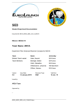
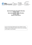
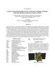
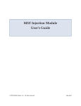
Code 242 Peltier Rack
User's Guide
LT2541/©2000 Gilson, Inc. All rights reserved
June 2000
Table of Contents
Declaration of Conformity
1 Introduction
Unpacking ............................................................................. 1-2
Customer Service .................................................................. 1-3
Technical Specifications ...................................................... 1-4
2 Installation
Rack Setup ............................................................................. 2-2
Placement on the Liquid Handler ............................... 2-2
Removing the Cover...................................................... 2-2
Electrical Connections ......................................................... 2-3
Rear Panel (Code 242 Peltier Rack) ............................. 2-3
Junction Box .................................................................... 2-3
Rear Panel (215 Peltier Controller) .............................. 2-4
Input Port ........................................................................ 2-5
Power Cord Connection ............................................... 2-7
3 Operation
Front Panel ............................................................................ 3-2
Operating Instructions ........................................................ 3-3
Using UniPoint™ with the Code 242 Peltier Rack ... 3-4
Using a Thermocouple with
the Code 242 Peltier Rack ............................................. 3-7
4 Maintenance
5 Troubleshooting
Electrical ................................................................................ 5-2
Input Contact Functions Not Operating .................... 5-2
Unit Not Operational .................................................... 5-2
Repair and Return Policies ................................................. 5-3
Before Calling Us ........................................................... 5-3
Warranty Repair ............................................................ 5-3
Non-Warranty Repair ................................................... 5-3
Rebuilt Exchange ........................................................... 5-3
Return Procedure ........................................................... 5-4
Appendix A
Replacement Parts and Accessories
Declaration of Conformity
Application of Council Directives:
89/336/EEC, 73/23/EEC
Standards to which Conformity is Declared:
EN55011, EN50082-1, EN61010-1 (IEC1010-1)
Manufacturer’s Name ........................................... Gilson, Inc.
Manufacturer’s Address ....................................... 3000 W. Beltline Highway
Middleton, WI 53562
EC Office Address .................................................. Gilson S.A.
19 Avenue des Entrepreneurs, B.P. 45
95400 Villiers-le-Bel, France
Type of Equipment ................................................. Laboratory Equipment
Model. ....................................................................... Code 242 Peltier Rack
Beginning with Serial Number: 259B9F001
Month and Year of Manufacture: February 1999
I, the undersigned, hereby declare that the equipment
specified above conforms to the above Directives and Standards.
Place: Middleton, WI (USA)
Issue Date: March 1999
Michael Jacquart
Senior Vice President
Corporate Technology Development
Introduction
1
The Code 242 Peltier Rack connected to the 215 Peltier Controller through a junction box,
uses thermoelectric heat pumps to provide heating and cooling of samples in 96-well, flatbottom, shallow microplates. Up to five Code 242 Peltier Racks can be placed on any Gilson
NEBULA SeriesT liquid handler. Power for all five racks is supplied by one 215 Peltier
Controller (ordered separately, reference 2515331). This configuration enables heating and
cooling of up to 960 samples.
Gilson Micro 215 Liquid Handler with five Code 242 Peltier Racks
1-1
1
Unpacking
Introduction
Unpacking
After unpacking, ensure you have the following:
•
•
•
Code 242 Peltier Rack (reference 25146331) with
cover, thermocouple insert, and 2-conductor
cable
215 Peltier Controller (ordered separately,
reference 2515331) with AC power cord
Junction Box (ordered separately, reference
2505332)
Inspect the items and promptly report any damage
to the carrier. Some carriers must receive concealed
damage claims within seven days of delivery.
Keep the original container(s) and packing material
in case the items must be returned to the factory.
Junction box (reference 2505332)
and 215 Peltier Controller (reference 2515331)
1-2
Introduction
Gilson, Inc. and its worldwide network of authorized representatives provide you with the following types of assistance: sales, technical, applications,
and instrument repair.
If you need assistance and are in the United States
please contact your regional Gilson representative
or call the Gilson Customer Service Department at
800-445-7661 or 608-836-1551. To help us serve you
more efficiently, please refer to the Before Calling
Us information on page 5-2.
Customer Service
Customer Service
1
You can also contact the Gilson Customer Service
Department via its electronic mail (e-mail) address:
[email protected]. Outside the United States,
contact your Gilson representative for assistance.
1-3
1
Technical Specifications
Introduction
Technical Specifications
Please be aware of the following before operating
the Code 242 Peltier Rack and the 215 Peltier Controller.
Note: Changes or modifications to these devices not
expressly approved by Gilson could void your
factory-authorized warranty.
These devices have been tested and found to comply
with the limits for a Class A digital device, pursuant
to Part 15 of the FCC commercial environment.
These devices generate, use, and can radiate radio
frequency energy and, if not installed and used in
accordance with the instructions, may cause harmful
interference to radio communications. Operation of
these device(s) in a residential area is likely to cause
harmful interference, in which case you will be
required to correct the interference at your own
expense.
Shielded cables must be used with these units to
ensure compliance with the Class A FCC limits.
1-4
Introduction
1
1-5
Introduction
1-6
1
Installation
2
This section will guide you through installing the Code 242 Peltier Rack on a NEBULA
Series liquid handler. It will also illustrate the necessary electrical connection to the 215
Peltier Controller through the junction box. Optional contact closure connections are also
described in this section.
2-1
2
Rack Setup
Installation
Rack Setup
Placement on the Liquid Handler
To install the Code 242 Peltier Rack, align the holes
on the bottom of the rack with pins on the liquid
handler’s 5-position locator plate. Then lower the
rack into place.
Removing the Cover
Your Code 242 Peltier Rack comes with the cover
installed. You will need to remove the cover before
placing the microplates in the rack.
To remove the cover:
2-2
1
Loosen the four thumb screws located on the
rack.
2
Lift the cover off the rack.
3
Place the microplates in the rack.
4
Replace the cover and tighten the four thumbscrews to enable efficient heating and cooling of
samples.
Installation
Rear Panel (Code 242 Peltier Rack)
Connect the power cable attached to the back of the
Code 242 Peltier Rack to a corresponding connector
on the junction box by first pulling the locking ring
slightly away from the cable and then tightening it
clockwise 1/4 turn.
Electrical Connections
Electrical Connections
2
Junction Box
Connect up to five Code 242 Peltier Racks to the
junction box. Keep the caps closed when not in use
to help prevent moisture damage.
2-3
2
Electrical Connections
Installation
2-4
Rear Panel (215 Peltier Controller)
Connect the quick-lock, 10-pin connector from the
back of the 215 Peltier Controller to its corresponding connector on the junction box.
Installation
Use the Code 242 Peltier Rack’s REMOTE port to
receive contact closure input from other devices.
The Code 242 Peltier Rack has one contact closure
input. An input contact is connected if it has a short
across the input or is held low (closed) by a TTL
output or other device. Never connect voltages
higher than 5V DC to an input. When using TTL
signals, be sure to match GROUND (
) connections. The GROUND wire on the 2-conductor cable
is the unsheathed wire.
Electrical Connections
Input Port
2
Closing the connection for the input contact will put
the rack(s) into a standby state. The STANDBY
indicator light will illuminate as will the indicator
light for HOT or COLD to indicate the previous state
which will resume if the contact is opened again.
Making connections
Before making contact connections, ensure that
power is turned off to the 215 Peltier Controller and
any peripheral devices.
To make the contact connection, you will need the
following:
•
•
2-conductor cable (reference 708022421)
small flat-blade screwdriver
2-5
2
Electrical Connections
Installation
To prepare and make connections with the 2-conductor cable:
1
Locate the terminal block connector for the
contact output device (such as a 506C System
Interface Module.)
2
Insert each wire into the appropriate slot on the
connector. Push the wire all the way in; then
tighten its corresponding pin screw.
Note: If you are using five Code 242 Peltier
Racks, you have the option of controlling all
racks through one pair of contacts or controlling
each rack individually using five pairs of contacts.
2-6
3
Connect the terminal block connector to the
output port on the contact output device (such as
a 506C System Interface Module.) Push the
terminal connector in as far as it will go. It is
designed to fit snugly into its receptacle.
4
Insert the plug at the other end of the 2-conductor cable into the port labeled REMOTE on the
rear panel of the Code 242 Peltier Rack.
Installation
Make sure the power to the 215 Peltier Controller is
swiched to off.
Locate the appropriate power cord for your line
voltage. Discard the other power cord.
Use the power cord to connect the 215 Peltier Controller from the power receptacle to an AC power
source.
Electrical Connections
Power Cord Connection
2
2-7
Operation
3
3-1
3
Front Panel
Operation
3-2
Front Panel
The front panel of each rack has a set of control
switches; a 3-position switch with corresponding
indicator lights (HOT-yellow, STANDBY-green,
COLD-blue) and a temperature control knob.
Operation
To operate the Code 242 Peltier Rack:
1
Turn on the power switch, located on the rear
panel of the 215 Peltier Controller.
2
Choose HOT, STANDBY (middle position), or
COLD using the 3-position switch on the front of
each Code 242 Peltier Rack.
Operating Instructions
Operating Instructions
3
Note: Place the rack in STANDBY for at least
two minutes before switching from HOT to
COLD or COLD to HOT.
3
Adjust the setting of the temperature control
knob on the front of each Code 242 Peltier Rack
to maximize or minimize heating or cooling.
Turn the knob as far as it will go in the clockwise
direction for maximum heating or cooling. Turn
the knob counterclockwise as far as it will go for
minimum heating or cooling.
3-3
3
Operating Instructions
Operation
3-4
Using UniPoint™ with the Code 242
Peltier Rack
The following instructions explain how to use
UniPoint to send contact signals to the Code 242
Peltier Rack. For more information, refer to the
UniPoint User’s Guide.
1
Open a Control Method.
2
In the Device menu, select Contacts.
Operation
Select the contact output in the Devices dialog
box that corresponds with the output contact on
the 506C System Interface Module that is connected to the REMOTE port on the Code 242
Peltier Rack(s). Enter a description for that
device (242 Peltier Rack(s), for example.) For
more information on making contact connections, refer to Section 2, Installation.
4
Click OK to add the description to the device.
Click OK again to exit the Contact dialog box.
5
In the Event menu, select Contact.
Operating Instructions
3
3
3-5
3
Operating Instructions
Operation
6
Highlight the device description that you created
in step 3. Enter the time for the event (either
contact open or contact close) to occur.
In the Action dialog box, choose open or close to
activate the contact at the time specified. Opening the contact initiates Peltier heating or cooling
depending on the setting of the 3-position rocker
switch on the rack. Closing the contact puts the
unit in a standby mode.
3-6
7
Click on Insert to add the event to the open
control method. Click on Done to return to the
Control Method screen.
8
Before running the method, ensure that all
electrical connections have been made and the
power switch on the 215 Peltier Controller is
switched to the on position.
Operation
The thermocouple insert (standard accessory) comes
installed in the front left corner of the rack and is for
use with a thermocouple wire (ordered separately,
contact Gilson Customer Service Department for
details). The use of a straight glass thermometer is
not recommended because it will interfere with Zarm travel.
Operating Instructions
Using a Thermocouple with
the Code 242 Peltier Rack
3
Remove the rack cover and insert the thermocouple
wire in the thermocouple insert until about 3 mm of
the thermocouple wire extends past the end of the
thermocouple insert under the cover. Bend the
thermocouple so that it fits flat against the bottom of
the insert. Replace the rack cover making sure not to
pull the thermocouple out of the insert. Make sure
the thermocouple wire is routed out of the path of
the Z-arm.
Equilibration of the samples and
rack takes approximately 30
minutes. After equilibration, the
temperature of the samples, if
using flat-bottom microplates as
recommended, will be within two
degrees Centigrade of the temperature indicated by the thermometer (ordered separately)
attached to the thermocouple wire
.
If the thermocouple wire is larger
than the hole in the insert, you can remove the
insert. Use a small flat-blade screwdriver to loosen
the set screw located on the left side of the rack
cover by turning it two complete revolutions counterclockwise. Remove the thermocouple insert and
place the thermocouple wire in the hole, making
sure adequate contact with the aluminum heat
transfer plate is established. Adequate contact is
established if the indicated temperature remains the
same when you push down on the thermocouple.
3-7
Maintenance
4
The Code 242 Peltier Rack and the 215 Peltier Controller are designed to require a minimum
level of maintenance. Keep the units clean for peak performance. Always turn the power
off to the 215 Peltier Controller and disconnect the rack(s) from the junction box before
cleaning the controller or the racks. Wipe all units with a soft cloth dampened with a mild
detergent and disinfect as needed.
4-1
Troubleshooting
5
5-1
5
Electrical
Troubleshooting
Electrical
Input Contact Functions Not
Operating
•
Make sure connections into the terminal block
connector contact output device (such as a 506C
System Interface Module) are secure
•
Make sure connections are secure in the ports
•
Check polarity of input to the Code 242 Peltier
Rack. Inputs should be a contact closure. If not,
it must be TTL level (logic O activates.) When
using TTL signals be sure to match ground
connections.
•
Check connections for proper pin assignments in
the contact output device
Unit Not Operational
5-2
•
Make sure the power switch on the back of the
215 Peltier Controller is on
•
Check AC power cord connections
•
Try a different AC outlet
•
Check all rack, junction box, and Peltier controller connections
Troubleshooting
Before Calling Us
Gilson Customer Service personnel will be able to
serve you more efficiently if you prepare the following information:
•
•
•
•
•
•
the serial number located on the back of the unit
the installation procedure you used
list of symptoms
list of operating procedures and conditions you
were using when the problem arose
list of other devices connected and a description
of those connections
list of other electrical connections in the room
Repair and Return Policies
Repair and Return Policies
5
Warranty Repair
Units covered under warranty will be repaired and
returned to you at no charge. If you have any
questions about applicability, please contact the
Gilson Customer Service Department or your authorized representative.
Non-Warranty Repair
Contact your local Gilson representative or the
Gilson Customer Service Department to discuss
service options and make arrangements to return
the instrument, if necessary.
Rebuilt Exchange
For some units, rebuilt exchange components are
available. Contact the Gilson Customer Service
Department for details.
5-3
5
Repair and Return Policies
Troubleshooting
Return Procedure
In the United States, contact the Gilson Customer
Service Department to obtain a Return Goods Authorization (RGA) number before returning any
Gilson equipment.
To return a piece of equipment:
•
Carefully pack the unit to prevent damage in
transit. Check with Gilson regarding proper
method of shipment. No responsibility is assumed by Gilson for damage caused by improperly packaged instruments. Indicate the RGA
number on the carton and on the packing slip
•
Always insure for the replacement value of the
unit
•
Include a description of symptoms, your name,
address, phone number and purchase order to
cover repair costs, return and shipping charges,
if your institution requires it.
Ship to:
Gilson, Inc.
Attention: Customer Service
RGA: (indicate your RGA number here)
3000 W. Beltline Highway
Middleton, WI 53562-0027
5-4
Replacement Parts and Accessories
A
Reference Number
Description
25146331
Code 242 Peltier Rack for 96-well shallow microplates
includes cover, thermocouple insert, and 2-conductor cable
2515331
215 Peltier Controller includes AC power cord
2505332
Junction box for use with the Code 242 Peltier Rack and 215
Peltier Controller
708022421
2-conductor cable for making contact connections, standard
accessory with the Code 242 Peltier Rack
250463323
Thermocouple insert, standard accessory with the Code 242
Peltier Rack
A-1