1
VEREX Director
User's Guide
V4.73
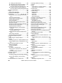
Contents
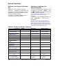
Using this Guide ..................................................................................................................................... v
Welcome ..................................................................................................................................................... 1
Entering an Area & Disarming the System ............................................................................................. 2
Welcome to VEREX Director .................................................................................................................. 4
Start-up and Logging In ............................................................................................................... 4
Exiting, Logging Off, or Changing Operators ............................................................................... 6
The Desktop ................................................................................................................................ 8
Other Desktop Choices.............................................................................................................. 10
Running Reports, and Monitoring System Activity .............................................................................. 13
Time-and-Attendance Reporting........................................................................................................... 14
Required-Attendance Time-Periods........................................................................................... 18
Roll-Call Reports (v4.61) ...................................................................................................................... 20
Reporting on System & Personnel Activity ........................................................................................... 21
Reporting on Previous Guard-Tours ..................................................................................................... 24
Reporting on User Access Authorities (by Area, Door, or Floor) .......................................................... 26
Reporting on Users, System/Device Settings, etc. ............................................................................... 28
Reporting on Operator Audits or Panel Communications Logs ............................................................ 30
Reporting on Panel Diagnostics (≥V4.4)............................................................................................... 32
Working with the Report Viewer ........................................................................................................... 34
Monitoring System Activity.................................................................................................................... 35
Alarm and Activity Monitoring .................................................................................................... 35
'Activating' and Using the Monitoring Window............................................................................ 36
Limiting the Window to Show Only Specific Messages (Sorting and Filtering) .......................... 38
Acknowledging Alarms (Comment / Resolve)............................................................................ 40
When Messages Cannot be Transmitted to the VEREX Director Software ............................... 41
Working with Video Events (≥V4.5)............................................................................................ 42
Visually Verifying Users (Photo-Verification) ........................................................................................ 44
Guard-Tours: Monitoring...................................................................................................................... 47
Guard Tours: Initial Set Up ....................................................................................................... 50
Checking Status and Controlling Items ................................................................................................. 53
Maps and Video (Visual Monitoring & Status/Control) .......................................................................... 54
Status and Control Using Visual Director................................................................................... 54
Camera Status/Control and Adjustments................................................................................... 62
Controlling a Pan/Tilt/Zoom Camera ............................................................................. 63
Adjusting Camera Quality for your Connection/Bandwidth ............................................ 66
Initial Set Up of: Views, Maps, Cameras................................................................................... 68
Checking Status & Controlling Items .................................................................................................... 76
Introduction to Status & Control ................................................................................................. 76
Using the Status Toolbar ........................................................................................................... 78
Miscellaneous Status Tasks ...................................................................................................... 80
Panel Date and Time..................................................................................................... 80
Resetting Users' Antipassback Status........................................................................... 82
Clearing a "Bad Card/PIN Global Lockout".................................................................... 84
Checking System Status (Remote Diagnostics) ............................................................ 86
Checking the Status of Panels (Equipment) .............................................................................. 88
Checking Power Levels (≥V4.4)................................................................................................. 90
Checking the Status of Modules ................................................................................................ 92
Checking Status or Controlling a Suite Security System............................................................ 94
21-0381E v4.7.3 (2008.08)
© 2008 CSG Security Inc. / Sécurité CSG Inc.
i
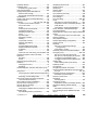
Checking Status or Controlling Items by Area ........................................................................... 96
Area Users (Activity, User Count, and APB-Reset) ....................................................... 99
Checking User In/Out Status ................................................................................................... 102
Checking Status or Controlling Individual Doors...................................................................... 104
Checking Status or Controlling Elevators ................................................................................ 106
Checking Status or Controlling Floors ..................................................................................... 108
Checking Status or Bypassing Input Points (Sensors)............................................................. 110
Checking Status or Controlling Outputs (Electronically switched Devices) ............................. 112
Panel Communications and Updates ................................................................................................. 114
Panel Communications ............................................................................................................ 114
Activating Communications and Transferring Panel Settings .................................................. 116
Viewing the Status of Previous Communications Sessions ..................................................... 120
Correcting Communication/Update Errors ............................................................................... 122
Checking Account Status (≥V4.4)....................................................................................................... 124
Panel Firmware Files, and Updating Panel Firmware (≥V4.4) ............................................................ 125
Activating Panel Firmware Files............................................................................................... 125
Updating Panel Firmware ........................................................................................................ 126
Administration and Maintenance ......................................................................................................... 129
Operators (People Who Can Use This Software) ............................................................................... 130
Setting or Changing an Operator's Password.......................................................................... 132
Operator Settings (v4.6) .......................................................................................................... 134
Operator Permissions .............................................................................................................. 136
Scheduled Event Filtering for Operators .................................................................................. 138
Schedules for User-Access and Area Automation.............................................................................. 140
Holidays and Time-Change Dates...................................................................................................... 144
Authority Groups to Manage Large Numbers of Authorities (v4.6) .................................................... 146
Authorities for Users/Entrants (≥V4.4) ................................................................................................ 148
Custom Information Categories for Users (Custom User Information) ............................................... 154
Users (Entrants / Panel Users) ........................................................................................................... 156
The Photo-Badging Option ...................................................................................................... 162
Cards that Have Been Lost...................................................................................................... 166
Fall-Back Users (Can Enter During Comms Failure) ............................................................... 168
System Maintenance Tasks ............................................................................................................... 170
Password and Personal ID Number (PIN) Issues .................................................................... 170
Large Systems--Checking for Software vs. Panel Differences / Conflicts ................................ 172
Client/Server Systems: Checking to See Who Else is Logged onto the Database ................ 173
Checking / Repairing the VEREX Director Database Tables ................................................... 174
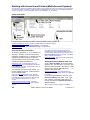
Backing up or Restoring the Database .................................................................................... 176
Making a Database 'Backup' Using the Director Software .......................................... 177
Making a Database 'Backup' Using the Table Repair Utility........................................ 178
Setting Backups to Occur Automatically (Scheduled Backups) v4.5 ........................... 179
Reverting to (Restoring) a Backup Copy of the VEREX Director Database ................ 180
Exporting or Importing Activity or Audit Logs (Archive) ............................................................ 182
Removing old Activity or Audit Logs (Purge)............................................................................ 184
Operating System Maintenance............................................................................................... 185
ii
VEREX Director V4.73 User's Guide
21-0381E v4.7.3
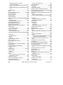
System Configuration............................................................................................................................ 187
Working with Accounts and Folders (Multi-Account Systems)............................................................ 188
Visual Quick-Start .................................................................................................................... 188
After a Multi-Server Login ........................................................................................................ 191
Advanced Sorting..................................................................................................................... 192
Users and Holidays Shared Across Multiple Accounts ....................................................................... 193
Introduction .............................................................................................................................. 193
Phase 1: Account-Specific Data.............................................................................................. 194
Phase 2: Community Groups .................................................................................................. 196
Phase 3: Shared Users and Holidays ..................................................................................... 200
Phase 4: Assign Shared Items to Accounts ............................................................................ 202
Account-Wide Panel Settings (Feature-Set, Service PIN, etc.) .......................................................... 204
Event Responses for Acknowledging Alarms ..................................................................................... 208
Alarm / Event Instructions................................................................................................................... 210
Enabling Sounds (to be associated with event/alarm messages)....................................................... 212
Customizing How Events are Displayed (Event Priority) .................................................................... 214
Detailed Operator and User Audit Trail (≥V4.6) .................................................................................. 216
Setting up Video Events (≥V4.5)......................................................................................................... 217
Software-Based Text Paging (Serial Reporting) ≥v4.4 ....................................................................... 218
Panels, Panel Groups, and Connection Settings .............................................................................. 220
Panel Groups and Connection Settings ................................................................................... 220
System Panels and Displayed Item-Numbers.......................................................................... 222
System Settings for each Panel (≥V4.4) ............................................................................................. 224
General System Settings for a Panel ....................................................................................... 224
Intrusion Settings for a Panel (≥V4.4) ...................................................................................... 226
Monitoring, Numeric Paging, & Remote Mgt. Settings ............................................................. 228
System Card-Access Settings ................................................................................................. 232
Equipment Settings (Pseudo / Internal Inputs) ................................................................................... 234
Areas and Related Settings. ............................................................................................................... 236
Activity Monitoring and Auto-Arming ........................................................................................ 242
Area Groups (≥V4.4) and Multi-panel Arm/Disarm (≥V4.5)................................................................ 244
Setting up Multi-Panel Arm/Disarm (≥V4.5) ............................................................................. 245
Expansion Modules ............................................................................................................. .............. 246
Suite-Security Keypads and Related Settings .................................................................................... 250
Doors, Readers, and Related Settings ............................................................................................... 254
Defining a ‘Required Attendance’ Zone ................................................................................... 257
About Video Events ................................................................................................................. 261
Elevators (Lifts) and Associated Readers........................................................................................... 262
Floors (Pertaining to Access-Controlled Elevators / Lifts)................................................................... 268
Input Points—Monitored Sensors ....................................................................................................... 270
Input Points—Pre-Defined Sensor Types ................................................................................ 274
Input Points—Custom Point Types .......................................................................................... 275
Custom Circuit-Types for Input Points (≥V4.4)......................................................................... 278
Programmable Outputs (Signalling & Device-Switching) .................................................................... 280
The Numeric Paging Feature ...................................................................................... 280
Event Types and Events:............................................................................................. 282
Commands (when you right-click an item):.................................................................. 283
Cadence (Getting the Output to Pulse On and Off) (≥V4.2): ....................................... 283
Multi-Condition Equations:........................................................................................... 283
Programmable Output Functions ........................................................................................................ 285
21-0381E v4.7.3 (2008.08)
© 2008 CSG Security Inc. / Sécurité CSG Inc.
iii
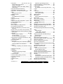
Installation and Technical Reference................................................................................................... 291
PC Issues and Software Installation ................................................................................................... 292
Recommended Computer Specifications................................................................................. 292
Serial Port Installation and Set Up ........................................................................................... 294
Windows Settings Required..................................................................................................... 295
Software Installation for a Fresh/New System ......................................................................... 297
Upgrading from an Earlier Version of Software........................................................................ 298
If You Need to Transfer the Database to a Different PC ............................................. 300
DCOM Setup ........................................................................................................................... 302
Firewall Settings (e.g., Windows XPsp2) ................................................................................. 302
Software Activation and Licensing...................................................................................................... 303
Software "Activation Key" ........................................................................................................ 303
Activating Your Software ......................................................................................................... 303
Upgrading Your Software (Adding Optional Features)............................................................. 305
March Networks R4-R5 DVR Support ................................................................................................ 306
Network USB HASP Key (Director ≥V4.51)........................................................................................ 306
Remote Software Download and Remote Access (≥V4.7) ................................................................. 308
Client/Server Issues and the Director Server Manager (v4.7) ............................................................ 309
Client/Server Access and Permissions............................................................................................... 311
Server Validation Certificates (≥V4.72) .................................................................................... 311
Client Access (Allowable Client List)........................................................................................ 312
Setting Up Client Permissions ................................................................................................. 316
New Installation? Try the Wizard ! ..................................................................................................... 318
Panel Connection Overview ............................................................................................................... 319
IP Connectivity......................................................................................................................... 321
Secure IP Communications (≥V4.72)....................................................................................... 321
PC-to-Panel—Direct Connection ............................................................................................. 322
PC and Panels—Modem Connections .................................................................................... 324
PC Modem Installation or Connection ......................................................................... 324
Windows Modem Setup .............................................................................................. 324
Panel Modem .............................................................................................................. 325
Serial Port / Modem Setup (Communications Manager) .................................................................... 326
Communication Pools for System Panels........................................................................................... 330
Setting Up a New System (Commissioning)....................................................................................... 332
Importing Settings from an Existing VEREX Director System Panel....................................... 336
Customizing the MyTools Bar............................................................................................................. 338
System Capacities.............................................................................................................................. 340
Advanced Database Features ............................................................................................................ 345
Overview of Features............................................................................................................... 345
SQL Server Support ................................................................................................................ 345
User-Logins (Needed for: Database Query, and SQL Server Support) .................................. 346
Linking to the Database (Used for: Custom Query/Reporting; ERM Integration) ................... 348
Automated User-Import (Used for: ERM Integration).............................................................. 352
Manually Importing User-Data From a Text File ...................................................................... 354
System / Hardware Reference ........................................................................................................... 355
Keypad Tone Reference (≥V4.5 with ≥V4.42 firmware)...................................................................... 358
On-Line Support & Product Information.............................................................................................. 360
Index ....................................................................................................................................................... 361
iv
VEREX Director V4.73 User's Guide
21-0381E v4.7.3
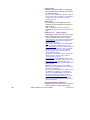
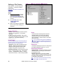
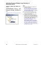
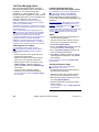
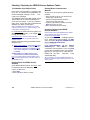
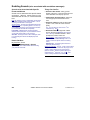
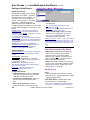
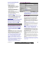
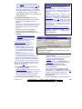
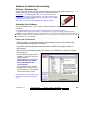
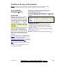
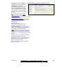
Using this Guide
Each topic th at pertains to a specif ic VEREX
Director screen generally sho ws ho w t o do
things on th e left, and w hat t he av ailable
settings mean on the right. This may pe rtain
to a sing le pa ge, or sets of 'facing pages ' as
required for larger topics. A b old double-line
marks the en d of each 'Ho w-To' section, and
the 'selection -descriptions' for the present
screen follow thereafter.
Use the table of contents (at the front), or the
index (at the back) to find a desired topic. The
table of contents sho ws the topics as they
appear in ea ch chapter, while the index lists
topic keywords alphabetically.
Tip: The bottom of each right-hand page shows you
which chapter you are presently 'in'. (These match the
topic-buttons across the top of the on-line help.)
To find specific information within a topic, skim
through the s ubheadings ( on the left), o r the
selection-descriptions for th e specific scr een
(on the right) to find what you're looking for.
Tip: Additional notes, and links to other applicable
sections are provided throughout. You can typically
avoid reading the note text unless you run into
problems or otherwise feel that you need more
information.
On-Line Help Tip: The on-line help is structured in the
same basic format as this User's Guide, with topic
buttons that match the chapters and navigation footers
in this guide. As you refer to the User's Guide, you are
already becoming familiar with the on-line help (and
vice-versa).
Copyrights and Trademarks
™ VEREX Director, G-Prox, and Netvision are
trademarks of CSG Security Inc. / Sécurité CSG
Inc.
™ Pentium is a trademark of Intel Corporation
® Microsoft, Windows, Windows 2000, and
Windows XP, are trademarks or registered
trademarks of the Microsoft Corporation.
© Copyright 2008
CSG Security Inc. / Sécurité CSG Inc.
All rights reserved.
Disclaimer
All soft ware, firmw are, draw ings, diagrams,
specifications, catalogues, literature, manuals
and other supplied materials shall con stitute
the proprietary information of the
manufacturer. In the interests of ongoing
improvement in quality and design, we reserve
the right to change pro duct specific ations
without prior notification.
Attention: Physical a lteration of hardw are
components or removal of electrical de vices
may void warranties, and/or affect radiofrequency and electromagnetic emissions.
This document is not to be copied, decompiled, or re-distributed in any form without
prior written consent.
© Copyright 2008
CSG Security Inc. / Sécurité CSG Inc.
21-0381E v4.7.3 (2008.08)
© 2008 CSG Security Inc. / Sécurité CSG Inc.
v
vi
VEREX Director V4.73 User's Guide
21-0381E v4.7.3
Welcome
21-0381E v4.7.3
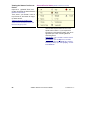
Welcome
Report Control
Admin
Sys Config
Tech-Ref
1
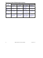
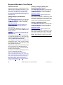
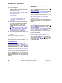
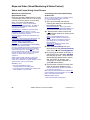
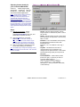
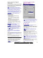
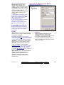
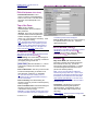
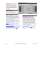
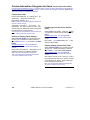
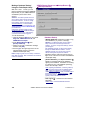
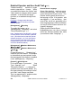
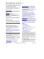
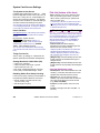
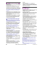
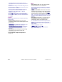
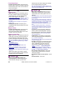
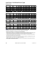
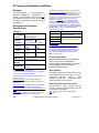
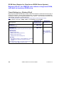
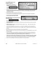
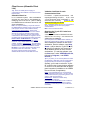
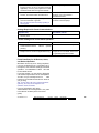
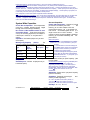
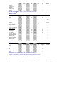
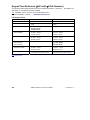
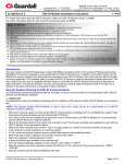
Entering an Area & Disarming the System
Re
Area
Setting
Disarmed (Off)
ader/Door Mode
Locked &
Card Only
Locked &
Card+PIN
Present card,
open the door
Present card, enter PIN
open the door
Armed & 'Auto
Disarm on Valid
Token'
Armed & 'PINOnly' or 'ID+PIN'
Present card,
open the door
Present card, enter PIN
open the door
Present card, open the
door. Then log into
panel and disarm it.
Present card, enter PIN
open door. Then log
into the panel & disarm
it.
Armed &
Dual Custody
Present card, open the
door. Then login with
two user PINs (or
ID+PIN), & disarm
area.
Present card, enter PIN
open door. Then login
with two user PINs (or
ID+PIN), & disarm
area.
2
Locked &
Card or UID/PIN
Present card or enter
user no., enter PIN
open the door
Present card or enter
user no., enter PIN
open the door
Present card or enter
user no., enter PIN
open door. Then log
into the panel & disarm
it.
Present card or enter
user no., enter PIN
open door. Then login
with two user PINs (or
ID+PIN), & disarm
area.
VEREX Director V4.73 User's Guide
Locked &
UID/PIN Only
Enter UID+PIN (or PIN
only), open the door
Enter UID+PIN (or PIN
only), open the door
Enter UID+PIN (or PIN
only), open the door.
Then log into panel and
disarm it.
Enter UID+PIN (or PIN
only), open the door.
Then login with two
user PINs (or ID+PIN),
& disarm area.
21-0381E v4.7.3
If the door is unlocked, access is not controlled (simply
open the door to enter the area). Conversely, if the
door is locked, and all cards are presently 'locked out',
users will be unable to enter.
Card Number: As an alternative to the user ID number
(UID), and/or access cards, the system can be set for
entry and login using the card number instead (4-10
digits).
Visitors that must be Escorted: Persons with a card set
as "Visitor (Escort-Required)" must be escorted at each
controlled reader (valid escort or regular cardholder-depending on the system settings).
To enter at a controlled door and disarm the area, an
entry delay must be in effect. As well, only the users
with authority to both enter the door at this time AND
disarm the area will be granted entry.
The 'ID + PIN' or 'PIN Only' login requirement is
determined by the 'Feature-Set' selection for the
account.
Dual Custody (and Escort mode) is supported at
individual readers as well.
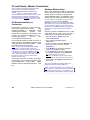
Using an Arming Station: Additional features
and entry options are provided through an
arming station. These unit s are essentially a
proximity rea der w ith keyp ad, plus addit ional
status indicat ors and features. For details on
using an arming station, please refer to th e xL
(panel/keypad) User's Guide.
Readers set to Enable or Disable Cards:
Some readers may be set to enable or d isable
specific types of cards (su ch as visitor cards,
or all temporary cards, etc.)--w ith or without an
associated door being unlo cked at this time.
All other (valid) cards will be granted access as
usual.
To Enter using a Do or-Opener Button: Use
your access card and/or PIN to unlock the door
(and activate the button). Then, simply press
and release t he door-opener button.
Once
inside the area, 'log' in at a n LCD keypad, and
disarm the ar ea if required (i.e., if NOT set for
"Auto-Disarm on Valid Token").
If Y ou ar e Being For ced to E nter: With
Card+PIN mo de in effect, you can trigger a
'Duress' alarm by reversing the last 2-digit s of
your personal ID number (P IN). This can also
be done when 'logging' into an LCD keypad.
To Exit Using an RTE (REX) Button: Simply
press and b riefly hold t he request-to-ex it
button.
If you Hold the Door Open: If the door is
held open for 'too long', a 'Door Held Open'
message will be logged.
A person holding a door open, or indicating that they
are being forced to enter may also trigger an alarm
(depending on the monitoring settings for the specific
door).
Entering Dur ing the P re-Arming Cy cle:
With a sched uled arming, authorized persons
entering during the 15 minut e pre-arming cycle
will be grante d access--without interrupting the
arming cycle. They would then have to:
+ Extend the closing time ("work-late"), or
+ Manually disarm the area once the final prearm countdown begins, or;
+ Leave before the arming occurs.
Note: Cards can either be disabled permanently, or
allowed to be re-enabled later.
21-0381E v4.7.3
Welcome
Report Control
Admin
Sys Config
Tech-Ref
3
Welcome to VEREX Director
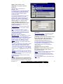
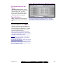
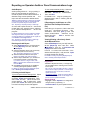
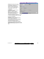
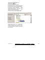
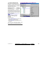
Start-up and Logging In
Multiple Instances: Beginning with Director v4.70, you
can run multiple copies of the interface (…Director.exe).
This allows you to access different features and/or
different accounts at the same time.
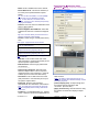
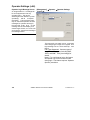
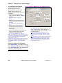
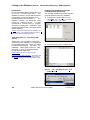
Starting the VEREX Director Software
Select Start, Programs, VEREX Di rector V4 ,
and VEREX Director, and wait for the start-up
screen to appear.
Activation Key: The VEREX Director software uses a
small 'activation key' to manage software licensing and
optional features. This device must be plugged onto
the PC that contains the software database (≥V4: USB
connector; ≤V3.3.2: Parallel/printer port; V3.3.3:
Either).
Note: Director software ≥V4 will not start up if the
USB key is missing.
Client/Server Systems: Take care to ensure that the
VEREX Director software is NOT already running
before attempting to start it. Troubleshooting Tip: If the
desktop is acting strangely, you may have two copies of
the software running (and you've run out of memory).
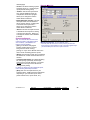
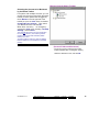
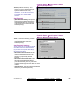
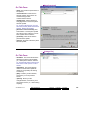
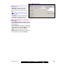
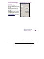
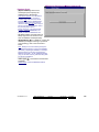
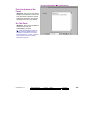
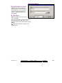
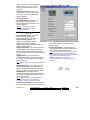
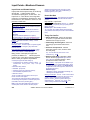
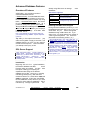
Logging In (Single-PC)
shut down the software (incl. the communications or
server module), then start the software and login again.
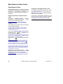
On-Line Help Language
For versions of VEREX Director that in clude
multi-language help file s, t he on-line help will
normally com e up in the la nguage assoc iated
with your op erator settings.
You can als o
select a different language-version if desired
(for this work-session).
Selecting a Different Help Language: Open the Help
menu, select Language, and then select from the
available choices.
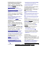
The Auto-Lockout Feature
If you do not use your keyb oard for a sp ecific
period of time , the soft ware will automatically
go into 'lockout' mode to
protect against an
unauthorized person view ing or changing
items. (For details, refer to the
[Lockout]
description).
To set the period of time before the keyboard lockout
will occur (when you are logged in), refer to the section
on "Operators".
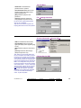
To gain access to your a ssigned items and
features, you must first
perform a 'Login':
Select Login from the toolb ar, and then enter
your name and pass word, pressing Tab in
between. Then, press Enter, or click Login.
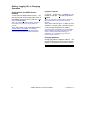
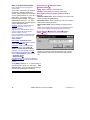
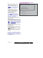
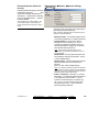
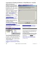
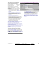
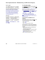
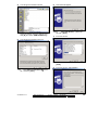
Logging In (Client/Server)
Select Login from the toolb ar, and then enter
your name and pass word, pressing Tab in
between. (En sure the "Serv er Location" is set
as well, if present.) Then, press Enter, or click
Login.
If a "Cannot Connect to Server" screen
appears, check that you hav e not mistyped the
"Server Location".
Note: The Director-server PC and software must be
running (this is the PC that includes "...DirectorServer.exe", and typically contains the database as
well. For additional things to check, refer to "Director
Server Manager and Client/Server Issues" (near the
back of this guide).
If you just upgraded for client/server (server location
missing on login screen): You may need to login once,
4
VEREX Director V4.73 User's Guide
21-0381E v4.7.3
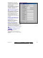
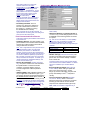
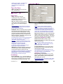
- Name: A valid operator's name.
- Password: The operator's assigned
password.
Default Operator Name & Password:
Operator, 1234
The default login name and password take effect
only until changed by a system administrator.
To protect against unauthorized access to the
software, the default password should be
changed right away.
If your login name and password are no longer
supported after upgrading from an earlier
software revision, refer to "Upgrading from an
Earlier Version of Software", paying special
attention to converting your previous database.
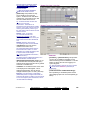
- Server Location: In a multi-PC (clientserver) installation, this allows you to
identify the VEREX Director server. Select
(or type in) the server "PC name" (or its
network "IP address").
Director-Server PC: This is the PC that includes
"...Director-Server.exe", and typically contains
the database as well.
Tip: This can be an IP address, or a name
(FQDN). Contact your IT rep. for assistance if
needed. For remote access (different PC) with
certificate authentication, this value must be as
supported by the certificate.
More: Server Validation Certificates
Multi-Server Login: You can select up to 6 servers
for simultaneous login. This allows listing and
selecting accounts from any of the server PCs without
having to log out in between. (All servers you are
logged into appear under [Server] in the 'tree'.)
Related: "Working with Accounts and Folders"
Tip: Use semicolons (;) to separate multiple server
names, or click [...].
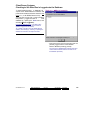
- [...]: Opens a small screen to allow selecting multiple
servers. (The login will apply to all server PCs
shown in this screen.) For each server, type or
select the PC name (or IP address) at the bottom of
the screen, and click [Add]. You can also [Delete]
a selected server, or [Replace] it after typing a new
name.
Attention: Your operator login name and password
must be valid for all of the desired servers. (You will
be logged into the servers for which your login name
and password are valid.)
To login at the server PC itself, use the PC name
(not the IP address).
------------------------- [Login]: If the entered name and password are
valid, the operator will be provided access to the
items and features as assigned in their operator
21-0381E v4.7.3
Welcome
Report Control
permissions.
Server Connection Status: A small screen will show
you the connection progress while a connection is
made with your selected server(s).
- [Lockout]: This shuts down the software except
for the status toolbar. (Tip: If the same
operator logs back in, the software will also
remember what account they were 'in'.)
The status toolbar requires that the software be
connected with the applicable panels. For details on
the status toolbar, or on establishing panel
communications, refer to "Checking Status and
Controlling Items".
- [Cancel]: Aborts the login request.
- [PROXY]: Provides settings used to connect
out to the Director-server via the internet
through a proxy server.
Settings: "Proxy Type" (select "None" if not using this
feature), "Domain", and a "User Name" and
"Password" that has suitable permissions on that
domain. (For these and other proxy settings, get an
'IT' person to help you.)
Note: Port 443 must be 'open' on the network for the
Director-server.
Admin
Sys Config
Tech-Ref
5
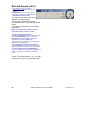
Exiting, Logging Off, or Changing
Operators
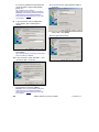
Shutting Down the VEREX Director
Software
To shut down the VEREX Director softw are,
click the X in the ex treme upper-right corner of
the VEREX Director screen (or open the File
menu, and select Exit).
Tip: If you changed any desktop settings, and would
like to retain them, be sure to click the check-box
provided.
Then, select "Yes" on the confirmation screen.
The RPC Server is Unavailable: This message
appears if the Director-Server application had been
shut down previously (before the Director software).
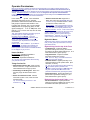
Logout or Lockout
To 'log' off, simply sele ct Logout on t he
toolbar (or open the
File menu, and select
Logout).
Tip: If you changed any desktop settings, and would
like to retain them, be sure to click the check-box
provided.
Then, select Yes to 'logout ', or No to pu t the
software in 'L ockout' mode. (See the 'Lo gout /
Lockout' screen descriptions for details.)
To protect against unauthorized access to the VEREX
Director software, it is always a good idea to use the
logout (or lockout) feature before leaving your
workstation. (For a related topic, see "The AutoLockout Feature", previous.)
Changing Operators
Changing ope rators is simply a matter of one
operator logging out, and th e second operator
logging in. (For details, see previous / above.)
6
VEREX Director V4.73 User's Guide
21-0381E v4.7.3
(When Exiting)
- [Yes]: Logs the present operator out,
and shuts down the VEREX Director
software.
- [No]: Aborts the exit request.
If you have changed any desktop settings, a
check-box will be provided to let you save
your settings.
Logout / Lockout
- [Yes] (Logout): Logs the present
operator out, shutting down access to
the VEREX Director software.
(Until the next valid operator performs
a 'login'.)
- [No] (Lockout): This shuts down the
desktop except for the status toolbar (and login
button). (Tip: If the same operator logs back in,
the software will also remember what account
they were 'in'.)
The status toolbar requires that the software be
connected with the applicable panels. For details on
using the status toolbar, or on establishing panel
communications, refer to "Checking Status and
Controlling Items"
- [Cancel]: Aborts the logout request, leaving the
present operator logged in.
If you have changed any desktop settings, a checkbox will be provided to let you save your settings.
(For a related topic, see "The Auto-Lockout Feature",
previous.)
21-0381E v4.7.3
Welcome
Report Control
Admin
Sys Config
Tech-Ref
7
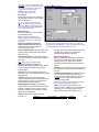
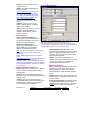
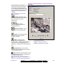
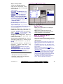
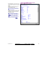
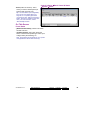
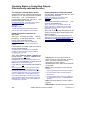
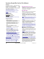
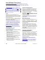
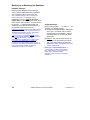
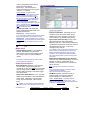
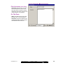
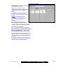
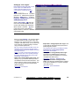
The Desktop
Your 'Window' to the System
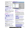
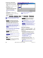
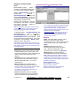
Navigating the Desktop
The desktop is your interface to the VEREX
Director software, providing a familiar Windows
'look and fee l', with ac cess to all features and
items assigne d to you as a VEREX Dir ector
operator.
The VEREX Director interface can be s et as
desired by each individua l operator. This
includes whether they prefe r the MyTools bar,
or the Tree window, plus the sizing o f the
desktop sections, and other settings.
Many screens are divided i nto 'tabs' of related
settings. (St art w ith the 'Standard' tab, and
look in any a dditional tabs that are of interest
to you.) Some screens
also includ e the
familiar windows ‘scroll-bars’ whenever an item
is too large to fit on-screen.
Selecting Desktop Items to be
Displayed
The [Tree], [MyTools] and [Events] buttons
on the toolbar allow viewing or hiding d ifferent
aspects of the desktop (try it!).
Your MyTools Bar: You can customize the look and
content of the MyTools bar to your own preferences.
For details, refer to "Customizing the MyTools Bar".
Account-Folders: For systems with single-account
licensing, only one account will appear in the tree. In
larger systems, [Account Folders] will be shown in the
tree for operators with multi-account permissions (or
that have the authority to edit account folders).
Saving Your Desktop Settings
After changin g an aspect of the deskto p (the
sizing, Forms/Grid mode, and/or which aspects
are to be displayed, you
can save
your
changes so t he desktop a ppears in the same
format the nex t t ime you lo gin. To save your
changes, op en the
View menu,
select
Desktop Settings, and then Save.
Tip: You will also be asked if you want to save your
changes whenever you logout or exit from the software.
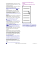
Changing the Size of the Desktop
To resize the entire desktop, click and drag the
bottom right corner to the d esired position. (If
the screen is presently 'max imized', you'll first
need to double-click the blue title-bar, or click
the middle button in the upper right corn er of
the screen.)
To ‘max imize’ the desktop, double-click the
blue title-bar, or click the middle button in the
upper right corner of the screen.
Changing Proportions of Desktop Areas
To change the proportion of the desktop, move
the mouse to the edge of a screen area (such
as between the 'tree' and forms/grid area), and
watch for the cursor to cha nge shape. Then,
click-and-drag the edge of the window to a
new location.
Tip: You can also
maximize the for m/grid
area, or the monitoring window (i.e., cause it to
fill the entire screen) by double-clicking the
title-bar for th e specific window twice. (Also
see "Resetting...", to follow.)
Changing the Position of Desktop Items
Each portio n of the
desktop can be
repositioned, and/or viewed on its own. This is
especially us eful on a
multi-monitor PC,
allowing an item such as the monitoring
window to be viewed separately.
To relocate an item, 'drag-and-drop' the item
by its title-bar , while watching for the gr eyed
box indicating the new position.
To view an item 'full-screen' (such as the monitoring
window), double-click its title-bar twice. To access the
main desktop screen again, double-click the title-bar
once again.
8
VEREX Director V4.73 User's Guide
21-0381E v4.7.3
Resetting the Desktop
After moving and resizing areas of
the screen, you may wish to reset the
desktop to e ither your last saved
settings, or to the initial factory default
layout.
Last Saved Settings: Click Reset on
the toolbar (o r open the View menu,
and select Desktop Setti ngs, and
Reset).
Factory-Default Layout : Open the
View menu, and sele ct Desktop
Settings, and Default).
Tip: If a window or portion of the desktop is
presently "maximized" (fills the entire
screen), you'll need to double-click its titlebar to access the menu or toolbar.
Note: If your desktop was accidentally
saved with the monitoring window
'undocked' and hidden behind the main desktop, follow
the preceding steps for "Factory Default Layout".
- The Menu: Provides access to some
miscellaneous features of the VEREX Director
software. Tip: The Tools menu provides
access to Wizards that simplify setting up a
new system, and/or enabling communications
with a panel.
- The Toolbar: Provides access to some
common tasks.
- The 'Tree' (optional): This is an expandable/
collapsible outline that allows selecting an
account, and provides access to most topics
including system configuration, management,
and status & control. Click [Tree] on the toolbar
to view or hide the 'tree'.
- The 'MyTools' Bar (optional): This is a
customizable list of tasks/items that can be
used as alternative to the 'tree'.
Tip: Click [MyTools] on the toolbar to view or hide the
MyTools list/bar. Note: Only the items allowed by
your operator permissions will be visible in the Tree
and MyTools Bar. As well, for items pertaining to a
specific account, you must first double-click to enter
the account.
Tip: You can customize the look and content of the
MyTools bar when you are logged in (View Ö MyTools
Ö Customize). For details, refer to "Customizing the
MyTools Bar".
21-0381E v4.7.3
Welcome
Report Control
MyTools Doesn't Work: If you select [ MyTools ],
and only a small empty 'button' appears, this means
no items are assigned to the 'MyTools' bar. See the
previous tip to fix this.
- The Forms/Grid Area: This area shows
details on your present topic (as selected from
the tree or MyTools bar). This can be set for
either a forms view (typical / data entry), or
'grid' format (experienced persons / viewing
and sorting lists).
(Use the Form / Grid button on the toolbar to switch
views.)
- The Monitoring Window (optional): This
area shows recent events that have been
received (for a selected account).
Click [Events] on the toolbar to view or hide the
monitoring window.
Multi-Account Systems: With multiple accounts, the
monitoring window shows the events for your present
account. (Select [Account Folders] in the tree, then
locate and double-click your desired account.)
To set the account to be monitored by the status
toolbar, click [Monitor] on the far-right end of the
toolbar.
- The Status Bar: This area (at the extreme
bottom of your desktop) shows whether or not
you are connected with a selected account
(i.e., associated panels), plus other
communications-related status messages.
Admin
Sys Config
Tech-Ref
9
Other Desktop Choices
Tip: You can save your desktop changes at any time:
Open the View menu, select Desktop Settings, &
Save. Note: You will also be asked if you want to save
your changes whenever you logout or exit from the
software.
Selecting Desktop Items to be
Displayed
The [Tree], [MyTools] and [Events] buttons
on the toolbar allow viewing or hiding d ifferent
aspects of the desktop (try it!).
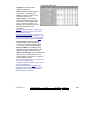
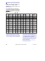
Listing Items Panel-by-Panel vs. in a
Single List and Showing or Hiding
Panel References in Forms
For some tasks, you hav e two choices a s to
how items will be displaye d (in a single list,
versus panel-by-panel), and/or w hether or not
panel (and panel group) references will appear
in the form / grid portion of the desktop.
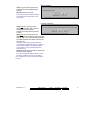
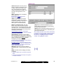
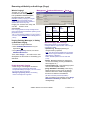
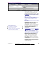
Logical Tree View?
No
Yes ( 9 )
You can customize the look and content of the MyTools
bar to your own preferences . For details, refer to
"Customizing the MyTools Bar".
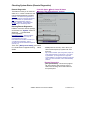
Setting Accounts to Appear in the Tree
(Multi-Account Systems)
Account folders appear in th e 'tree' (left s ide of
your screen), w hile account s are listed in the
centre portion of the screen, and can optionally
be set to appear in the tree as well.
Show Accounts in Tree:
Show Panel/Panel Group Information:
To set accou nts to appear in the 'tree', click
[Account Folders] in the 'tree'. Then, rig htclick within th e tree, and e nsure that Show
Accounts in Tree is selected.
Tip: This selection is also available in the View
menu when you are 'in' the Account Folders portion
of the tree.
Once you access an account (double-click the account
name), the tree will change to show the topics
associated with that specific account (admin.,
configuration, and status/control topics).
10
Listing Configuration and Control &
Status Topics in the Tree "Panel-byPanel":
1) Click your account/site button in the tree.
Multi-Account Systems: First select [Account
Folders] in the 'tree', and double-click an account.
2) Right-click a topic in the tree (or open the
View menu), and check to ensure that
Logical Tree View is not selected.
VEREX Director V4.73 User's Guide
21-0381E v4.7.3
Listing Configuration and Control &
Status Topics in the Tree as a Single
List:
1) Click your account/site button in the tree.
Multi-Account Systems: First select [Account
Folders] in the 'tree', and double-click an account.
2) Right-click a topic in the tree (or open the
View menu), and check to ensure that
Logical Tree View is selected.
To Show Panel References in the
Forms/Grid Window
(This is available only when "Logical Tree View" is in
effect.)
1) Set the tree to show items in a single list (see
previous / above).
2) Open Configuration (or Control & Status) in
the tree, and select any topic (such as
"System").
3) From the View menu, select Panel
Information, and ensure that "Show Panel /
Panel-Group Information" is selected.
Tip: The "ID and Name" selection causes the
name to be included in the 'Panel' and 'Group'
columns when working in Grid view.
21-0381E v4.7.3
Welcome
Report Control
Admin
Sys Config
Tech-Ref
11
(Right-Click an Account or Folder)
("View" menu when a Configuration
or Control & Status Topic is Selected
in the Tree)
(This is available only when "Logical Tree View" is in
effect.)
- Panel Information:
- Show Accounts in Tree (available in the 'Account
Folders' portion of the tree): 'Toggles' the tree
between showing accounts along with the
account folders in the tree, versus showing
accounts only in the centre of the screen.
For details on adding, renaming, and deleting
accounts and account folders, refer to "Working with
Accounts and Folders".
(Right-Click within the Tree
for an Account)
+ Show Panel / Panel-Group Information: Identifies
system panels and panel groups at the bottom of
configuration forms (and in grid view);
+ ID and Name: In conjunction with the setting
above, this shows the name for each system
panel and panel group (instead of ID only) when
working in Grid view.
In Forms view, selecting "Show Panel / Panel-Group
Information" always displays the ID and Name for the
panels & groups. (The "ID and Name" setting has no
effect when working in Forms view).
- Logical Tree View: 'Toggles' the tree between
listing all topics for an account (√) versus listing
the topics separately for each system panel (by
panel group).
Note: This setting mostly pertains to the "Control &
Status", and "Configuration" topics.
12
VEREX Director V4.73 User's Guide
21-0381E v4.7.3
Running Reports,
and Monitoring
System Activity
21-0381E v4.7.3
Welcome
Report
Control Admin
Sys Config
Tech-Ref
13
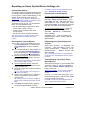
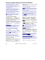
Time-and-Attendance Reporting
In/Out Status Tracking: This feature requires "User
In/Out Status Tracking" to be enabled.
Related Setting: YourAccount, ÖAccount
Information, ÖSetup (tab), Ö"Enable User In/Out
Status for this Account"
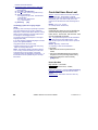
Time and Attendance Reports
Cardholder time and attendance reporting
allows generating reports pertaining t
o the
presence (roll-call), tardiness, number of hours
at w ork, etc. for users perta ining to a specific
account.
These reports are ex trapolated from entry and
exit (access g ranted) mess ages in the a ctivity
log, and compared against a selected
"attendance-period" that defines
when the
users are supposed to be inside the facility.
TechTip: Reports pertaining to past events are based
on the present event list, plus any archived data that
has been re-imported using the archive feature.
See: "Exporting or Importing Activity or Audit Logs".
For accurate attendance reporting:
• All doors used to enter and exit the facility must
have entry and exit readers.
• The site (account) must have a ‘Required
Attendance Zone’ defined by setting the "Area" as
"Outside" for all readers used to exit from this
zone.
For details, refer to "Reader 1 & 2 Settings for a
Door".
• Persons must use their access card / token
EVERY time they enter and exit the facility.
Note: Persons last reported as 'In', but with no card
activity for 24 hours will be set as 'Out'.
Attendance reports can take a full minute or longer to
appear--depending on the number of cards at the site,
and the number of activity messages being scanned.
For better performance, be sure to select the smallest
date-range that meets your requirements. Also, you
can keep the activity log to a suitable size via regular
use of the Archive and/or Purge features.
Required-Attendance Time Periods
To allow time & attendance reporting, each site
(account) must have required attendance time
periods set up that specify t he days and blocks
of time that employees are supposed to be
inside the facility.
For details, refer to "Required-Attendance Time
Periods".
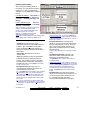
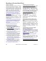
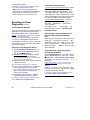
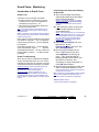
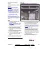
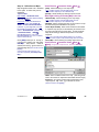
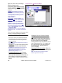
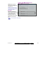
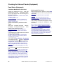
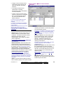
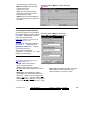
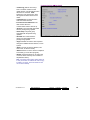
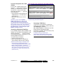
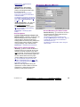
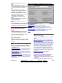
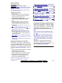
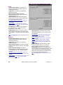
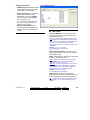
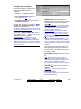
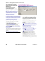
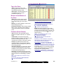
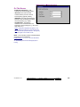
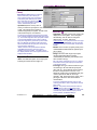
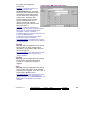
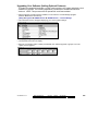
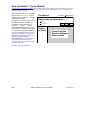
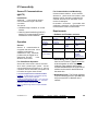
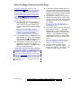
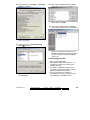
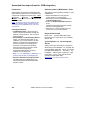
Running a Time and Attendance Report
1)
2)
3)
4)
5)
6)
7)
For details, refer to "Exporting or Importing Activity or
Audit Logs", and "Removing old Activity or Audit Logs".
Areas set for Antipassback Checking: The "APB AutoReset" feature is generally not recommended where
Time & Attendance reporting functions will be used.
For details on the 'Antipassback' feature, and the "APB
Auto-Reset" selection, refer to the "Antipassback"
settings in the "Area" configuration topic.
14
8)
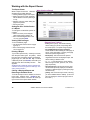
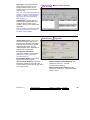
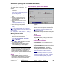
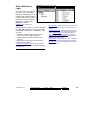
Select Time and Attendance Report from
your MyTools bar, or click [Reports] in the
'tree', and select Time and Attendance.
Multi-Account Systems: Select the desired
account near the centre of the screen.
Tip: This option appears only if you didn't already
have an account 'open' in the tree.
Select the range of dates to be covered by
the report ("From" and "To"), and the time to
be used as the "Start of Day".
Tip: See the item-descriptions for more info.
Select the desired type of report (see the
"Report Type" description for details).
Select the "Attendance period" that specifies
when persons are supposed to be in the
facility.
Notes: An attendance period is not required for
"Arrival / Departure", "Roll-Call" or "In/Out Status"
reports. If a suitable attendance-period is not
listed, refer to "Required-Attendance Time
Periods" to set one up now.
To limit the report to a specific authority,
user, etc., click [Search For], and select the
desired criteria.
Tip: To clear a selection, select it and use your
Backspace or Delete key.
Tip: You can scroll within the form to view
additional items if necessary.
Select a report 'destination' (i.e., whether it is
to be viewed, printed, or saved as a file).
If you select "Archive" or a type of "File",
click [File...], set the location and filename
as desired, and click Save.
Click [Run], and respond to any additional
screen(s) that appear (details to follow).
For details on viewing and printing displayed reports,
refer to "Working with the Report Viewer".
VEREX Director V4.73 User's Guide
21-0381E v4.7.3
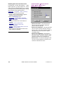
If Printing an Attendance Report
To print a report without viewing it first : Select
the type of report and other criteria as usual,
and select Printer as the destination. Then,
select Run, and click OK w hen the 'Print'
screen appea rs. Tip: To select a dif ferent
printer click Printer, and m ake your se lection
from the 'Print Setup' screen that appears.
To view a report before prin ting: Select the
type of report and other criteria as usua
l,
and select ' Screen' as t he destination.
Then, click Run.
For details on vie wing an d printing the
displayed report, refer to " Working with the
Report Viewer".
If Exporting an Attendance Report as a
File (Archive/Text File/Report Emulation
File)
Select the typ e of report an d other criteri a as
usual, and
the desired file-type a s the
'destination'. Then, click [File...]. In the next
screen, set the location
and filena me as
desired, and click Save when finished. Then
click Run.
Viewing/Printing a Previously Saved
Attendance Report-Archive
Select Time and Atten dance Repor t from
your MyTools bar, or click [Repor ts] in the
'tree', and s elect Time and
Attendance.
Then, click [Load ar chived r eport] at the
bottom of the form (scroll down if necessary).
Multi-Account Systems: You do not have to select an
account since that was done when the report was
archived.
In the ne xt screen, locat e and sele ct the
desired archived report ( .raf), and click Open
(or simply double-click the file).
For details on viewing and printing displayed reports,
refer to "Working with the Report Viewer".
21-0381E v4.7.3
Welcome
Report
Control Admin
Sys Config
Tech-Ref
15
v4.61: After selecting "Report Type: Roll Call", select
"System" (system-wide), or an individual area, as
desired. (If you select "System", the report will list
persons on an area-by-area basis.)
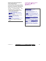
Report Period
- From and To (date): The beginning and end
date from the event log to be checked for
cardholder activity. (Change the values
manually, or click the arrow to access a pop-up
calendar.)
Note: Roll-call and In/Out status reports use the
previous 48 hours as a date/time range (instead of the
"From" and "To" settings).
- Start of Day: This setting allows shifts that
span midnight to be handled properly. Leave
this as 12:00 AM for all work shifts that begin
and end on the same day. For a shift that spans
midnight, select a time at some midpoint
between the end of one shift and the beginning
of the next one (perhaps 1:00 PM).
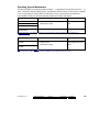
Report Type
(and Strict Interval / Relaxed Interval)
- Absentee: Persons who were not present
during some part of each specific time interval of
the required-attendance period.
Exception: With "Relaxed Interval", only persons
absent for the whole day are listed (if two intervals,
both will be reported the same).
- Arrival/Departure: The time of the first arrival
and last departure for all persons present on
each day covered by the report.
- Early Departure: Persons who left before the
end of one or more time intervals of the
required-attendance period.
- In/Out Status: A list of all users, showing
whether they are presently tracked as being
inside or outside of the facility's requiredattendance zone (see note).
Tip: Persons last reported as 'In', but with no card
activity for 24 hours will be set as 'Out'.
Note: For details on setting up a ‘Required
Attendance Zone’, refer to "Reader 1 & 2 Settings for
a Door".
Attendance Period
A time period (previously-defined) that specifies
when persons are required to be inside the
facility.
An attendance period is not required for
"Arrival/Departure", "Roll-Call" or "In/Out Status"
reports. To set up an attendance period, refer to
"Required-Attendance Time Periods".
[Search For] / [Clear Search]
- This displays or closes the centre of the screen,
which contains selections for 'fine-tuning' the
report to a specific person, or users with a
certain authority-profile or other criteria.
To clear a selection: Select it and use your
Backspace or Delete key.
Searching by Name: For reports that allow searching
by user-name, you can enter the 1st or last name
only, 1st and last name (separated with a space), or
"LastName, 1stName". If searching for a first or last
name, you can enter the first few characters plus an
asterisk (e.g., nam*).
Note: With "Strict Interval", persons who leave during
a required time-interval, and then return after-hours
(on the same workday) are treated as early
departures. Select "Relaxed Interval" to stop this.
- Late Arrival: Persons who arrived after the
beginning of one or more time intervals of the
required-attendance period.
Note: With "Strict Interval", persons who arrive and
leave beforehand (on the same workday) and then
return during a required time interval are treated as
late arrivals. Select "Relaxed Interval" to stop this.
- Totalization: The duration each person spent
inside the facility on each day during the
required-attendance times.
- Roll Call: All persons presently tracked as
being inside the facility's required-attendance
zone (see note);
16
VEREX Director V4.73 User's Guide
21-0381E v4.7.3
Custom User Field: This pertains to
(optional) custom user information
categories that can appear at the bottom of
the 'User' screen.
Note: Reports cannot be filtered on multiline fields. Be sure to make your selection
with this in mind.
Past Employees Deleted from the System:
You can type a name rather than selecting
it. This allows running a report on persons
(and/or items) that have been recently
deleted.
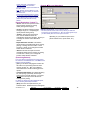
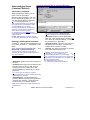
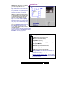
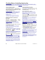
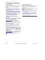
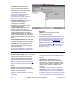
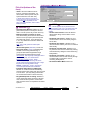
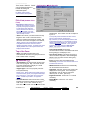
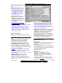
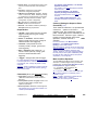
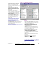
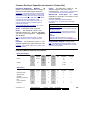
Reports ÖTime and Attendance
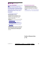
Report Destination / Output To
- Screen: This has the report sent to the
'Report Viewer' window for viewing
and/or printing desired pages;
- Printer: This allows selecting a printer (Multi-Account Systems: Account Selection 'Tree')
and page-range, etc., and printing the
- This area (near the centre of the screen) is where you select the
account that your report pertains to. Tip: This option appears only if
report (without viewing it first);
you didn't already have an account 'open' in the tree.
- Text File: This has the report saved
as a 'comma-delimited' text file for
depending on your selections (such as the
manipulation with another program. Allows you
printer selection form, report viewer, etc.).
to change the location and/or filename if
desired.
- Report Emulation Text File: This has the
report saved as a formatted text file for viewing,
printing, or editing with a text editor or word
processor. Allows you to change the location
and/or filename if desired.
- Archive: This has the report saved as a
viewable archived report for viewing or printing
at a later time. Allows you to change the
location and/or filename if desired.
(Remaining Buttons)
(You may need to scroll within the form and/or resize
the window to view additional items. Click Reset on the
toolbar to reset the desktop.)
- [File...]: This allows changing the location and
file-name for a report being saved for future
viewing, printing, etc. Tip: Use a different
name each time to avoid overwriting previous
reports.
- [Load Archived Report]: This allows browsing
for, and opening a previously saved reportarchive (not for use with text files). The report
will appear in the report-viewer window for
viewing and/or printing.
For details on viewing and printing displayed reports,
refer to "Working with the Report Viewer".
- [Run]: This runs the report based on your
selected criteria. Additional screens will appear
21-0381E v4.7.3
Welcome
Report
Control Admin
Sys Config
Tech-Ref
17
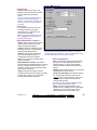
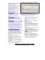
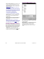
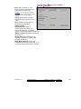
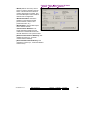
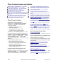
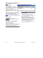
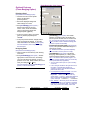
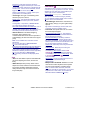
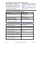
Required-Attendance Time-Periods
Attendance Periods
Attendance p eriods are w eekly blocks of time
that allow tim e & attendance reports to 'k now'
when users are supposed to be in the facility.
Schedules for cardholder access must span a larger
period of time than the applicable attendance period--to
let people enter the facility before their shift begins, and
leave after it ends.
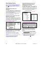
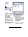
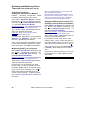
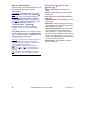
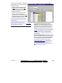
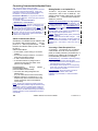
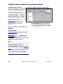
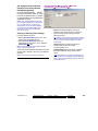
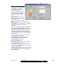
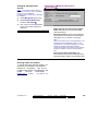
Adding (Setting up) an Attendance
Period
Select Attendance P eriod from your MyTools
bar, or click [Repor ts] in the 'tree', open the
Time and Attendance branch, and select
Attendance Period.
Multi-Account Systems: Select the desired account
near the centre of the screen. Tip: This option
appears only if you didn't already have an account
'open' in the tree.
Now, cli ck [+] at the botto m of the for m, or
right-click the form, and select Add Ne w from
the pop-up menu.
Alternative: You can also select a blank/grey item from
the list (bottom of the form). Note: Grid view does not
apply to this screen.
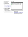
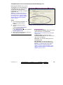
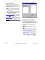
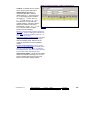
The attendance period is shown graphically,
for Sunday through Saturday. Add a new timeinterval by right-clicking a specific day, and
selecting Create New Time Interval.
Then, drag th e interval and/or its end-poin ts to
the desired lo cation. Tip: Copying, pa sting,
and deleting is also allo wed w hen you r ightclick a specific time-interval.
Repeat this process until the desired times are
set up for all days in the attendance period.
(You can use up to 6 uni
que time intervals
throughout each schedule.)
Now refer to t he selection-descriptions for this
screen for additional information.
Viewing or Changing Settings for a
Required-Attendance Period
Select Attendance P eriod from your MyTools
bar, or click [Repor ts] in the 'tree', open the
Time and Attendance branch, and select
Attendance Period.
Multi-Account Systems: Select the desired account
near the centre of the screen.
Now, choos e the desired attendance p eriod
from the list ( bottom of the form), and refer to
the selection- descriptions f or this screen while
viewing and/or changing settings as desired.
Deleting an Attendance Period
Select Attendance P eriod from your MyTools
bar, or click [Repor ts] in the 'tree', open the
Time and Attendance branch, and select
Attendance Period.
Multi-Account Systems: Select the desired account
near the centre of the screen.
Now, choos e the desired attendance p eriod
from the list ( bottom of the form). Then, rightclick a blank area near the bottom, and select
Delete. When asked to confirm, choose Yes.
Tip: You can copy all settings for an attendance
st
period, and paste them into another one: In the 1 one,
right-click near the bottom of the form, and select Copy.
Then, select a blank/new attendance period from the
list, right-click near the bottom of the form, and select
Paste. After 'pasting', change the name and any
settings as desired. Note: 'Copy' and 'Paste' are also
available from the Edit menu.
18
VEREX Director V4.73 User's Guide
21-0381E v4.7.3
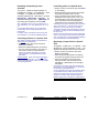
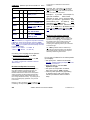
Reports ÖTime and Attendance ÖAttendance Period
Pick-Lists (bottom of the
Form)
- Attendance Period (bottom of form):
This is where you select an attendance
period to view or edit. This area
shows a reference number assigned
by the system, and the name of the
attendance period, once defined;
Top of the Form
- Name: A suitable name/description for
the attendance period, or its intended
use;
(Multi-Account Systems: Account Selection 'Tree')
- This area (near the centre of the screen) is where you select the
account that your attendance-period pertains to. Tip: This option
appears only if you didn't already have an account 'open' in the tree.
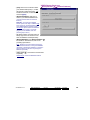
On this Form (Intervals )
- Days of the Week (with Associated TimeIntervals): The days of the week showing the
time intervals for each day. (To add an
interval, right-click the specific day. To adjust
an interval, drag the interval and/or its endpoints to the desired position.)
Tips: You can copy and paste (or delete) time
intervals using the right-click menu. Up to 6 unique
time-intervals can be used as desired throughout the
weekdays in each attendance period.
Split Shift: Be sure to include an interval for after a
meal break—assuming the break is not part of the
'required attendance' times.
Work Shift that Spans Midnight: In this case, each day
will need two intervals for the times before and after
midnight, plus any other required intervals (such as for
after a meal break—assuming the break is not part of
the 'required attendance' times).
21-0381E v4.7.3
Welcome
Report
Control Admin
Sys Config
Tech-Ref
19
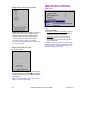
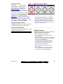
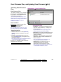
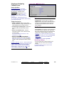
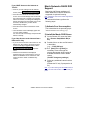
Roll-Call Reports (v4.61)
In/Out Status Tracking: This feature
requires "User In/Out Status Tracking" to be
enabled.
Related Setting: YourAccount, ÖAccount
Information, ÖSetup (tab), Ö"Enable User
In/Out Status for this Account"
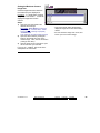
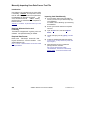
An instant roll-call feature has been
added to the status toolbar.
This sends a roll-call report for your
monitored account to your default Windows
printer.
(The report will list persons on an area-byarea basis.)
Note: A communications session with the
applicable panel(s) must be in effect.
To start a communications session:
1) Select Communications from your MyTools bar, or
click [Communications] in the 'tree', and select
Pending/OnLine. 2) Click [Edit], and make your
selections from the screen that appears.
Tip: Once there, you can open the online help at the
applicable topic by pressing F1.
To set or change the account to be monitored:
1) Click [Monitor] near the far-right end of the toolbar;
2) Make your selections from the screen that appears.
To select a default printer under MS Windows:
1) Go to your Windows "Control Panel"; 2) Double-click
"Printers and Faxes"; 3) Double-click the desired
printer.
As well, "Time and Attendan ce - Rol l-Call"
reports can now be run on individual areas.
20
VEREX Director V4.73 User's Guide
21-0381E v4.7.3
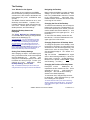
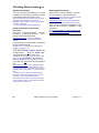
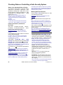
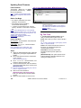
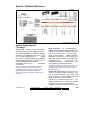
Reporting on System & Personnel Activity
screen(s) that appear (details to follow).
Activity Reports
Activity reporting allo ws vie wing or printing a
listing of various types of events that have
occurred for a specific a ccount. A date /time
range can be specified, and the report can also
be limited to a specific are a, device, per son,
etc.
TechTip: Reports pertaining to past events are based
on the present event list, plus any archived data that
has been re-imported using the archive feature.
See: "Exporting or Importing Activity or Audit Logs".
As well, a ctivity reports can be vie wed a nd/or
printed right a way, saved for future reference,
or ex ported for manipulation w
ith ano ther
program.
For better performance, activity reports cover only the
latest 5000 messages in the activity log. For even
faster execution, keep the activity log to a suitable size
via regular use of the Archive and/or Purge features.
See: "Exporting or Importing Activity or Audit Logs",
and "Removing old Activity or Audit Logs".
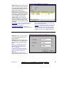
Running an Activity Report
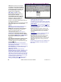
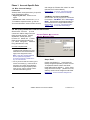
1) Select Activity Report from your MyTools
bar, or click [Reports] in the 'tree', and select
Activity.
2) Multi-Account Systems: Select the desired
account near the centre of the screen.
For details on viewing and printing displayed reports,
refer to "Working with the Report Viewer".
If Printing an Activity Report
To print a report without viewing it first : Select
the type of report and other criteria as usual,
and select Printer as the destination. Then,
select Run, and click OK w hen the 'Print'
screen appea rs. Tip: To select a dif ferent
printer click Printer, and m ake your se lection
from the 'Print Setup' screen that appears.
To view a report before prin ting: Select the
type of report and other criteria as usua
l,
and select ' Screen' as t he destination.
Then, click Run.
For details on vie wing an d printing the
displayed report, refer to " Working with the
Report Viewer".
If Exporting an Activity Report as a File
(Archive/Text File/Report Emulation
File)
Tip: This option appears only if you didn't already
have an account 'open' in the tree.
Select the typ e of report an d other criteri a as
usual, and
the desired file-type a s the
'destination'. Then, click [File...]. In the next
screen, set the location
and filena me as
desired, and click Save when finished. Then
click Run.
Tip: See the item-descriptions if you need help.
Viewing/Printing a Previously Saved
Activity Report-Archive
3) Select the date/time range to be covered by
the report (under "From" and "To").
4) Select the types of events to be included in
the report (you must select at least one).
5) To limit the report to a specific person, area,
door, etc., click [Search For], and select the
desired criteria.
To clear an individual selection, select it and use
your Backspace or Delete key. To reset/clear all
selections, scroll down and click [Reset].
Tip: You can scroll within the form to view
additional items if necessary.
6) Select a report 'destination' (i.e., whether it is
to be viewed, printed, or saved as a file).
If you select "Archive" or a type of "File", click
[File...], set the location and filename as
desired, and click Save.
7) Click [Run], and respond to any additional
21-0381E v4.7.3
Welcome
Report
Select Activity Report from your MyTools bar,
or click [Repor ts] in the 'tree', and select
Activity. The n, click [Load ar chived r eport]
at the botto m of the form (scroll dow
n if
necessary).
Multi-Account Systems: You do not have to select an
account since that was done when the report was
archived.
In the ne xt screen, locat e and sele ct the
desired archived report ( .raf), and click Open
(or simply double-click the file).
For details on viewing and printing displayed reports,
refer to "Working with the Report Viewer".
Control Admin
Sys Config
Tech-Ref
21
Event Period
- From and To (date and time): The beginning
and end date from the event log to be checked
for cardholder activity.
Tip: You can change the dates manually, or click the
arrow to access a pop-up calendar. To set the times,
click within the 'hours' or 'minutes', and use the
up/down arrow keys.
Event Type
- The various types of messages that can be
included in the report (select the ones that you
want included).
Note: You must select at least one event-type.
"Toggle All" allows selecting or de-selecting all eventtypes.
[Search For] / [Clear Search]
- This displays or closes the centre of the screen,
which contains selections for 'fine-tuning' the
report to a specific person, area, door, etc.
Custom User Field: This pertains to (optional) custom
user information categories that can appear at the
bottom of the 'User' screen.
Note: Reports cannot be filtered on multi-line fields.
Be sure to make your selection with this in mind.
Show on Resolution: This lets you have the list include
events depending on whether or not they have been
'resolved' (i.e., dealt-with). "All": This shows all
events--including ones not associated with the
comment/resolution feature.
For details on resolving events, refer to "Dealing with
Alarms (Comment / Resolve)" in the section on
monitoring activity (previous).
Show on Priority: This allows limiting the window to
show only events of a desired priority value (or range).
Show on Custom Filter: This allows limiting the
window to show only events of a desired 'custom-filter'
value (or range).
Also See: To assign priorities or 'Custom Filter'
values, refer to the configuration topic: "Customizing
How Events are Displayed".
Tip: To clear an individual selection, select it and use
your Backspace or Delete key. To reset/clear all
selections, click the [Reset] button at the bottom of
the form (scroll down if this button is not visible).
Past Employees Deleted from the System: You can
type a name rather than selecting it. This allows
running a report on persons (and/or items) that have
been recently deleted.
Report Destination / Output To
- Screen: This has the report sent to the 'Report
Viewer' window for viewing and/or printing
22
VEREX Director V4.73 User's Guide
21-0381E v4.7.3
desired pages;
- Printer: This allows selecting a printer
and page-range, etc., and printing the
report (without viewing it first);
- Text File: This has the report saved
as a 'comma-delimited' text file for
manipulation with another program.
Allows you to change the location
and/or filename if desired.
- Report Emulation Text File: This has
the report saved as a formatted text
file for viewing, printing, or editing with
a text editor or word processor.
Allows you to change the location
and/or filename if desired.
- Archive: This has the report saved as
a viewable archived report for viewing
or printing at a later time. Allows you
to change the location and/or filename
if desired.
Reports ÖActivity
(Remaining Buttons)
Tip: You can scroll within the form and/or
resize the window to view additional items
when necessary. (Click Reset on the
toolbar to reset the desktop.)
(Multi-Account Systems: Account Selection 'Tree')
- This area (near the centre of the screen) is where you select the
account that your report pertains to. Tip: This option appears only if
you didn't already have an account 'open' in the tree.
- [File...]: This allows changing the
location and file-name for a report
being saved for future viewing,
printing, etc. Tip: Use a different name each
time to avoid overwriting previous reports.
- [Reset]: This provides a quick way to reset/clear
the "Search for" criteria and other selections on
the form.
- [Load Archived Report]: This allows browsing
for, and opening a previously saved reportarchive (not for use with text files). The report
will appear in the report-viewer window for
viewing and/or printing.
For details on viewing and printing displayed reports,
refer to "Working with the Report Viewer".
- [Run]: This runs the report based on your
selected criteria. Additional screens will appear
depending on your selections (such as the
printer selection form, report viewer, etc.).
21-0381E v4.7.3
Welcome
Report
Control Admin
Sys Config
Tech-Ref
23
Reporting on Previous Guard-Tours
Guard Tour Reports
If Printing a Guard Tour Report
Guard tour reports allo w view ing or print ing a
listing of events pertaining to previous
guard
tours for a specific account. A date/time r ange
can be specif ied, and the r eport can als o be
limited to sp ecific items s uch as guard tour
alarms, or the guard arriving early or late.
To print a report without viewing it first : Select
the type of report and other criteria as usual,
and select Printer as the destination. Then,
select Run, and click OK w hen the 'Print'
screen appea rs. Tip: To select a dif ferent
printer click Printer, and m ake your se lection
from the 'Print Setup' screen that appears.
To view a report before prin ting: Select the
type of report and other criteria as usua
l,
and select ' Screen' as t he destination.
Then, click Run.
For details on vie wing an d printing the
displayed report, refer to " Working with the
Report Viewer".
TechTip: Reports pertaining to past events are based
on the present event list, plus any archived data that
has been re-imported using the archive feature.
See: "Exporting or Importing Activity or Audit Logs".
Active Guard Tours: For details on monitoring a guardtour, refer to "Guard Tours".
As well, guar d tour reports can be
vie wed
and/or printe d right aw ay, saved for f uture
reference, or e xported for manipulation with
another program.
For better performance, activity and guard-tour reports
cover only the latest 5000 messages in the activity log.
For even faster execution, keep the activity log to a
suitable size via regular use of the Archive and/or
Purge features.
See: "Exporting or Importing Activity or Audit Logs",
and "Removing old Activity or Audit Logs".
Running a Guard Tour Report
1) Select Guard Tour Report from your
MyTools bar, or click [Reports] in the 'tree',
and select Guard Tour.
2) Multi-Account Systems: Select the desired
account near the centre of the screen.
Tip: This option appears only if you didn't already
have an account 'open' in the tree.
3) Select the date/time range to be covered by
the report (under "From" and "To").
Tip: See the item-descriptions if you need help.
4) Select the types of events to be included in
the report (you must select at least one).
5) Select a report 'destination' (i.e., whether it is
to be viewed, printed, or saved as a file).
If you select "Archive" or a type of "File", click
[File...], set the location and filename as
desired, and click Save.
6) Click [Run], and respond to any additional
screen(s) that appear (details to follow).
If Exporting a Guard Tour Report as a
File (Archive/Text File/Report Emulation
File)
Select the typ e of report an d other criteri a as
usual, and
the desired file-type a s the
'destination'. Then, click [File...]. In the next
screen, set the location
and filena me as
desired, and click Save when finished. Then
click Run.
Viewing/Printing a Previously Saved
Guard Tour Report-Archive
Select Guard Tour Report from your MyTools
bar, or click [Repor ts] in the 'tree', and select
Guard Tour . Then, clic k [Load archi ved
report] at the bottom of the form.
Multi-Account Systems: You do not have to select an
account since that was done when the report was
archived.
In the ne xt screen, locat e and sele ct the
desired archived report ( .raf), and click Open
(or simply double-click the file).
For details on viewing and printing displayed reports,
refer to "Working with the Report Viewer".
For details on viewing and printing displayed reports,
refer to "Working with the Report Viewer".
24
VEREX Director V4.73 User's Guide
21-0381E v4.7.3
Reports ÖGuard Tour
Event Period
- From and To (date and time): The
beginning and end date from the event
log to be checked for guard-tour
events.
Tip: You can change the dates manually,
or click the arrow to access a pop-up
calendar. To set the times, click within the
'hours' or 'minutes', and use the up/down
arrow keys.
Event Type
- The various guard tour events to be
included in the report (the guard
arriving late, etc.). Select the ones
that you want included).
Note: You must select at least one eventtype. "Toggle All" allows selecting or deselecting all event-types.
Report Destination / Output To
- Screen: This has the report sent to the
'Report Viewer' window for viewing
and/or printing desired pages;
- Printer: This allows selecting a printer
and page-range, etc., and printing the
(Multi-Account Systems: Account Selection 'Tree')
report (without viewing it first);
- This area (near the centre of the screen) is where you select the
account that your report pertains to. Tip: This option appears only if
- Text File: This has the report saved
you didn't already have an account 'open' in the tree.
as a 'comma-delimited' text file for
manipulation with another program.
Allows you to change the location and/or
(Remaining Buttons)
filename if desired.
- [File...]: This allows changing the location and
file-name for a report being saved for future
- Report Emulation Text File: This has the
viewing, printing, etc. Tip: Use a different
report saved as a formatted text file for viewing,
name each time to avoid overwriting previous
printing, or editing with a text editor or word
reports.
processor. Allows you to change the location
and/or filename if desired.
- [Reset]: This provides a quick way to reset/clear
all selected items on the screen.
- Archive: This has the report saved as a
viewable archived report for viewing or printing
- [Load Archived Report]: This allows browsing
at a later time. Allows you to change the
for, and opening a previously saved reportlocation and/or filename if desired.
archive (not for use with text files). The report
will appear in the report-viewer window for
viewing and/or printing.
For details on viewing and printing displayed reports,
refer to "Working with the Report Viewer".
- [Run]: This runs the report based on your
selected criteria. Additional screens will appear
depending on your selections (such as the
printer selection form, report viewer, etc.).
21-0381E v4.7.3
Welcome
Report
Control Admin
Sys Config
Tech-Ref
25
Reporting on User Access Authorities (by Area, Door, or Floor)
User Access Reports
User-access reports provide a list of
the
persons with authority to access a specific
area, door, or floor on spec ific weekdays and
times. You can also list:
• Cards that have
expired; • Cards that w ill ex pire in the future
(selectable date-range); • Cards that have not
been used since a specific date;
• Cards
identified as being 'Lost'.
Related: Users, ÖLost Cards
Cards that have been Lost
Tip: This is a powerful report that checks more than
schedules and area assignments. It also checks things
like "Master Override", scheduled door unlockings, etc.
Note: This report pertains to users who are intended
to have access based on system configuration. (It
cannot allow for things such as manual door
unlockings.)
User-access reports can be vie wed a nd/or
printed right a way, saved for future reference,
or ex ported for manipulation w
ith ano ther
program.
Running a User-Access Report
1)
Select User Access Report from your
MyTools bar, or click [Reports] in the 'tree',
and select User Access.
2)
Multi-Account Systems: Select the desired
account near the centre of the screen.
3)
4)
Tip: This option appears only if you didn't already
have an account 'open' in the tree.
If Exporting a Report as a File
(Archive/Text File/Report Emulation File)
Select the typ e of report an d other criteri a as
usual, and
the desired file-type a s the
'destination'. Then, click [File...]. In the next
screen, set the location
and filena me as
desired, and click
Save w hen finis hed.
Then click Run.
Viewing/Printing a Previously Saved
Report-Archive
Select User Access Report
from your
MyTools bar, or click [Rep orts] in the 't ree',
and select User Acce ss. Then, click [Load
archived rep ort] at the b ottom of the form
(scroll down if necessary).
Multi-Account Systems: You do not have to select an
account since that was done when the report was
archived.
In the ne xt screen, locat e and sele ct the
desired archived report ( .raf), and click Open
(or simply double-click the file).
Refer to the selection-descriptions for this
screen while setting up your report as
desired.
For details on viewing and printing displayed reports,
refer to "Working with the Report Viewer".
Click [Run], and respond to any additional
screen(s) that appear (details to follow).
Report Type
For details on viewing and printing displayed reports,
refer to "Working with the Report Viewer".
If Printing a User-Access Report
To print a report without viewing it first : Select
the type of report and other criteria as usual,
and select Printer as the destination. Then,
select Run, and click OK w hen the 'Print'
screen appea rs. Tip: To select a dif ferent
printer click Printer, and m ake your se lection
from the 'Print Setup' screen that appears.
26
To view a report before prin ting: Select the
type of report and other criteria as usua
l,
and select ' Screen' as t he destination.
Then, click Run.
For details on vie wing an d printing the
displayed report, refer to " Working with the
Report Viewer".
- Select the type of information to be included in
your report.
User Access to Area/Door/Floor: This lists
users/cards that have access to a specific area, door,
or floor during selected days and times.
Expired Cards: This lists cards that are presently
expired, or that will expire in the future (per your
selections). Tip: You can change the date numerals
manually, or click the arrows to access pop-up
calendars.
Inactive Cards: This lists cards that have note been
used since a selected date. Tip: You can change the
date numerals manually, or click the arrow to access a
pop-up calendar.
VEREX Director V4.73 User's Guide
21-0381E v4.7.3
Lost Cards: This lists cards that have been
identified as 'lost'. User names and IDs will
be included in the report for cards set as
'Lost' through the "Users" screen.
Related: Users, ÖLost Cards
Cards that have been Lost
Reports ÖUser Access
Time Range
- Select the time of day to be examined
for cardholder access (i.e., the starting
time and end time).
Tip: To set the times, click within the
'hours' or 'minutes', and use the up/down
arrow keys. Note: The report will include
everyone with access during any portion
of your selected time range.
Selected Days
- Select the weekdays to be examined
for cardholder access.
Note: You must select at least one
weekday. Note: The report will include
everyone with access on any of the days
you select.
(Multi-Account Systems: Account Selection 'Tree')
- Area is not scheduled, list users
- This area (near the centre of the screen) is where you select the
account that your report pertains to. Tip: This option appears only if
with access when area is off: This
you didn't already have an account 'open' in the tree.
causes the report to disregard if the
area is presently armed.
viewable archived report for viewing or printing
- Process Authority Plus: Select this for users
at a later time. Allows you to change the
that may have a second authority assigned
location and/or filename if desired.
(authority plus).
(Remaining Buttons)
- Custom User Field x: This allows selecting
one or two custom user fields to be included in
the report.
Note: These cannot be multi-line fields.
Report Destination / Output To
- Screen: This has the report sent to the 'Report
Viewer' window for viewing and/or printing
desired pages;
- Printer: This allows selecting a printer and
page-range, etc., and printing the report (without
viewing it first);
- Text File: This has the report saved as a
'comma-delimited' text file for manipulation with
another program. Allows you to change the
location and/or filename if desired.
- Report Emulation Text File: This has the
report saved as a formatted text file for viewing,
printing, or editing with a text editor or word
processor. Allows you to change the location
and/or filename if desired.
- Archive: This has the report saved as a
21-0381E v4.7.3
Welcome
Report
- [File...]: This allows changing the location and
file-name for a report being saved for future
viewing, printing, etc. Tip: Use a different
name each time to avoid overwriting previous
reports.
- [Reset]: This provides a quick way to reset/clear
the "Search for" criteria and other selections on
the form.
- [Load Archived Report]: This allows browsing
for, and opening a previously saved reportarchive (not for use with text files). The report
will appear in the report-viewer window for
viewing and/or printing.
For details on viewing and printing displayed reports,
refer to "Working with the Report Viewer".
- [Run]: This runs the report based on your
selected criteria. Additional screens will appear
depending on your selections (such as the
printer selection form, report viewer, etc.).
Control Admin
Sys Config
Tech-Ref
27
Reporting on Users, System/Device Settings, etc.
Customizable Reports
The VEREX Director soft ware allo ws vie wing
or printing a listing of programmed information
in your syste m. This inc ludes settings f or the
system, areas, devices, panel users, etc.
Related Topic: You can also link to the database and
set up custom queries of nearly any scope and content.
Details: Advanced Database Features
These report s sho w a lis t of your selected
items, in a customizable format:
• Set the fields/settings to appear in the report,
and the order of these 'columns';
• Include only the users/items that match
specific criteria;
• Set the sort order for the listed users/items.
Tip: These reports can also be saved as a 'commadelimited' text file for manipulation with another
program.
Running these Types of Reports
1a) To view or print a customizable list of users,
select User Report from your MyTools bar,
or click [Reports] in the 'tree', and select
Users .
1b) For a customizable list of other programmed
items, select Panel Configuration Report
from your MyTools bar, or click [Reports] in
the 'tree', and select Panel Configuration.
2) Multi-Account Systems: Select the desired
account in the account selection 'tree' near
the centre of the screen.
3)
4)
5)
6)
28
Tip: This option appears only if you didn't already
have an account 'open' in the tree.
Panel Configuration Reports: Select the
"Type" of report (e.g., list settings for areas,
doors, schedules, etc.).
Select the columns of items to be included in
the report ( 9 ).
Tip: For more information, refer to "Columns" in
the selection-descriptions.
Select a report 'destination' (i.e., whether the
report is to be viewed, or printed without
viewing it first).
Tip: If saving a report as a text file, click [File...],
set the location and filename as desired, and click
Save.
For details on viewing and printing displayed reports,
refer to "Working with the Report Viewer".
If Printing one of These Reports
To print a report without viewing it first : Select
the type of report and other criteria as usual,
and select Printer as the destination. Then,
select Run, and click OK w hen the 'Print'
screen appea rs. Tip: To select a dif ferent
printer click Printer, and m ake your se lection
from the 'Print Setup' screen that appears.
To view a report before prin ting: Select the
type of report and other criteria as usua
l,
and select ' Screen' as t he destination.
Then, click Run.
For details on vie wing an d printing the
displayed report, refer to " Working with the
Report Viewer".
If Exporting one of these Reports as a
Text File
Select "User", and set t
he 'destinatio n' as
"Text File ". Then, click [File...]. In the nex t
screen, set the location
and filena me as
desired, and click
Save w hen finis hed.
Then click Run.
Tip: The report will be saved as a 'comma-delimited'
text file that can be manipulated with another program
as desired.
Viewing/Printing a Previously Saved
Report-Archive
Select the de sired type of r eport as desc ribed
previously ("Users", or "Panel Configuration").
Then, click [Load ar chived r eport] at the
bottom of the form.
Multi-Account Systems: You do not have to select an
account since that was done when the report was
archived.
In the ne xt screen, locat e and sele ct the
desired archived report ( .raf), and click Open
(or simply double-click the file).
For details on viewing and printing displayed reports,
refer to "Working with the Report Viewer".
Click [Run], and respond to any additional
screen(s) that appear (details to follow).
VEREX Director V4.73 User's Guide
21-0381E v4.7.3
- Type (Panel Config. Reports only):
The desired topic to be covered by the
report (areas, doors, etc.).
Reports ÖUsers;
Reports ÖPanel Configuration
Note: Reports pertaining to "Areas" and
physical devices (modules, doors, etc.) are
available only for operators with the
applicable 'Configuration' permissions.
- (Columns): Data fields/settings to be
included in the report.
Tip: The "Group" column in panel config.
reports pertains to the "Panel Group" (e.g.,
location) for the specific panel.
Set the Column Order: To change the
position of a column, click the column once
(Multi-Account Systems: Account Selection 'Tree')
to select it, and then click-and-drag it to the - This area (near the centre of the screen) is where you select the
new location. Tip: You can use the
account that your report pertains to. Tip: This option appears only if
horizontal scroll-bar to view additional
you didn't already have an account 'open' in the tree.
columns.
Select Desired Columns: Click the checkmanipulation with another program. Allows you
box for each column to appear in the report ( 9 ).
to change the location and/or filename if
Tip: You will be notified if you selected more than
desired.
can fit in the space available (de-select some if
required).
Note: Any custom user categories (department,
Setting the Sort-Order: To sort the report by any one
position, etc.) set as the "Memo" data type (multi-line
value (such as last name), open the 'sort' box for the
edit) will be omitted.
desired column (click the down arrow), and select the
(Remaining Buttons)
desired sort order (ascending or descending).
- [File...]: This allows changing the location and
Limiting to People/Items that match some Criteria: To
file-name for a report being saved for future
limit the report to persons/items that match a specific
viewing, printing, etc. Tip: Use a different
value (authority, custom user category, etc.), open the
'filter' box for the desired column (click the down
name each time to avoid overwriting previous
arrow), and select an item from the list. Tip: You can
reports.
filter on multiple columns if desired. Note: Reports
[Reset]: This provides a quick way to reset/clear
cannot be filtered on multi-line fields. Be sure to make
all selected items on the screen.
your selection with this in mind.
"Input Point" Panel Configuration Reports: To allow
- [Load Archived Report]: This allows browsing
reporting on input points for a specific panel, filtering
for, and opening a previously saved reportmust be selected for the applicable panel group first.
archive (not for use with text files). The report
This will enable the "Panel" filtering checkbox to
will appear in the report-viewer window for
allow selecting a specific panel. - [Select
All
Data] and [Clear All Data]: These buttons
allow selecting or deselecting all fields/columns
for the report.
Report Destination / Output To
- Screen: This has the report sent to the 'Report
Viewer' window for viewing and/or printing
desired pages;
- Printer: This allows selecting a printer and
page-range, etc., and printing the report (without
viewing it first).
- Text File (for User reports): This has the report
saved as a 'comma-delimited' text file for
21-0381E v4.7.3
Welcome
Report
viewing and/or printing.
- [Run]: This runs the report based on your
selected criteria. Additional screens will appear
depending on your selections (such as the
printer selection form, report viewer, etc.).
For details on viewing and printing displayed reports,
refer to "Working with the Report Viewer".
Control Admin
Sys Config
Tech-Ref
29
Reporting on Operator Audits or Panel Communications Logs
Audit Reports
Audit reporting allows vie wing or printing a
listing of changes made by operators, or
records of panel communic ations sessions. A
date/time range can be specified, and
the
report can also be limited to desired criteria.
TechTip: Reports pertaining to past events are based
on the present event list, plus any archived data that
has been re-imported using the archive feature.
See: "Exporting or Importing Activity or Audit Logs".
As well, audit reports can be vie wed an d/or
printed right a way, saved for future reference,
or ex ported for manipulation w
ith ano ther
program.
For better performance, be sure to select the smallest
date-range that meets your requirements. Also, you
can keep the audit log to a suitable size via regular use
of the Archive and/or Purge features.
See: "Exporting or Importing Activity or Audit Logs",
and "Removing old Activity or Audit Logs".
Running an Audit Report
1) Select Audit Report from your MyTools bar,
or click [Reports] in the 'tree', and select
Audit Report.
2) Select the date/time range to be covered by
the report (under "From" and "To").
Tip: See the item-descriptions if you need help.
3) Select the desired criteria for the report.
If Exporting an Audit Report as a File
(Archive/Text File/Report Emulation
File)
Select the typ e of report an d other criteri a as
usual, and
the desired file-type a s the
'destination'. Then, click [File...]. In the next
screen, set the location
and filena me as
desired, and click
Save w hen finis hed.
Then click Run.
Viewing/Printing a Previously Saved
Audit Report-Archive
Select Audit Repor t from your MyTools bar,
or click [Repor ts] in the 'tree', and select
Audit Repor t. Then, clic k [Load archi ved
report] at the bottom of the form.
In the ne xt screen, locat e and sele ct the
desired archived report ( .raf), and click Open
(or simply double-click the file).
(Refer to the details under "Search Criteria".)
For details on viewing and printing displayed reports,
refer to "Working with the Report Viewer".
If you select "Archive" or a type of "File", click
[File...], set the location and filename as desired,
and click Save.
Log Period
4) Select a report 'destination' (i.e., whether it is
to be viewed, printed, or saved as a file).
5) Click [Run], and respond to any additional
screen(s) that appear (details to follow).
For details on viewing and printing displayed reports,
refer to "Working with the Report Viewer".
If Printing an Audit Report
To print a report without viewing it first : Select
the type of report and other criteria as usual,
and select Printer as the destination. Then,
select Run, and click OK w hen the 'Print'
screen appea rs. Tip: To select a dif ferent
printer click Printer, and m ake your se lection
from the 'Print Setup' screen that appears.
30
To view a report before prin ting: Select the
type of report and other criteria as usua
l,
and select ' Screen' as t he destination.
Then, click Run.
For details on vie wing an d printing the
displayed report, refer to " Working with the
Report Viewer".
- From and To (date and time): The beginning
and end date from the audit log to be scanned
for the report.
Tip: You can change the dates manually, or click the
arrow to access a pop-up calendar. To set the times,
click within the 'hours' or 'minutes', and use the
up/down arrow keys.
Client/Server Systems: Times are stored as GMT in
the database, and adjusted for correct display in the
time-zone at each specific workstation.
Search Criteria
- Log Type: Select "Operator" for configuration
changes made by operator(s), or
"Communication" for panel update sessions.
VEREX Director V4.73 User's Guide
21-0381E v4.7.3
- Account: Select a specific account,
or "All" accounts.
- Action: This changes depending on
the type of report:
Reports ÖAudit Report
For an Operator audit report: The type of
action that was performed (add, delete,
etc.). "All" is recommended here, unless
you're looking for something more specific.
For a Communications Log Report: The
type of communications session
(normal/sync , get from panel, or send to
panel).
- Operator (operator audit report only):
Select a desired operator, or "All" for
audits by any operator.
- Topic (operator audit report only): This is
the type of information that was
changed. Select "All" for changes
made to any topic.
Report Options
- Show Transaction Date/Time (for
communication logs): The date and time
for each communications event will be
shown only if this is selected (9).
- Show Transaction Details (for
operator logs): Selecting this (9) will
cause details for user and operator
audits to be included in the report.
(Multi-Account Systems: Account Selection 'Tree')
- The area (near the centre of the screen) is where you select the
account that your report pertains to. Tip: This option appears only if
you didn't already have an account 'open' in the tree.
Note: This data will be available for reporting only if
this feature is turned on under “[Management],
ÖReporting”.
Details: Detailed Operator and User Audit Trail
(≥V4.6)
Director-Server Language: Some of the detailed audit
text comes through the Director-server. To
temporarily set it to a specific language, right-click the
Director-Server keypad/folder icon near the right-hand
end of the Windows taskbar, and make your selection
under “Language”.
Report Destination / Output To
- Screen: This has the report sent to the 'Report
Viewer' window for viewing and/or printing
desired pages;
- Printer: This allows selecting a printer and
page-range, etc., and printing the report (without
viewing it first);
- Text File: This has the report saved as a
'comma-delimited' text file for manipulation with
another program. Allows you to change the
location and/or filename if desired.
21-0381E v4.7.3
Welcome
Report
- Report Emulation Text File: This has the
report saved as a formatted text file for viewing,
printing, or editing with a text editor or word
processor. Allows you to change the location
and/or filename if desired.
- Archive: This has the report saved as a
viewable archived report for viewing or printing
at a later time. Allows you to change the
location and/or filename if desired.
(Remaining Buttons)
- [File...]: This allows changing the location and
file-name for a report being saved for future
viewing, printing, etc. Tip: Use a different
name each time to avoid overwriting previous
reports.
- [Reset]: This provides a quick way to reset the
search criteria (to "Operator" audit report, and
find "All" audits).
- [Load Archived Report]: This allows browsing
for, and opening a previously saved reportarchive (not for use with text files). The report
will appear in the report-viewer window for
Control Admin
Sys Config
Tech-Ref
31
viewing and/or printing.
For details on viewing and printing displayed reports,
refer to "Working with the Report Viewer".
- [Run]: This runs the report based on your
selected criteria. Additional screens will appear
depending on your selections (such as the
printer selection form, report viewer, etc.).
Reporting on Panel
Diagnostics (≥V4.4)
Panel Diagnostic Reports
This type of report allow s v iewing and printing
diagnostics lo gs generated by the 'Remote
Diagnostics' feature under Control & Status.
Related: ÖControl & Status, ÖPanel Control & Status,
ÖSystem, Ö[Get System Status]
Checking System Status (Remote Diagnostics)
As well, pa nel diagnostic reports can be
viewed and/o r printed righ t aw ay, saved for
future referen ce, or ex ported for manipulation
with another program.
Running a Panel Diagnostic Report
1) Select Panel Diagnostic Report from your
MyTools bar, or click [Reports] in the 'tree',
and select Panel Diagnostic.
2) Multi-Account Systems: Select the desired
account near the centre of the screen.
Tip: This option appears only if you didn't already
have an account 'open' in the tree.
3) Select the desired report from the list near the
middle of the screen.
Tip: See the item-descriptions if you need help.
4) Select a report 'destination' (i.e., whether it is
to be viewed, printed, or saved as a file).
If you select "Archive" or a type of "File", click
[File...], set the location and filename as
desired, and click Save.
5) Click [Run], and respond to any additional
screen(s) that appear (details to follow).
If Printing an Activity Report
To print a report without viewing it first : Select
the type of report and other criteria as usual,
and select Printer as the destination. Then,
select Run, and click OK w hen the 'Print'
screen appea rs. Tip: To select a dif ferent
printer click Printer, and m ake your se lection
from the 'Print Setup' screen that appears.
To view a report before prin ting: Select the
type of report and other criteria as usua
l,
and select ' Screen' as t he destination.
Then, click Run.
For details on view
ing and print
ing
displayed reports, refer to " Working w ith
the Report Viewer".
If Exporting an Activity Report as a File
(Archive/Text File/Report Emulation
File)
Select the typ e of report an d other criteri a as
usual, and
the desired file-type a s the
'destination'. Then, click [File...]. In the next
screen, set the location
and filena me as
desired, and click
Save w hen finis hed.
Then click Run.
Viewing/Printing a Previously Saved
Activity Report-Archive
Select Activity Report from your MyTools bar,
or click [Repor ts] in the 'tree', and select
Activity. The n, click [Load ar chived r eport]
at the botto m of the form (scroll dow
n if
necessary).
Multi-Account Systems: You do not have to select an
account since that was done when the report was
archived.
In the ne xt screen, locat e and sele ct the
desired archived report ( .raf), and click Open
(or simply double-click the file).
For details on viewing and printing displayed reports,
refer to "Working with the Report Viewer".
For details on viewing and printing displayed reports,
refer to "Working with the Report Viewer".
32
VEREX Director V4.73 User's Guide
21-0381E v4.7.3
Reports ÖPanel Diagnostic
(Top of the Form)
- Panel: Select the panel you are
interested in here.
- Diagnostic Reports: The middle of
the screen shows a list of diagnostics
logs/reports that you can select from.
Tip: These logs are generated by the
'Remote Diagnostics' feature under Control
& Status.
Related: ÖControl & Status, ÖPanel
Control & Status, ÖSystem, Ö[Get System
Status]
Checking System Status (Remote
Diagnostics)
Note: The Director software retains 24
months worth of diagnostics sessions, or
the last 100—whichever is greater.
Report Destination / Output To
- Screen: This has the report sent to the
'Report Viewer' window for viewing
and/or printing desired pages;
- Printer: This allows selecting a printer
and page-range, etc., and printing the
report (without viewing it first);
- Text File: This has the report saved
as a 'comma-delimited' text file for
(Multi-Account Systems: Account Selection 'Tree')
manipulation with another program.
- The area (near the centre of the screen) is where you select the
Allows you to change the location
account that your report pertains to. Tip: This option appears only if
and/or filename if desired.
you didn't already have an account 'open' in the tree.
- Report Emulation Text File: This has
the report saved as a formatted text
- [Reset]: This provides a quick way to reset/clear
file for viewing, printing, or editing with a text
selections on the form.
editor or word processor. Allows you to change
- [Load Archived Report]: This allows browsing
the location and/or filename if desired.
for, and opening a previously saved report- Archive: This has the report saved as a
archive (not for use with text files). The report
viewable archived report for viewing or printing
will appear in the report-viewer window for
at a later time. Allows you to change the
viewing and/or printing.
location and/or filename if desired.
For details on viewing and printing displayed reports,
refer to "Working with the Report Viewer".
(Remaining Buttons)
- [File...]: This allows changing the location and
file-name for a report being saved for future
viewing, printing, etc. Tip: Use a different
name each time to avoid overwriting previous
reports.
21-0381E v4.7.3
Welcome
Report
- [Run]: This runs the report based on your
selected criteria. Additional screens will appear
depending on your selections (such as the
printer selection form, report viewer, etc.).
Control Admin
Sys Config
Tech-Ref
33
Working with the Report Viewer
The Report Viewer
When a report is set to be viewed, it
appears with a toolbar allowing:
When Viewing a Report
• Viewing different pages of the report;
• Setting the portion of each page that
will be visible at one time (zooming in
or out);
• Selecting a printer, and/or setting the
pages to be printed;
• Printing the report.
Setting the Size / Visible Portion
of a Report
To change th e size/vis ible portion of
a report:
• Select one of the pre-set magnification levels (page symbols), or;
• Enter a desired magnification in the
"%" box, and press Enter.
Viewing Different Pages
(Report Viewer Toolbar)
To view a different page:
• Use the 'browse' buttons to find a page
(typical), or;
• Enter a desired page-number into the
'current page' box.
Printing a Report
To print the report that is p resently on-screen,
click the print button (print er symbol). When
the nex t scre en appears, select your desired
page-range, etc., and click OK. Tip: To select
a different pri nter click Printer, and make your
selection from the 'Print Setup' screen
that
appears.
VEREX Director automatically sets the preferred page
orientation for each report (portrait or landscape). This
setting should be left as-is.
Closing a Displayed Report and
Returning to the Main Screen
To close the report view er window, and return
to the main desktop, click
[Close] on the
report-viewer toolbar, or click the 'X' in the topright corner of the report viewer window.
34
- Print (printer symbol): This allows selecting
and/or setting up a printer, and printing either
the whole report, or a specific range of pages.
- Pre-set Magnifications (page symbols):
These selections allow viewing an entire page at
a time, or the page width, or viewing each page
actual-size (100% magnification);
- Zoom (xx%): This area shows the present
magnification level for the displayed report, and
allows entering a different value.
- |< < > >| (browse buttons): These buttons
allow moving to the first, previous, next, or last
page respectively.
- Current Page (xx): This area shows the page
number that is presently displayed, and allows
jumping to a different page by entering the page
number directly.
- [Close]: This closes the report viewer, returning
you to the VEREX Director desktop. (This is the
same as clicking the X in the top-right corner of
the screen.)
VEREX Director V4.73 User's Guide
21-0381E v4.7.3
Monitoring System Activity
Alarm and Activity Monitoring
The System Monitoring Window
Alarm and Activity Monitoring through
the VEREX Director System
The monitoring w indow sho ws the alarms and
activity messa ges for the a ccount select ed in
the tree (double-click an account to select).
When the
VEREX Dire ctor system is
connected with specific p anel(s), all events
and alarms a re transmitted for display in the
monitoring window, allo wing the trackin g of
guard tours, and to allow f or various types of
report generation.
Dial up panels with dedicated external modems (one
panel per modem) can be set to automatically dial-in to
the VEREX Director system to transmit alarms or
blocks of activity messages. In other configurations,
the alarms and events are transmitted when a
connection is made with the specific panel(s)—either
manually, or at scheduled times.
Real-time monitoring (immediate reporting) through
VEREX Director requires that the software remain
connected with the specific panel(s).
Multi-Account Systems: The monitoring window is
activated for a specific account when you double-click
the account (under [Account Folders] in the tree).
For details on activating a panel connection, and the
"Stay Connected" setting, refer to "Panel
Communications and Updates".
To set a dial-up panel to automatically transfer alarms
or blocks of activity messages, refer to the configuration
topic: "Monitoring, Paging, & Remote Mgt. Settings".
Sites Monitored through a CentralMonitoring Station
Sites can add itionally be m onitored through a
dedicated ce ntral-monitoring facility. In this
case, you can set whether only the 'alar ms' or
all activity is to be transmitted—on an are a-byarea basis. As well, indiv idual sensors (input
points) and monitored panel conditions
(equipment / pseudo-points) can be set as to
the area arming states for w
hich each
condition will be reported to the central-station
(On, Stay, and/or Off).
Monitoring Station Connection: Central monitoring is
supported through:
• The panel's built-in dialler ('Bell 103', 300 baud
modem), and/or;
• An "IP" connection (LAN/WAN--if ≥ v3.3 panel &
software), or;
• A high-security Mark 7 / DVACS connection (Canada).
21-0381E v4.7.3
Welcome
Report
Tip: Alarms typically appear with a red box next to
them (click the red box to open a "Notes" window).
Events with a camera symbol on the left are “Video
Events”. (Details to follow/below.)
Time Format: Beginning with Director v4.5, the time is
indicated in 12 hour or 24 hour format as per the time
format on each specific PC. This is set through the
Windows Control Panel under:
Regional and Language Options
(ÖRegional Options), Ö[Customize], ÖTime.
The top of the monitoring w indow shows either
the ne west m essages, or all 'unresolved' (and
higher priorit y) events first. As w
ell, the
window can be set to show all activity, or only
specific types of events (saved per operator).
For details, refer to "Limiting the Window to Show Only
Specific Messages", to follow/below).
Tip: You can customize how alarms and events will be
displayed, and assign a sound to specific events if
desired. For details, refer to the configuration topic:
"Customizing How Events are Displayed"
The scroll-bar on the rig
ht allo ws vie wing
events that have been pushed off the b ottom
of the screen.
Note: The 'heartbeat' icon in the bottom-right corner of
the screen will change to a red 8 until you select
[Return to Real-Time Mode]. (While scrolling, new
messages will not appear in the window.)
Messages are transmitted th e VEREX Director
software:
• When you connect with an associated panel
(such as when updating a panel with
changes, or to check the status of a device);
• When a (dial-up) panel calls in to transmit
messages.
The Archive and Purge features allow keeping the
activity log to a more manageable size.
See: "Exporting or Importing Activity or Audit Logs",
and "Removing old Activity or Audit Logs".
Control Admin
Sys Config
Tech-Ref
35
Split Screen Mode (Show Alarm
Window)
Connecting to the Associated Panel(s),
An Overview:
For operators set to "Sho w Alarm Win dow",
unacknowledged alarms w ill appear in a
separate window at the top.
For the latest up-to-date messages, you must
be connected w ith th e as sociated pan el(s).
(Otherwise, y ou w ill see only messages that
were received previously).
Related: [Management], ÖOperator, Operator
Operators (People who can use this Software)
Notes: • The "unacknowledged alarm" window will be
unavailable (greyed-out) whenever you choose to
[Browse Offline]; • Any selections you make under
[Filter] will apply to both parts of the window (details to
follow/below); • Details on acknowledging alarms
follows/below.
The Status Bar (bottom of the form)
The status area at the ex treme bottom o f the
screen sho ws w hether or n ot the soft ware is
presently connected with a specific p
anel,
and/or if an update is presently in progress.
Activity messages are held at the specific panel
whenever it is being updated/synchronized with the
software (the messages will be available for
transmission after the update is finished).
Also See: (Topics Pertaining to Central Monitoring):
• "Primary Reporting" selections under "Monitoring,
Paging, & Remote Mgt. Settings".
• "Reporting" setting under "Areas and Related
Settings".
• "Inputs—Monitored Sensors", and the "Transmit"
selections under "Inputs—Pre-Defined Point Types",
"Inputs—Custom Point Types", and "Equipment
Settings (Pseudo/Internal Inputs)".
'Activating' and Using the
Monitoring Window
Selecting an Account (Multi-Account
Systems)
Click [Account Folder s] in the 'tree',
and
locate and d ouble-click th e desired ac count.
The monitoring w indow w ill sho w the
messages for the account that have been
received.
Tip: Your selected account will remain 'open' (e.g., for
the event monitoring window) until you select [Account
Folders] or [Management] in the 'tree'. Selecting an
account is typically not required for a single-account
system (single account license and/or operators without
authority to edit account folders).
36
1) See if you're already connected by
checking the status bar at the bottom of
the monitoring window.
Multi-account systems: Ensure your
desired account is selected
(click [Account Folders] in the tree, and
then double-click the specific account).
2) If not connected, check to ensure the
communication software is running on
the specific PCs.
Detail: If the LCD/Telephone icon on the Windows
taskbar is black-and-white (colour = running), start
the communications service by right-clicking the
icon, and selecting "Start Communications".
Related Topic: Serial Port / Modem Setup
(Communications Manager)
3) Selec t Communications from your
MyTools bar, or click
[Communications] in the 'tree', and
select Pending/OnLine.
4) Click the [+] at the bottom of the form, or
right-click the form, and select Add New
from the pop-up menu. Then, select the
desired panel(s) (double-click to select),
and set "Action" to "Normal", and
"Frequency" to "Stay Connected" (9).
(Click OK when finished.)
5) Check that the connection is made, and
watch for the panel updates to occur.
(Click the 'Panel Group', and look for the status on
the right side of the screen.)
Note: Alarm and activity messages are transferred
after the panel updates (look for a connection state of
'Connected' and 'Idle State'.)
Also See (Related Topics):
+ "Panel Communications and Updates"
Opening and Adjusting the Monitoring
Window
If the monitor ing window is not vis ible, click
[Events] on the toolbar.
If nothing seems to happen, click [Reset] on the toolbar
(and click [Events] again if necessary). Note: If your
desktop was accidentally saved with the monitoring
VEREX Director V4.73 User's Guide
21-0381E v4.7.3
window 'undocked' and hidden behind the
main desktop, open the View menu, select
Desktop Settings, and then Default.
To adjust the size of the monitoring
window, position the mouse cursor at
the top of the w indow, watching for
the cursor to change shape. Then,
click-and-drag the top of th e windo w
to the desired new position.
To max imize the size of the
monitoring window, double -click its tit le-bar
twice.
To restore the VEREX Director desktop at any time,
simply click Reset on the toolbar.
(If the monitoring window is presently maximized,
double-click its title-bar first.)
Tip: With multi-monitor support, you can place the
monitoring window in a separate screen: Double-click
the monitoring window title-bar, and then drag it onto
the second screen.
Reminders: The monitoring window is updated only
when you are connected with the specific panel(s).
Muti-Account Systems: The monitoring window is
active only while you have a specific account 'open' in
the tree (select [Account Folders], and then doubleclick the account).
Monitoring Window Blank During or After a Panel
Update: The monitoring window may take a minute or
two to refresh at the end of a panel communications
session (please be patient). As well, to ensure the
desired type of messages are shown, click [Filter], and
verify the filtering / sorting selections (details in a
following topic).
Viewing Activity Messages
To vie w olde r messages in the monit
oring
window, c lick [Browse Offli ne], and then use
the scroll-bar on the right (click the up or d own
arrows, or slow ly drag the control bar in the
middle).
Click [Return to Real-Time Mode] to view the
newest event s as they occur. (These w
ill
appear at the top of the monitoring window.)
For longer messages, use the horizontal scrollbar (bottom-right) to vie w the end or beginning
of the desired message(s).
If you wish to print activity messages, refer to
"Reporting on System & Personnel Activity.
When alarms occur, ensure they are not ignored. Be
sure to dispatch someone to deal with any
conditions that require attention.
Note: Sounds may be associated with alarm
21-0381E v4.7.3
Welcome
Report
messages. (The default for alarms that require
resolution is your PC's "exclamation" sound--as set
through the Windows control-panel.)
To ha ve unacknowledged alarms appe ar in
a separate window at the top for a spe cific
operator:
1)
2)
Ensure the specific operator is set for "Show
Alarm Window".
Related: [Management], ÖOperator, Operator
Operators (People who can use this Software)
Ensure the 'Sort Order' and 'Filtering' is set
as desired under [Filter].
(See "Limiting...", to follow/below);
Note: To return to a single 'pane' monitoring
window, ensure "Show Alarm Window" is NOT
selected on the form for the specific operator.
Also see "Split Screen Mode (Show Alarm
Window)", previous/above.
- Vertical Scroll-Bar (right-hand side): Allows
scrolling up and down to view older messages in
the monitoring window. (Click the up or down
arrow, or slowly drag the control bar.)
Note: This puts you into "Offline Browsing" mode, and
stops new events from entering the window. (Same
as clicking [Browse Offline].)
- Horizontal Scroll-Bar (bottom-right): Allows
scrolling to the left and right to view longer
messages. (Click the left or right arrow, or drag
and release the control bar.)
- Status Bar (bottom of screen): Shows if the
software is connected with a specific panel, and
if an update is in progress.
- [Browse Offline] / [Return to Real-Time
Mode]: Allows activating the event monitoring
window vs. scrolling inside it.
- [Show Photo]: This allows manually opening
the photo-verification window to view the last 1,
4, or 9 entrants.
For more information, refer to "Visually Verifying Users
(Photo-Verification)".
Control Admin
Sys Config
Tech-Ref
37
- [Filter]: Allows resorting the event / monitoring
window, limiting the list to show specific types of
messages only, and/or only messages that have
not been 'resolved' (see last 2 items below, plus
"Limiting the Window to Show Only Specific
Messages".);
- (Activity Messages): Each message shows:
•
•
•
•
•
A coloured bar for the message priority;
The date and time the event occurred;
The type of event/message;
Details on the specific event.
A reference number and the name of the
panel that sent the alarm;
"Session Code" messages pertain to panel
communications/update sessions being started or
completed. (For details on communications sessions
that have occurred, refer to "Panel Communications
and Updates".
"System Check" messages are for internal use, and/or
of interest only when working with your technical
support representative.
------------------------(coloured box): Alarms are shown with a
box/button on the left of the message (typically
red, but customizable). Clicking the button
allows entering a comment for the message
(and viewing previous comments), and/or setting
messages as being 'resolved';
9: The event has been set as 'Resolved' (dealt with).
(you'll see this only if displaying resolved events);
?: A comment has been entered, but the event was
not set as 'Resolved'.
Sounds: Custom sounds can also be associated with
different types of alarms. The default sound for
alarms that require resolution is the PC's 'exclamation'
sound (as set through the Windows control panel).
Related Topic: Customizing How Events are
Displayed
- Resolve All (Right-click, or from the Edit Menu):
Limiting the Window to Show Only
Specific Messages (Sorting and Filtering)
Operators wit h "Event Filte r" permission can
set the monitoring window to show:
•
•
•
•
All event messages for an account;
Only 'unresolved' events;
Events of a specific priority range;
Events pertaining to a specific door, area,
person, etc.
Tip: These selections are saved separately for each
operator.
Exception: Scheduled Event Filters can be set up and
assigned to operators--to determine the types of
messages each operator will be able to see during vs.
outside of set times.
Tip: A clock symbol on the [ Filter ] button at the
bottom of the monitoring window indicates that
scheduled event filtering is presently in effect (for the
current operator).
Related Topic(s): Scheduled Event Filtering for
Operators
You can also set the 'sort-order' for messages.
To determine the present sort-order,
and
whether or n ot the list is limited to s pecific
events, look f or references in the title-b ar of
the monitoring window.
To set the w indow to show only specific types
of messages, click [Filter] at the bottom, and
make your selections from the pop-up window.
Tip: You can select [Clear] to remove your present
'filters', and return to showing all messages for the
present account.
Allows entering a comment for all displayed
alarm messages, and setting them all as being
'resolved'.
TechTip: Alarms and events can be set as 'resolvable'
or not (i.e., whether or not the comment/resolution
screen will be available). For details, refer to the
configuration topic: "Customizing How Events are
Displayed".
38
VEREX Director V4.73 User's Guide
21-0381E v4.7.3
- Sort Order By: This allows listing
messages in order by date/time only,
or showing 'unresolved' (and higher
priority) events first.
- Filter on Resolution: This lets you
have the list include events depending
on whether or not they have been
'resolved' (i.e., dealt-with).
When you Click [Filter]
All: This shows all events--including ones
not associated with the comment/resolution
feature (i.e., not set as 'resolvable').
- Filter on Priority: This allows limiting
the window to show only events of a
desired priority value (or range).
- Filter on Custom Filter: This allows
limiting the window to show only
events of a desired 'custom-filter' value
(or range).
Also See: To assign priorities, 'Custom
Filter' values, and other parameters, refer to
the configuration topic: "Customizing How
Events are Displayed".
- [Clear]: Removes all filters--i.e.,
returns to the factory settings (and
closes the 'filter' window).
- [Return to Scheduled Filter]: For
an operator who's selections have
temporarily overridden scheduled event filtering
(requires "Events Filter" permission), selecting
this will return to the scheduled settings.
Note: This button becomes available once the filtering
changes have been saved (e.g., exit, then return to
this screen).
Related Topic(s): • Scheduled Event Filtering for
Operators; • Operator Permissions
[More] / [Hide]
- Filter on Item: For events pertaining to a
specific person or door, etc., select the desired
item here.
21-0381E v4.7.3
Welcome
Report
Control Admin
Sys Config
Tech-Ref
39
Acknowledging Alarms
(Comment / Resolve)
(Click the Coloured Box for an Alarm Message)
Alarm Notes / Comments
While respon ding to alarms, you can
enter a note for each alarm
describing what caused it, w hat was
done to correct the problem, etc. You
can also set t he alarm as 'resolved' (
9 ), or 'Keep Unresolved' ( ? ).
Tips: Whether 'Resolved' or not, alarms will
be considered to be 'Acknowledged'--unless
you click [Cancel]. You can set the
monitoring window to show only alarms that
either have, or have not been 'resolved' (for
details, refer to the preceding topic).
For operators set to "Show Alarm Window",
unacknowledged alarms will appear in a separate
window at the top.
Related: [Management], ÖOperator, Operator
Operators (People who can use this Software)
Entering or Viewing Alarm Comments
To enter (or view) an ack nowledgement note
for an alarm, click the re
d area besid e the
alarm.
Then, enter the desired message and s elect
[Resolved], or [Keep Unresolved].
You can enter two or three short notes (saved
individually by clicking OK) or a single larger one for
each alarm as desired.
- Alarm Detail: Details on the alarm, and when it
occurred.
- Comments: Previously entered comments, plus
an area to enter new one(s). Tip: There is
enough space for two or three short notes
(saved individually by clicking OK), or a single
larger note.
Ref: Account Information ÖEvent Response
Event Responses for Acknowledging Alarms
- [Resolved]: Sets the event as having been
dealt-with. If the alarm/monitoring window is not
set to show only unresolved alarms, you'll see
the message with a "9" beside it.
- [Keep Unresolved]: This saves your comment,
and displays the event with a "?" beside it to
indicate further resolution is needed.
- [Cancel]: This aborts any changes you entered
in the 'Alarm Acknowledge' screen.
TechTip: Alarms and events can be set as
'resolvable' or not (i.e., whether or not
the
comment/resolution screen w ill be available).
As
well, if 'instructio ns' have been s et up for the spe cific
type of alarm, they will appear here. For details, refer
to the configuration topics:
+ "Alarm/Event Instructions", and
+ "Customizing How Events are Displayed".
Tip: You can type your response, or select a
previously-defined one to use as a starting point under
"Select Response" (to follow).
- Select Response: This allows selecting a
previously-defined response (open the 'drop-list'
and make your selection). These responses
can be used as-is, or edited as desired.
Note: To be available here, sample responses must
be defined first:
40
VEREX Director V4.73 User's Guide
21-0381E v4.7.3
When Messages Cannot be
Transmitted to the VEREX Director
Software
If the VEREX Director softw
are is not
connected with the specific panel, messa ges
are not transmitted, and each individual p anel
will retain up to 65,536 of the latest ev ents
that occurred.
Exception: Remote (dial-up) panels with their own
dedicated external modem (i.e. one panel per modem)
can be set to automatically 'dial-in' and transmit
messages to the Director software. These messages
will appear in the monitoring window when you access
the associated account.)
For details, refer to "Monitoring, Paging, & Remote
Mgt. Settings".
Note: Panel connections require that the
communications software be running on the specific
PC. The event-log capacity of each panel depends on
the panel's "Feature Set" selection. For details, refer
to "Account-Wide Panel Settings".
21-0381E v4.7.3
Welcome
Report
Control Admin
Sys Config
Tech-Ref
41
Working with Video Events (≥V4.5)
About Video Events)
Video events are specific e vents pertaining to
input points and doors
that have
been
associated with recordings from one or t wo
specific cam era(s). The se appear with a
camera symbol on the
left in the
event
monitoring window.
DVR Types: Supported video servers include:
NetVision (V2.1 or V2.2 and newer)
Yes (via "Visual Director")
March R4 & R5
Optional via licensing (beginning with V4.7).
VeDVR / NVe (embedded)
Optional via licensing (beginning with V4.71).
Note: Playback for video events is NOT supported for
March R4 DVRs.
Related: "Setting up Video Events".
Also See:
+ Maps and Video (Visual Monitoring & Status/Control)
+ Camera Status/Control and Adjustments
Opening a Video Event
Open your d esired accoun t in the ‘tree’, and
ensure the event mo
nitoring w indow is
displayed. To vie w the as sociated recor ding,
click the cam era symbol for the specific event.
If a video th at coincides with the eve nt is
available, it will open
and start playing
automatically starting at
the time
of the
triggering event.
If an image does not appear, this typically means that
either a recording is not available from the specific
camera for this time-slot, or the Director software is
unable to communicate with the NetVision Video Server.
Then, refer to the item-descriptions fo
r this
screen for details on your available choices.
42
VEREX Director V4.73 User's Guide
21-0381E v4.7.3
- Vertical Slider bar on the right: This
indicates your relative position within
the recorded video during playback.
For recordings associated with a video
event, a dark band will show when the
triggering event occurred within the
recording.
(Click the Camera Symbol for a Video-Event Alarm
Message)
Tip: This is used as the default starting
location for playback.
-
(Play Previous Clip): Plays
the video recording saved immediately
prior to the present one (at the
NetVision PC).
-
(Play): Starts or
continues playing the present (I.e.,
displayed) video clip.
-
(Fast-Forward Play): Causes
the present video to play at doublespeed.
-
(Pause): Stops a playing video,
while remembering your present
location in the video.
-
(Stop): Stops playing the
present video and disregards your
present location. (Clicking play will restart the
video at the time of the triggering event (if
applicable), or otherwise at the beginning of the
file.
-
(Play Next Clip): Plays the video
recording saved immediately after the present
one (at the NetVision PC).
-
(Save As): Allows downloading and saving
the displayed video-clip to any location that is
accessible through your PC.
your network administrator.)
Related: "Setting up Video Events".
- [ Close ] : Closes the video viewer.
Tip: If this action fails, check to ensure that all
requirements are being met, and everything is set up
correctly. (You may also need to enlist the help of
21-0381E v4.7.3
Welcome
Report
Control Admin
Sys Config
Tech-Ref
43
Visually Verifying Users (Photo-Verification)
Photo-Verification
Introduction
Each operator can select d oor(s) to have the
stored photo for entrants displayed each time
someone gain s access (or is denied entr y) at
any of the selected door(s). The last 1, 4 , or 9
entrant's photos can be displayed.
The photo ca n then be us ed to verify each
entrant's identity. This can be done locally-such as by an attendant in a reception area, or
remotely through a camera on a map.
This feature is configurable separatel y for each
operator (as described in a following section/below).
This pertains to the photo associ ated with
each card/person in th e " Users" sc reen.
For detail s, see "The
Photo-Bad ging
Option".
Connecting to the Associated Panel(s),
An Overview:
This feature w orks only w hile you are
communicating w ith the specific panel(s). To
establish a connection:
1) See if you're already connected by
checking the status bar at the bottom of
the monitoring window.
Multi-account systems: Ensure your desired
account is selected (click [Account Folders] in the
tree, and then double-click the specific account).
2) If not connected, check to ensure the
communication software is running on
the specific PCs.
Detail: If the LCD/Telephone icon on the Windows
taskbar is black-and-white (colour = running), start
the communications service by right-clicking the
icon, and selecting "Start Communications".
Related Topic: Serial Port / Modem Setup
(Communications Manager)
3) Selec t Communications from your
MyTools bar, or click [Communications]
in the 'tree', and select Pending/OnLine.
4) Click the [+] at the bottom of the form, or
right-click the form, and select Add New
from the pop-up menu. Then, select the
desired panel(s) (double-click to select),
and set "Action" to "Normal", and
"Frequency" to "Stay Connected" (9).
(Click OK when finished.)
5) Check that the connection is made, and
watch for the panel updates to occur.
(Click the 'Panel Group', and look for the status on
the right side of the screen.)
Note: The photo-verification feature will be available
after the panel updates finish (look for a connection
state of 'Connected' and 'Idle State'.)
Also See (Related Topics):
+ "Panel Communications and Updates"
44
VEREX Director V4.73 User's Guide
21-0381E v4.7.3
View (menu) ÖPhoto Verification ÖShow
(or when a person enters at the specific door)
Using This Feature
The photo w
indow opens
automatically w henever a person
gains access at the specific door.
Multi-Account Systems: This works only
while the specific account is selected. (Click
[Account Folders] in the 'tree', and doubleclick the specific account.)
You can also open the photo w indow
manually by clicking [Show Photo] at
the bottom of the monitoring window.
Window Empty: The photo window is cleared each
time settings are changed for this feature, and when
you select anything outside of the specific account.
Now, visually compare the displayed
with the person to verify their identity.
photo
Setting the Window Position
This screen shows the last 1, 4, or 9 persons
who gained entry (or were denied access) at a
door that you selected for photo-verification.
The photo window is cleared each time you change
settings for this feature, and when you select anything
outside of the specific account.
To reposition the photo w indow, s imply c lickand-drag its title-bar to the new location.
Closing the Photo Window
--------------------------------------------------------------------------
To close the photo window at any time, click
the [X] in the upper-right corner.
Related Features
Additional features can be u sed in conjunction
with photo-verification (all optional):
• Event-T riggered camera-viewing
See: "Initial Set Up of: Views, Maps, Cameras"
(especially step 3b)
• Card-enrolment (or disabling) readers--that are
also set to unlock. See: "Reader 1 & 2 Settings for
a Door" (look for [Card Action] ).
• "Command Point" custom input points (e.g.,
to unlock the door, or "Grant Last User").
See: "Input Points—Custom Point Types", and
"Input Points—Monitored Sensors"
• "Grant Last User" command (right-click the
door on a map)
See: In the section on using maps and cameras,
see: "Controlling an Area or Device" (look for
"Door Commands", then "Grant Last User...").
21-0381E v4.7.3
Welcome
Report
Control Admin
Sys Config
Tech-Ref
45
Setting up This Feature
View (menu) ÖPhoto Verification ÖCustomize
Each operato r can set the photoverification f eature to suit their
preferences.
Authorities: This feature is available to all
operators.
Steps:
1)
Multi-Account Systems: Ensure
you are 'in' the desired account.
(Click [Account Folders] in the
'tree', and double-click the specific
account.)
2)
From the View menu, select
ÖPhoto Verification
ÖCustomize.
3)
Refer to the selection-descriptions
for this screen while making your
selections.
Photo Verification
- Disable: Photo verification will be turned off
while you are logged in (i.e., the present
operator);
- Enable for Current Account: Select this to
have photo-verification turned on while you are
logged in (i.e., the present operator);
-------------------------
Event Trigger
This allows setting the type of card-activity that will
trigger the photo for each user at the selected door.
You can select any or all of these items.
- Granted: Persons that are granted access;
- Denied: Valid/programmed cards that are
denied access for general reasons (card
expired, wrong time, wrong area, etc.);
- Denied Invalid Card: Persons denied access
due to: • Wrong system code; • Wrong PIN
entered; • Antipassback violation; • Wrong
card version number; • Dual custody violation.
Doors
This area shows all main panels and doors
associated with your account, and allows
selecting the door(s) to be associated with
photo-verification. (Click to select or de-select
doors in the list.)
Tip: You can change the way doors are displayed by
right-clicking this area, and selecting from the pop-up
menu (try it!). Note: To exit from "Physical view" (9),
just select it again.
-------------------------
Photo View
This allows selecting the number of user photos
that will be visible at one time (1, 4, or 9);
Photo Display Duration
- Always Visible: The photo-verification window
will remain open for as long as you remain 'in'
the specific account;
- Duration Time (min): If you do not select
"Always Visible", this allows selecting how long
the photo window will remain open each time it
is activated (1-99 minutes).
Note: You can also close the photo window manually,
by clicking the [X] in the upper-right corner.
46
VEREX Director V4.73 User's Guide
21-0381E v4.7.3
Guard-Tours: Monitoring
Connecting to the Associated Panel(s),
An Overview:
1) See if you're already connected by
checking the status bar at the bottom
of the monitoring window.
Introduction to Guard Tours
Guard Tours
A guard-tour can be thought of as either:
• A path that must be completed by a guard in
a certain amount of time—including stations
(checkpoints) along the way, or;
• The process of the guard making his/her way
through the assigned route.
Multi-account systems: Ensure your desired
account is selected (click [Account Folders]
in the tree, and then double-click the specific
account).
Tip: If so configured, areas can be disarmed and rearmed automatically as the guard moves through the
designated route.
Note: A guard tour cycles through the defined 'stations'
(checkpoints) and then stops (it does not automatically
restart at the beginning).
Each 'station' can be a reader/door (that will be
monitored for a specific u ser), or a physical
input-point (key-switch, etc .) that is operated
by the guard.
Once defined guard tours can be activated
and/or monitored by anyone
with the
appropriate permissions. As well, reports can
be generated on guard to urs that occurred
previously.
Guard Tour Monitoring
When any gu ards are to begin their assigned
routes, the associated "Gua rd Tours" can be
activated, thus allowing an operator to monitor
each guard's progress, and respond if needed.
Guard Tour Events: Activity messages pertaining to
guard-tours (and guard-tour stations) are not
transmitted to a central monitoring facility.
Guard Tour Setup: Before a guard-tour can be
monitored, it must first be defined as per the stations
(checkpoints) along the way, and the allowable times
between stations. (Details appear in a following section
/ below.)
21-0381E v4.7.3
Welcome
Report
2) If not connected, check to ensure the
communication software is running
on the specific PCs.
Detail: If the LCD/Telephone icon on the Windows
taskbar is black-and-white (colour = running), start
the communications service by right-clicking the
icon, and selecting "Start Communications".
Related Topic: Serial Port / Modem Setup
(Communications Manager)
3) Selec t Communications from your
MyTools bar, or click
[Communications] in the 'tree', and
select Pending/OnLine.
4) Click the [+] at the bottom of the
form, or right-click the form, and
select Add New from the pop-up
menu. Then, select the desired
panel(s) (double-click to select), and
set "Action" to "Normal", and
"Frequency" to "Stay Connected" (9).
(Click OK when finished.)
5) Check that the connection is made, and
watch for the panel updates to occur.
(Click the 'Panel Group', and look for the status on
the right side of the screen.)
Note: Guard-tour monitoring features will be available
after the panel updates have finished (look for a
connection state of 'Connected' and 'Idle State'.)
Also See (Related Topics):
+ "Panel Communications and Updates"
Control Admin
Sys Config
Tech-Ref
47
Activating and Monitoring Guard
Tours (that have already been set up)
Activating a Guard Tour
(Adding it to the Guard Tour Monitor)
Initiate a
connection with the asso ciated
panel(s) as described previously / above.
Then, select Guard Tour Monitor from the
MyTools bar, or click your site/account button
in the tree, 'open' Control & S tatus (click the
"+"), and select Guard Tour Monitor.
Multi-Account Systems: First select [Account Folders]
in the 'tree', and double-click the desired account.
Now, use the Grid / Form toolbar-button to
select your preferred view-mode.
Forms view: Status for one guard-tour at a time;
Grid View: All active tours in a list.
In 'Forms' view , right-click the form, and select
Start Tour (or Add Ne w). (For 'Grid' view,
click the [...] beside the word "Start".)
Then, refer to the selection-descriptions for this
screen while selecting a "Guard Tour", "Start
Point", and "User". (Click OK when finished.)
Monitoring Guard Tours in Progress
Select Guard Tour Monitor from the MyT ools
bar, or click your site/acco unt button in the
tree, 'open' Control & S tatus (click the "+"),
and select Guard Tour Monitor.
Tip: To view additional items, you can use the scrollbar at the bottom of the window.
Note: Guard tour monitoring will be suspended if the
panel connection is dropped for any reason. (You can
check your connection status simply by checking the
status bar at the extreme bottom of the desktop.)
Stopping the Monitoring of a Guard Tour
(Deleting it from the Guard Tour Monitor)
Select Guard Tour Monitor from the MyT ools
bar, or click your site/acco unt button in the
tree, 'open' Control & S tatus (click the "+"),
and select Guard Tour Monitor.
Multi-Account Systems: First select [Account Folders]
in the 'tree', and double-click the desired account.
Then, use the Grid / Form toolbar-button to
select your preferred view-mode.
In forms view, you can select a 'tour' at the
bottom of the w indow, or right-click the form
and select Find to search for a guard -tour by
name (or the 1st few characters--e.g., nam∗).
Then, right-click the form and select End Tour
(or Delete). When asked to confirm, select
Yes.
(In Grid vie w, click the ( Stop) [...] on the row
for the desire d tour. When asked to confirm,
select Yes.)
Multi-Account Systems: First select [Account Folders]
in the 'tree', and double-click the desired account.
Then, use the Grid / Form toolbar-button to
select your preferred view-mode.
In forms view, you can select a 'tour' at the
bottom of the w indow, or right-click the form
and select Find to search for a guard -tour by
name (or the 1st few characters--e.g., nam∗).
Refer to the selection-descriptions for this
screen w hile monitoring t he specific guard
tour. Be sure t o dispatch someone promptly if the
need arises.
48
VEREX Director V4.73 User's Guide
21-0381E v4.7.3
Control & Status ÖGuard Tour Monitor
- Monitor Tour (bottom of form): This is
where you select an active guard tour
to view its progress/status. This area
shows the name of the guard tour (as
defined under "Guard Tour");
- General: This area shows the 'tour'
being monitored, plus the name of the
guard (user), and the defined action to
occur if the guard is late or absent at
any of the stations (checkpoints).
- Station Status: This area lists the
stations (checkpoints) in the selected
tour being monitored, plus the status,
elapsed time, and other items for each
checkpoint;
Not Initialized: A status of 'Not Initialized' refers to a
guard-tour station that occurs later in the tour (i.e.,
after the next / pending station).
Area Arm/Disarm Commands: These trigger
automatically when the guard accesses the preceding
station within the allowed time.
Tip: To view additional items, you can use the scrollbar at the bottom of the window.
Grid View: In Grid view, you will see a list of all active
guard-tours, showing the tour names, guard (user)
names, present status, and the present (last) station
accessed. Selections are also provided to Stop the
monitoring of an active tour, or Start (activate) a tour.
Right-click screen, and select "Start Tour" (Add New)
- Guard Tour: This is where you select
a (previously defined) guard tour to
begin monitoring;
- Start Point: This allows starting the
tour at any station / checkpoint (select
the station that the guard will begin
with).
Notes: For the station selected as the
'Starting Point', the min/max times are
relative to the tour activation time (i.e.,
when you click OK).
A guard tour cycles through the defined
'stations' (checkpoints) and then stops (it
does not automatically restart at the
beginning).
- User: This is the "user" (i.e., the
guard) to be performing the guard tour.
21-0381E v4.7.3
Welcome
Report
Control Admin
Sys Config
Tech-Ref
49
Guard Tours: Initial Set Up
Overview
Viewing or Changing Settings for a
Guard Tour
To set up a guard-tour:
1)
Ensure the applicable readers and other
guard-tour stations (checkpoints) have been
defined in the system.
Guard tour inputs require a "Custom Point Type"
with the "Preprocess" set as "Guard Tour" (and the
"Level" set as "24 hours").
To add a reader/door or guard-tour input-point to
the system, refer to:
• "Doors, Readers, and Related Settings",
• "Input Points—Custom Point Types", and
• "Input Points—Monitored Sensors", as
applicable.
2)
3)
Set up the new guard-tour, which includes
the readers and other guard-tour 'stations'
along the guard's route. (Refer to the
selection-descriptions for this screen for
details);
Tip: Areas and associated arm/disarm commands
can also be inserted as desired. (These trigger
automatically when the guard accesses the
preceding station within the allowed time).
Double-check the order for the 'stations', and
the acceptable range of time between each
location.
Note: "Grid" view does not apply to this topic.
Adding a Guard Tour
Select Guard Tour s from the MyTools ba r, or
click your site/account button in the tree, and
select Guard Tours.
Select Guard Tour s from the MyTools ba r, or
click your site/account button in the tree, and
select Guard Tours.
Multi-Account Systems: First select [Account Folders]
in the 'tree', and double-click the desired account.
Then, choose the desired guard-tour a
bottom of the window.
t the
Tip: You can also use the 'Find' and 'Find Next'
st
buttons (binoculars) to search by name (or 1 few
characters--e.g., nam∗).
Now, refer to t he selection-descriptions for this
screen while viewing or ch anging setting s a s
desired.
Deleting a Guard-Tour
Select Guard Tour s from the MyTools ba r, or
click your site/account button in the tree, and
select Guard Tours.
Multi-Account Systems: First select [Account Folders]
in the 'tree', and double-click the desired account.
Now, choose the desired
bottom of the window.
guard-tour at the
Tip: You can also use the 'Find' and 'Find Next'
st
buttons (binoculars) to search by name (or 1 few
characters--e.g., nam∗).
Then, right-click a blank (grey) area near the
top or bottom of the form (
not the centre
portion), and select Delete. When aske d to
confirm, select Yes.
Multi-Account Systems: First select [Account Folders]
in the 'tree', and double-click the desired account.
Now, click [+] at the botto m of the form, or
right-click nea r the top or b ottom of the f orm
(not the centre portion), and select Add Ne w
from the pop-up menu.
Alternative: You can also select "New Tour" from the
list at the bottom of the window.
Now, refer to t he selection-descriptions for this
screen while setting up
the guard-tour as
desired. (Set the name and "Action", and add
stations (che ckpoints), with associated timeranges).
50
VEREX Director V4.73 User's Guide
21-0381E v4.7.3
Guard Tours
- Guard Tour (bottom of form): This is
where you select a guard tour to view
or edit (or "New Tour" to add a new
one). This area shows a reference
number assigned by the system, and
the name of the guard tour, once
defined;
- Name: A suitable name / description
for the guard-tour.
Tip: Be sure to change this from the
default setting of "New Tour".
- Action: The actions to occur if the
guard is late or absent at one of the
checkpoints (whether to abort the tour,
trigger an alarm, and/or sound the
siren output on the specific panel);
- (Station / Checkpoint List): The main
portion of this screen shows the stations
(checkpoints) for the selected guard-tour, in the
order they occur. The minimum and maximum
times are also shown (both since the previous
checkpoint, and the total).
Area Arm/Disarm Commands: These trigger
automatically when the guard accesses the preceding
station within the allowed time.
- [Select Station]: Click this to allow adding
doors and guard-tour input-points to this guardtour, and setting the allowable time-range for the
guard to arrive from the previous station /
checkpoint (in minutes);
- [Up]: Moves a selected checkpoint up to an
earlier position in the guard-tour, while leaving
the time-range values as-is;
- [Down]: Moves a selected checkpoint down to a
later position in the guard-tour, while leaving the
time-range values as-is.
After changing the position of any stations (checkpoints)
in a guard-tour, be sure to always re-check the min/max
time values. (To change the times, select the item in
the guard-tour, click [Edit], and make your desired
changes, clicking [Ok] when finished.)
This is the same as right-clicking the centre portion of
the form and selecting "Add New".
Multi-Panel Systems: Items to be added to a guardtour can be set to display either as a single list, or on a
panel-by-panel basis. For details on these choices,
refer to "Other Desktop Choices".
- [Remove]: Click this to remove a selected
checkpoint (door or input-point) from the guardtour;
- [Edit]: Click this to allow changing an existing
checkpoint:
(Ö)
+ Selecting a different door or guard-tour input-point,
and/or;
+ Changing the allowable time-range for the guard to
access this checkpoint;
21-0381E v4.7.3
Welcome
Report
Control Admin
Sys Config
Tech-Ref
51
Guard Tours Ö[Select Station]
(or [Edit] )
- Doors and Input Points (top of the form): This
is where you select the specific door or inputpoint pertaining to the guard-tour station being
added or changed;
Area Selections: See "Automatic Area Disarming /
Rearming", to follow / below.
To be available here, the specific areas and devices
must already be defined in the system. As well, guard
tour inputs must be set as a "Custom Point Type" with
the "Preprocess" set as "Guard Tour" (and the "Level"
set as "24 hours"). For details, refer to:
• "Doors, Readers, and Related Settings",
• "Input Points—Custom Point Types", and
• "Input Points—Monitored Sensors", as applicable.
- Minimum Time: The minimum allowable time
for the guard to reach this station (from the
previous one);
- Maximum Time: The maximum allowable time
for the guard to reach this station (from the
previous one);
st
Note: For the 1 station (i.e., the "Start Point"
selected under "Guard Tour Monitor"), the time is from
when the guard tour is activated (i.e., when the guard
tour is 'added' to the Guard-Tour monitor screen).
-------------------------
Automatic Area Disarming / Rearming
If you se lect an area instead of a door or input
point, this allow s setting that area to disarm or
rearm automa tically when t he guard accesse s
the preceding station within the allowed time.
(Off); "Disarm to Stay" will occur only if the area
is fully armed (On).
- Arming Option: For an area selection, this sets
the type of arming (i.e., whether or not any
sensors (points) that are not 'OK' will be
automatically bypassed to allow the arming to
occur).
- Arming Level: For an area selection, this
provides area arm/disarm choices. Note: "Arm
to Stay" will occur only if the area is disarmed
52
VEREX Director V4.73 User's Guide
21-0381E v4.7.3
Checking Status
and Controlling
Items
21-0381E v4.7.3
Welcome Report
Control
Admin S
ys Config
Tech-Ref
53
Maps and Video (Visual Monitoring & Status/Control)
Status and Control Using Visual Director
Welcome to Visual Director
(Map/Camera Views)
Connecting to the Associated Panel(s),
An Overview:
Beginning with V4.0, VEREX Director includes
a customizable visual interface for vie wing live
cameras, monitoring alarms, and controlling
items. We call this "Visual Director".
Tip: If you will only be viewing or controlling cameras,
you do not need to initiate a panel connection
(i.e., you can skip these steps).
Software Licensing: This is an optional feature
(requires suitable software licensing). For details on
activating purchased features, refer to "Software
Activation and Licensing".
Camera Support: Cameras are supported through
Netvision and other video servers. For more
information, refer to the on-line help or documentation
provided with the Netvision software.
Grid view: Due to its visual nature, this feature uses
'forms' view only.
Initial Set Up / Camera Control and Adjustments: This
section covers using 'Visual Director' to perform
monitoring, status, and control tasks.
Also See: "Camera Status/Control and
Adjustments", and "Initial Set Up of: Views, Maps,
Cameras" (both to follow / below).
Items to be available under Control & Status depend on
the authorities associated with the user ID and PIN
entered when logging into "Control & Status". If you
were not asked to enter a user ID and PIN, then one
has been set up for automatic entry in your operator
settings. For details, refer to the section on
"Operators".
Status monitoring (either manually, or through the
status toolbar), requires that the VEREX Director
system be connected with the specific panel(s), and the
specific devices must be communicating.
Also See (≥ V4.0):
+ For Form-based Status & Control:
"Checking Status and Controlling Items"
+ To Set up Panel Communications for a New System:
"New Installation? Try the Wizard "
1) See if you're already connected by
checking the status bar at the bottom of
the monitoring window.
Multi-Account systems: Ensure your desired
account is selected (click [Account Folders] in the
tree, and then double-click the specific account).
2) If not connected, check to ensure the
communication software is running on the
specific PCs.
Detail: If the LCD/Telephone icon on the
Windows taskbar is black-and-white (colour =
running), start the communications service by
right-clicking the icon, and selecting "Start
Communications".
Related Topic: Serial Port / Modem Setup
(Communications Manager)
3) Selec t Communications from your
MyTools bar, or click [Communications]
in the 'tree', and select Pending/OnLine.
4) Click the [+] at the bottom of the form, or
right-click the form, and select Add New
from the pop-up menu. Then, select the
desired panel(s) (double-click to select),
and set "Action" to "Normal", and
"Frequency" to "Stay Connected" (9).
(Click OK when finished.)
5) Check that the connection is made, and
watch for the panel updates to occur.
(Click the 'Panel Group', and look for the status on
the right side of the screen.)
Note: Control & Status features will be available after
the panel updates have finished (look for a connection
state of 'Connected' and 'Idle State'.)
Also See (Related Topics):
+ "Panel Communications and Updates"
54
VEREX Director V4.73 User's Guide
21-0381E v4.7.3
Accessing This Feature (Visual
Director)
See if you're already connected with
the panel(s) by checking th e status
bar at the bot tom of the monitoring
window. Multi-Account Sy stems: First
select [Account Fol ders] in the 'tree',
and double-click the desired account.
The 'Views' Toolbar
The "Views" toolbar provides access to all map/camera views
that are presently set up.
To show or hide the view-name text in the toolbar:
Right-click within the title-bar, and select "Show Button Captions".
Also See: "Initial Set Up of: Views, Maps, Cameras"
If not presently connected, initiate a
connection as described previously/above.
Exception: If you will only be viewing or controlling
cameras, you do not need to initiate a panel connection
Topic Locator:
Using the M yTools Bar : Select " Visual
Director" from the My Tools bar (and logi n with
your user ID and PIN if prompted for this).
Using the T ree: Click your site/account button
in the tre e, open Control & Sta tus, and Panel
Control & Sta tus (click the " +"), and lo gin with
your user ID and PIN if prompted for this.
Then, select " Visual Directo r" under "P anel
Control & Status".
If this feature is not present: This feature is available
only to operators with permission to access ALL
configuration topics. You may also need to upgrade
your software licensing.
Related
+ "Operator Permissions".
Topics:
+ "Software Activation and Licensing".
To enlarge a map or camera image, doubleclick the image (a blank area). To return to the
previous size, click [Return].
Similarly, if your maps include links to cameras
and/or other maps, you ca n double-click a link
to view the image.
(Method 2: Right-click the link, and select Go to Link.)
Selecting Views
When 'in' the visual-director screen, defined
map/camera 'vie ws' appea r on the "views
toolbar". ( Default P osition: T op-right corn er of the
screen).
Views that co ntain alarms are
indicated with a flashing alarm-clock.
To open a desired 'vie w', select it o n the
toolbar.
Event-Triggered Cameras: These appear in 'cameraviews' that show the last triggered camera (pertaining to
the specific 'camera-view'). Exception: This type of
window closes when you select a different 'view', or
move to a different screen/topic.
If you see a small down-arrow on the end of the toolbar,
Welcome Report
Moving Around and 'Zooming' In or Out
When you're ready to go ba ck to the prev ious
map, click [Return].
Multi-Panel Systems: Maps are not limited to individual
panels (and cameras are not related to panels).
Automatic Login: To set the 'login' to occur
automatically for a specific operator, refer to the section
on "Operators".
21-0381E v4.7.3
you can click it to access additional map/camera views.
Note: If your display mode is set to 800x600, you may
need to hide the view-names on the toolbar to allow
accessing the down-arrow. (Right-click the "Views"
toolbar, and deselect Show Button Captures.)
The bars on the left end of the toolbar allow you to drag
it to a new position if desired (in a fixed location, or
floating above the desktop). Tip: If you 'drop' it in an
undesired location, click [Restore] on the main toolbar.
Control
If Area/Device Icons are Grey in Colour: This means
you are not connected with the specific panel or
account. For details, see: "Connecting to the
Associated Panel(s), An Overview" (previous/above).
If Camera(s) are Not Available: This may mean that the
applicable Netvision capture station is not running.
Camera Control and Adjustments: You can easily aim
or zoom any camera that supports Pan-Tilt-Zoom
operation. A number of other camera controls are also
provided.
QuickRef: (bottom of camera window).
Also: Tools, ÖOptions, Ö(Visual Director )
Camera Status/Control and Adjustments
(a following section).
-------------------------
Full-Screen: To make th e Visual Dire ctor
window fill th e whole scre en, double-click its
title-bar twice. (To return to normal, do ubleclick the title-bar once again, and click [Reset]
on the main toolbar.)
Admin S
ys Config
Tech-Ref
55
Zooming in or out on a m ap: Click the
desired map, then use one of these methods:
• Use your mouse scroll wheel, or;
• Use the (+) / ( - ) (magnifying glass) buttons at
the bottom, or;
• Use the 'slider bar' on the right edge of the
screen, or;
• Right-click a blank portion of the map. Then,
select Zoom, and your desired action.
To move around (scroll) w ithin a map , you
have 3 choic es. (1 st click the desired map.)
Then:
• Click-and-drag a blank area on the map
(hold the mouse button down), or;
• Use the scroll bars provided, or;
• Use the "Universal Scroll" feature of your
mouse (if it is set up for this).
Tips: The map will automatically shift to display the
selected item. For status & control details, see a
following section / below.
Locating Items on a Complex Map, and
Filtering to Show Fewer Items at a Time
To temporaril y limit a ma p to show only a
specific type of devices / objects:
3)
4)
Click within the desired map.
Click the small down-arrow to the right of
"Filter:".
Note: This is at the bottom of the map window (NOT
the [Filter] button at the bottom of the event/monitoring
window).
3) Select your desired topic from the popup menu.
Then, scan the map for your item(s) of interest.
If you cannot find the desired item on the map,
look for (and select) it in the item-list at the
bottom of the map window.
(If you still can' t find it, ensur e the desir ed item is not
filtered-out accidentally.)
Tip: The map will automatically shift to display the
selected item. For status & control details, see a
following section / below.
When You Right-Click a Blank Spot on a
Map
Zoom:
- Provides various selections for zooming in or out
on a map.
View:
- Show Zoom Slider: This sets whether or not
the 'zoom slider' will be displayed (allowing you
to zoom in and out visually).
- Show Item Text: This sets whether or not
descriptions will be shown for visual items on
maps.
Tip: Beginning with Director v4.66, this value is saved
independently for each operator.
56
VEREX Director V4.73 User's Guide
21-0381E v4.7.3
- Item (bottom of the form): This allows
you to find a specific item on a
complex map;
Control & Status ÖPanel Control & Status
ÖVisual Director
Tip: Making selections here is well-suited
for complex maps. For simpler maps, you'll
likely prefer to scan the map visually. For
status & control details, see a following
section / below.
- Filter: This allows temporarily limiting
a selected map to show specific types
of devices only (click the small downarrow to see the available choices).
Tip: Do not confuse this with the [Filter]
button at the bottom of the event/monitoring
window. Note: The filtering stays in effect
only until you select a different map (or any
topic outside of Visual Director).
- (+) / ( - ) (magnifying glass symbols) and
the 'slider bar' on the right edge of the
screen: These allow zooming in or out
on a selected map.
To show or Hide the Slider Bar: Right-click a blank
area on the map. Then select "View", and "Show
Zoom Slider" from the pop-up menu.
Item Legend
An Area (including all associated devices);
A Door and associated reader(s);
An Input Point (sensor);
An Output Point (electronically triggered device);
An Expansion Module;
An Elevator (lift) and associated reader;
A Suite-Security Keypad;
A link to a live camera, or another Map.
Flashing Green Box: This indicates a 'selected' item on a
map. (This pertains to navigating using the browse buttons at
the bottom of the screen.)
To show or Hide Item-Names on a Map: Right-click a blank
area on the map. Then select "View", and "Show Item Text"
from the pop-up menu.
21-0381E v4.7.3
Welcome Report
Control
Admin S
ys Config
Tech-Ref
57
Viewing the Status of an Area or
Device
Area and Device Status (Mouse hovered over an item)
Open the a pplicable "View", and
(locate) and select the desir ed device
(Details: Previous/above).
Then, 'hover' your mouse c ursor on
top of the ite m, and watch for a popup status screen.
Jumping to the Control & Status Form:
Right-click the area or device and select
"Switch to Control & Status Screen for this
Item" from the pop-up menu.
Various status aspects will be shown for the
specific area or device. If you require more
information on the listed information, look for an
applicable topic under "Checking Status &
Controlling Items".
User's Guide: Look in the table of contents near the
front of the manual.
On-Line Help: Open the Help menu, and select
"Topics" (and ensure the Contents tab is selected).
If the Help is already open, select [Topics], and then
the Contents tab.
58
VEREX Director V4.73 User's Guide
21-0381E v4.7.3
Controlling an Area or Device
Open the applicable "View", and (locate) and
(Details:
select the desired device
Previous/above).
Then, right-click the device and select your
desired action from the pop-up menu.
Jumping to the Control & Status Form: Right-click
the area or device and select "Switch to Control &
Status Screen for this Item" from the pop-up menu.
Dealing with Alarms
When an alar m occurs, alw ays verify what
caused it. Be sure to dispatch someone
to deal with any conditio ns that r equire
attention.
-------------------------
To silence an alarm, right-click the spec ific
'Area' on the map, and select Silence.
To set the event/monitoring window to show all
events associated with a de vice or area, rightclick the item and select " Resolve and Show
All E vents for This Item ". To v iew o nly t he
alarms associated with a device or area, rightclick the item and select "Resolve".
For more information on working with the monitoring
window, refer to "Monitoring System Activity".
-------------------------
To enter a co mment and s et a single-alarm
as having be en resolved ( or not), click the
coloured box on the left of the alarm
message. When the small screen appe ars,
enter a sui
table comment and select
[Resolved] or [Keep Unresolved].
To enter a co mment and se t all alarms for a
device or area as 'Resolve d' (or not), rig htclick the monitoring w
indow and select
"Resolve All ". Then, e
nter a suitable
comment, and select [Resolved] or [Keep
Unresolved].
(Ö)
21-0381E v4.7.3
Welcome Report
Control
Admin S
ys Config
Tech-Ref
59
___________________________________________
___________________________________________
(After right-clicking the item)
------------------------------------------------------------------------ Resolve (when alarms present): Sets the
Also See: "Common Commands", previous/above.
-------------------------------------------------------------------------
Common Commands--All Items
event/monitoring window to show only the
present alarms for the selected area or device;
- Resolve and Show all Events for This Item
(when alarms present): Sets the event/monitoring
window to show all alarms and events for the
selected area or device;
To return the Event/Monitoring Window to Its Previous
State: Click [Return to Previous Filter] at the
bottom of the window.
- Switch to Control & Status screen for this
Item: This jumps you to the form-based
"Control & Status" screen for the selected item.
___________________________________________
Area Commands (After right-clicking an Area)
Also See: "Common Commands", previous/above.
-------------------------------------------------------------------------
- Off / Stay / On: These selections allow
manually arming or disarming the area (i.e.,
setting the arming level);
Tip: If any input points (sensors) are presently tripped
or bypassed, you will be guided though the steps to
deal with this first (bypass / acknowledge).
- Silence (when an item is in 'alarm'): This shuts off
the sounding of present alarms (i.e., shuts off
the system siren output, and LCD keypad
sonalerts).
- Worklate: This allows adjusting the area's
scheduled closing time in increments of 30
minutes.
- Lock All Doors in this Area: This locks all
doors with at least one reader associated with
the specific area;
- Unlock all Doors in this Area: This unlocks all
doors with at least one reader associated with
the specific area;
- Reset User Count In Area: This allows
resetting this area's "user-count" to zero.
Note: 'User-counting' is configurable for each area.
Ref: Configuration ÖAreas ÖActivity.
60
Door Commands (After right-clicking a Door)
- Lock: This locks (re-locks) the specific door.
- Unlock: This unlocks the specific door.
- Momentary Normal Unlock: This unlocks the
door for a duration equal to the standard "unlock
duration". This is the same as someone gaining
entry with an access card or token.
- Momentary Extended Unlock: This unlocks
the door for a duration equal to the "extended
unlock duration". This is the same as a user
who is set for "extended unlock/challenged"
gaining entry with an access card or token.
- Pending Unlock: This is an unlock command
that waits for one person to enter the facility at
the specific door.
- Grant Last User -- Reader 1 (or 2): If the last
user at a reader was denied access, this will
issue a 'Momentary Unlocking', and log that
card/user as being granted entry.
• Cards can be denied due to being expired, locked
out, wrong time, wrong door class, etc. -- as long as
they are defined in the system.
• This feature will be unavailable if someone else is
granted entry, or after 5 minutes from the time the
person was denied access (although they can
simply present their card/token again).
• This may be used in conjunction with an eventtriggered camera-view for the door (so a remote
attendant can see the person).
Related Topics: "Initial Set Up of: Views, Maps,
Cameras" (step 3b).
• This can also be used in conjunction with the popup "Photo-Verification" feature (if it is set to trigger
on 'Access Denied' events).
Related Topics: Visually Verifying Users (PhotoVerification)"
• Thi s cannot be used (or does not apply) with:
- Cards being enrolled or disabled at a reader set to
do this (although it will apply for cards denied due
to wrong area/time, etc.);
- Access being denied due to door interlock
violations or area/disarm authority issues.
VEREX Director V4.73 User's Guide
21-0381E v4.7.3
___________________________________________
Input-Point Commands
(After right-clicking a Sensor)
Also See: "Common Commands", previous/above.
-------------------------------------------------------------------------
- Bypass / Remove Bypass: "Bypass" allows
arming an area with a tripped or faulty input
point (sensor). "Remove Bypass" allows
monitoring the input point again (for a sensor
that is "OK").
____________________________________________
Output-Point Commands
(After right-clicking an Output/Device)
Also See: "Common Commands", previous/above.
-------------------------------------------------------------------------Tips: First, select "Manual Output Control".
Additional parameters appear when applicable
(duration, etc.).
- Normal: No manual control (i.e., return to
normal operation);
- Always: Allows setting the output as On or Off
continuously (until manual control is removed);
- Momentary: Allows setting the output to
pulse/toggle once. Additional selections will
appear for: • Whether it is to be triggered On
(high), or Off (Low); • The state it will be left in
afterwards (Off, On, or Normal); • How long the
relay will remain triggered (1 second to 1 week).
- Duty Cycle (1 sec. On/1 sec. off): The output
will be pulsed on and off continuously for a
selected duration (1 second to 1 week).
___________________________________________
Elevator Commands
(After right-clicking an Elevator)
Also See: "Common Commands", previous/above.
-------------------------------------------------------------------------
- Secure / Desecure: This allows applying or
removing controlled-access for all floors as
accessed from the specific elevator (lift).
(Secure: An access card or token provides access to
specific floors; • Desecure: Anyone can access any
floor without a card or token.
Controlling a Floor (as accessed from all cabs): Refer
to "Checking Status or Controlling Floors"
21-0381E v4.7.3
Welcome Report
Control
Admin S
ys Config
Tech-Ref
61
Camera Status/Control and Adjustments
Introduction
A number of camera controls are provided,
allowing you to: • Aim or z oom PTZ cam eras;
• Check conn ection status;
• Adjust image
quality, etc. These features are pro
vided
through the video toolbar in each ca
meraimage, with additional camera s
ettings
available under: Tools, ÖOptions.
The Video Toolbar
When working in a 'v iew' that contain s a
camera-image, a small button in the bottomleft corner will provide acc ess to the v ideo
toolbar.
To use this feature, refer to the itemdescriptions for the video toolbar, plus the
sections that follow.
(Show Video Toolbar)
- Hide Video Toolbar: Closes/hides the video
toolbar;
- Change View Size: Allows setting the
maximum displayed image size for a camera
(details to follow);
- View Messages: Allows viewing the
camera/PTZ connection status for the camera
(details to follow);
- Start PTZ: Allows working with a PTZ camera
(details to follow);
Note: The video toolbar is available when viewing or
customizing maps, but not when setting up 'Views'.
62
VEREX Director V4.73 User's Guide
21-0381E v4.7.3
Controlling a Pan/Tilt/Zoom
Camera
Ö
ÖThen hover over the Camera-Image
You can ea sily aim or z oom any
camera that supports Pan-Tilt-Zoom
operation.
Initial Set Up: PTZ cameras must be
identified and properly set up. Details:
Step 1b: Define Cameras (under "Initial Set
Up of: Views, Maps, Cameras", to follow).
User Permissions: Only one person can
control a specific PTZ camera (COM port) at
a time. Who will get access is based on:
• The username assigned to the camera
during initial set up;
• PTZ user priorities defined at the capture
station (for each PTZ username).
Event-triggered 'camera-views': Control of
PTZ cameras is not supported in eventtriggered 'camera-views'--although you can
use a 'view' that contains the specific camera
(or a link to the camera) to access PTZ
control.
Steps:
1)
2)
3)
Open the 'View' that contains the
desired camera-image.
- For cameras that support pan-tilt-zoom (PTZ)
control, your mouse cursor will change to
indicate different pan-tilt-zoom directions as you
move around the camera-view. (Click, or click-
MyTools Bar: Visual Director (+User login if
prompted). Tree: Control & Status, ÖPanel
Control & Status (+User login if prompted),
ÖVisual Director.
Then, select from the 'Views' toolbar (top-right).
and-hold with the mouse indicating the desired action.)
To zoom out: Right-click-and-hold near the centre of
the screen (magnifying glass).
Open the video toolbar by clicking the
button in the bottom-left corner of the
camera-image. Then, click the 4th button
("Start PTZ").
'Hover' your mouse around the cameraview, and watch for the cursor to change
to an arrow or magnifying glass.
4) Click (or click and hold) the image with
the cursor indicating your desired
action.
For options and more information, refer to
the screen image and item-descriptions.
- Adjust PTZ Speed: After clicking "Start PTZ",
an additional button will appear on the right
which allows opening the PTZ speed control.
The length of the blue bar indicates the present
relative speed. To adjust the speed click a new
position on the speed indicator bar, or click the +
/ - symbols at either end.
- X: This closes the PTZ speed control, and
returns you to the camera-image.
Ö
21-0381E v4.7.3
Welcome Report
Control
Admin S
ys Config
Tech-Ref
63
Checking Camera/PTZ
Connection Status
Ö
Camera and PTZ connection status
can be viewed at any time.
Steps:
1)
Open the 'View' that contains the
desired camera-image.
MyTools Bar: Visual Director (+User
login if prompted). Tree: Control &
Status, ÖPanel Control & Status (+User
login if prompted), ÖVisual Director.
Then, select from the 'Views' toolbar
(top-right).
2) Open the video toolbar by
clicking the button in the
bottom-left corner of the
camera-image. Then, click the
3rd button ("View Messages").
For more information, refer to the itemdescriptions for this screen.
- This screen shows the connection status for the
camera being viewed.
Flashing Yellow Symbol: When a problem occurs
(such as PTZ timeout), the 'View Messages' button will
appear with a warning symbol.
- X: This closes the status window and returns
you to the camera-image.
64
VEREX Director V4.73 User's Guide
21-0381E v4.7.3
Setting the Maximum CameraImage Size
Ö
Camera-images auto-size relative to
the window they are displayed in.
Exception: T o avoid jagge d looking
images, you can set the
maximum
displayed image-size for each
camera.
Steps:
1)
2)
3)
Open the 'View' that contains the
desired camera-image.
- This screen allows setting the maximum
displayed image-size for the camera being
viewed.
- X: This closes the image-size control, and
returns you to the camera-image.
MyTools Bar: Visual Director (+User login if
prompted). Tree: Control & Status, ÖPanel
Control & Status (+User login if prompted),
ÖVisual Director.
Then, select from the 'Views' toolbar (top-right).
Open the video toolbar by clicking the
button in the bottom-left corner of the
camera-image. Then, click the 2nd button
("Change View Size").
Click the down-arrow on the right to open
the list and make your selection.
For more inf ormation, refer to the itemdescriptions for this screen.
21-0381E v4.7.3
Welcome Report
Control
Admin S
ys Config
Tech-Ref
65
Adjusting Camera Quality for
your Connection/Bandwidth
Tools (menu) ÖOptions Ö(Visual Director )
Various c
amera-Image quality
settings are provided to allow for
slower conn ection spee ds and
reduced-bandwidth applications.
Notes: These selections affect all cameras
for the selected account. Features
pertaining to maps and cameras are not
supported with single-panel licensing.
Maximum Image Quality: Camera images
are transmitted based on the recording mode
at the NetVision capture station (if presently
being recorded there), or per the present/last
displayed image size for any camera on the
same capture board displayed at the capture
station.
Steps:
1)
Multi-Account Systems: Ensure
you are 'in' the desired account.
(Click [Account Folders] in the 'tree', and
double-click the specific account.)
2)
Open the Tools menu, and select
Options. (Tip: If not listed, see step 1).
3)
Note: If the "Options" screen contains only an
'Autostart' option, this means you have singlepanel licensing (maps/cameras not supported).
Refer to the selection-descriptions for this
screen while making your selections.
Tip: The easiest way to change these settings is using
the coloured buttons across the bottom. See "Coloured
Buttons" for details.
66
- Interval: Sets the duration between camera
image requests--in milliseconds (1000 = 1 frame
per second).
- Quality: Sets the relative amount of video detail
to be included in non-key frames. Also see "Key
Rate", to follow.
- Data Rate: This is a bandwidth control property
that determines the maximum video data
transmission rate.
(Defaults: Low = 56, Medium = 220, High =
3000).
- Key Rate: This determines how often a
complete frame is sent compared to only
changes from the previous frame. Lower values
provide better image quality and require more
bandwidth
------------------------- Coloured Buttons: These buttons provide
(from left to right): A quick way to return to:
• General default values, or;
Select pre-defined defaults suitable for:
• Low, • Medium, or; • High available
bandwidth (i.e., dial-up connection, DSL/cable,
or local network).
VEREX Director V4.73 User's Guide
21-0381E v4.7.3
#
21-0381E v4.7.3
Welcome Report
Control
Admin S
ys Config
Tech-Ref
67
Initial Set Up of: Views, Maps, Cameras
Introduction to Map/Camera Set Up
Requirements for Camera Viewing
"Views" and "Maps" must be set up
before
visual monitoring and/or status & control tasks
can be performed.
Camera vie wing (and PTZ cont
rol) is
supported through Netvision capture stations.
Notice: It is extremely useful to familiarize yourself
with the operation of this feature, and plan how you
want your views and maps set up before you begin.
Grid view: Due to its visual nature, this feature uses
'forms' view only.
Permissions: Setting up maps, cameras, and 'views'
requires an operator with permission to "Configure
Visual Director". This permission is also required to
change camera image quality/sizing (right-click menu).
Supported Map File Formats
Map images to be used with this feature must
have been saved in one of these file-formats:
• Vector/Drawing Formats: WMF, EMF
• Bitmap/Photo Formats: BMP, JPG
Note: Scalable graphics work best (EMF, WMF), and
are recommended--especially for more detailed maps.
DVR Types: Supported video servers include:
NetVision (V2.1 or V2.2 and newer)
Yes (via "Visual Director")
March R4 & R5
Optional via licensing (beginning with V4.7).
VeDVR / NVe (embedded)
Optional via licensing (beginning with V4.71).
Note: Playback for video events is NOT supported for
March R4 DVRs.
Required Items:
• TCP/IP protocol must be installed and set up
on your PC (this is typically done automatically
as part of the MS Windows installation);
• You must have an available connection to a
network, the internet, or "dial-up networking"
to allow connecting with the capture station;
(And the capture station PC and software must be
running.)
• The IP address (or name) of each specific
capture station PC must be known;
• The capture station "Video Server" must be
set to allow anyone to view cameras (through
the Windows Control Panel);
• The desired camera number should be
known;
• For control of PTZ cameras (pan-tilt-zoom),
you will need to have a valid PTZ username
for each specific capture station.
For details on setting up a Netvision capture station,
refer to the on-line help or other documentation
provided with the Netvision software.
68
VEREX Director V4.73 User's Guide
21-0381E v4.7.3
Step 1a: Define Source Maps
Map image files need to be identified
to the syste m before they can be
displayed.
Topic Locator:
MyTools Bar: Customize Views,
(login with a user name & ID if needed),
select the Maps .
In the Tree: Click your site/account
button in the tree, open Control &
Status, and Panel Control & Status
(click the "+"), and login with your user
ID and PIN if prompted for this. Then,
select: "Visual Director" (click the "+"),
ÖCustomize Views, ÖMaps.
Multi-Account Systems: First select
[Account Folders] in the 'tree', and doubleclick the desired account.
Visual Director ÖCustomize Views ÖMaps - [Add]: Allows identifying a new map image;
Note: Scalable graphics work best (EMF, WMF), and are
recommended--especially for more detailed maps.
- [Delete]: Allows deleting an existing map from the list.
After Right-clicking an Existing Map in the List
- Add New Map: Allows identifying a new map image;
Note: Scalable graphics work best (EMF, WMF), and are
recommended--especially for more detailed maps.
- Edit Map: Allows changing the name or source file for a map
that has already been identified to the system;
- Create Duplicate Map: When areas and devices are added
to a specific map (step 3a, to follow/below), all views that use
the same map will show the same items. "Create Duplicate
Map" allows setting up different maps based on the same
image file.
Notes: For a map with devices already placed on it, the device
placement will be copied as well (delete/change these as desired).
Click [Add] to set up a ne w map, or - Delete Map: Allows deleting an existing map from the list.
right-click an existing one and select
Visual Director ÖCustomize Views ÖMaps Edit Map . Then, set the name as
Ö[Add] (or right-click a map in the list, and select "Edit Map")
desired, and click [...] to bro wse for a
desired image file (select the file and click
[Open] ).
See the selection-descriptions for more
information (especially "Create Duplicate
Map").
- Name: Enter a suitable name for the map. (This will typically
refer to the location or department associated with the image.)
- Image File: This is the location (path) and filename of the
map image file. Tip: Click [...] to browse for the file.
(Select the file and click [Open] ).
21-0381E v4.7.3
Welcome Report
Control
Admin S
ys Config
Tech-Ref
69
Step 1b: Define Cameras
Cameras need to be ident ified before the y can
be displayed by the Director software.
Topic Locator:
MyTools Bar: Customize Views, (login with a
user name & ID if needed), select Cameras .
In the Tree: Click your site/account button in
the tree, open Control & Status, and Panel
Control & Status (click the "+"), and login with
your user ID and PIN if prompted for this. Then,
select: "Visual Director" (click the "+"),
ÖCustomize Views, ÖCameras.
Multi-Account Systems: First select [Account
Folders] in the 'tree', and double-click the desired
account.
Click [Add] to identify a ne w camera, or rightclick an e xisting one and s elect Edit Ca mera.
Then, refer to the selection -descriptions w hile
entering values for this camera.
-------------------------
Also See: Once the cameras and views have been set
up, you can easily aim or zoom any camera that
supports Pan-Tilt-Zoom operation. A number of other
camera controls are also provided.
QuickRef: (bottom of camera window).
Also: Tools, ÖOptions, Ö(Visual Director )
Camera Status/Control and Adjustments
(previous).
Note: The video toolbar is available when viewing or
customizing maps, but not when setting up 'Views'.
70
Visual Director ÖCustomize Views
ÖCameras - [Add]: Allows identifying a camera to the
system.
- [Delete]: Allows deleting an existing camera
from the list.
After Right-clicking an Existing Camera
in the List
- Add New Camera: Allows identifying a camera
to the system.
- Edit Camera: Allows changing the name and
other information for a camera that has already
been identified to the system.
- Create Duplicate Camera: This saves some
time for additional cameras from the same
capture station (i.e., you won't have to re-type
the capture station IP address). After using this
selection, right-click "Copy of CameraName" in
the list, select "Edit Camera", and set the name
and camera number as desired.
- Delete Camera: Allows deleting an existing
camera from the list.
VEREX Director V4.73 User's Guide
21-0381E v4.7.3
- Name: Enter a suitable name for the camera.
- Server Name or IP: This is the IP address (or
PC name) of the specific Netvision capture
station;
Visual Director ÖCustomize Views
ÖCameras Ö[Add] (or right-click a camera in the
list and select "Edit Camera")
Tip: This can be an IP address, or a name (FQDN).
Contact your IT rep. for assistance if needed.
Note: To view cameras, a connection must be
available. If unsure, go to a command prompt and try
'pinging' the IP address.
- Camera: This is the camera number/ID as seen
from its capture station;
------------------------- Camera Supports Pan/Tilt/Zoom: Select this
to allow PTZ control for a camera that supports
this;
Tip: For a non-PTZ camera (or if PTZ control is not
desired), ensure this is NOT selected.
- Version: Select the type of DVR (video server)
here.
DVR Types: Supported video servers include:
NetVision (V2.1 or V2.2 and newer)
Yes (via "Visual Director")
March R4 & R5
Optional via licensing (beginning with V4.7).
VeDVR / NVe (embedded)
Optional via licensing (beginning with V4.71).
Note: Playback for video events is NOT supported for
March R4 DVRs.
- PTZ User: Enter a valid remote user name
(with permission to control PTZ cameras) as set
up at the specific capture station.
- PTZ Password: Enter the login password for
the 'PTZ User'.
------------------------- Camera Login Required: Select this if the
NetVision capture station is set to only allow
registered users to view cameras (i.e., NOT set
to allow anyone to access the video server).
- User Name: Enter a valid remote user name
(with permission to view cameras) as set up at
the specific capture station.
- Password: Enter the login password
associated with the 'User Name' entered above.
Note: For a PTZ camera, the same user name and
password is typically used for viewing cameras and
PTZ-control.
- Timezone: For embedded DVRs (e.g., VeDVR
/ NVe). Select the timezone associated with the
21-0381E v4.7.3
Welcome Report
Control
DVR unit here.
Notes: This setting is used with video events. For
other types of DVRs, this is handled internally, and this
field will be greyed-out.
- (camera display area): A sample image from
the selected camera indicates a valid
connection. (See next item.)
- [Apply and Connect]: Click this button to verify
the camera connection and display a sample
image.
Admin S
ys Config
Tech-Ref
71
Step 1c: Define Camera-Views
(this is required only for event-triggered
camera-views)
As an altern ative to fix ed cameras
appearing in different locations onscreen, camera-views can be thought
of as 'lo cators' that allo w you to se t
where spec ific types of eventtriggered camera images will appear
(separately for each 'vie w'). Each
camera-view sho ws the las t-triggered
camera associated with it.
Exception: Camera-views close when you
select a different 'view', or move to a
different screen/topic.
Tip: Be sure to create additional cameraviews for cameras that are to appear in
different locations on-screen.
(For more information on this feature, and to
assign a camera-view and camera to each
device, see step 3b.)
Topic Locator:
MyTools Bar: Customize Views,
(login with a user name & ID if needed),
select Camera-Views .
In the Tree: Click your site/account
button in the tree, open Control &
Status, and Panel Control & Status
(click the "+"), and login with your user
ID and PIN if prompted for this. Then,
select: "Visual Director" (click the "+")
ÖCustomize Views,
ÖCamera-Views.
Visual Director ÖCustomize Views
ÖCamera-Views - [Add]: Allows creating a new camera-view.
- [Delete]: Allows deleting an existing camera-view.
After Right-clicking an Existing Camera-View in
the List
- Add New Camera-View: Allows creating a new camera-view
(same as clicking the [Add] button).
- Edit Camera-View: Allows changing the name for a cameraview that was defined previously.
- Delete Camera-View: Allows deleting an existing cameraview.
Notice: This will disable the event-triggered camera display feature
for any doors and input points that are using this camera-view.
Visual Director ÖCustomize Views ÖCameraViews Ö[Add] (or right-click one in the list and select
"Edit Camera-View")
- Name: Enter a suitable name for the camera-view. This will
pertain to your specific needs and preferences (e.g., Doors,
Motion-Detectors, Sensors in Area X, Button ABC pressed,
etc.).
Multi-Account Systems: First select [Account
Folders] in the 'tree', and double-click the desired
account.
Click [Add] to define a ne w camera-view, o r
right-click an ex isting on e and select
Edit
Camera-View. Then, set the name as desired
(see the name description for details).
72
VEREX Director V4.73 User's Guide
21-0381E v4.7.3
Visual Director ÖCustomize Views
Step 2: Set up Views
"Views" are definable layouts for
maps and ca mera images. These
must be set up to allo w viewing maps
and/or cameras.
Topic Locator:
MyTools Bar: Customize Views, and
(login with a user name & ID if needed).
In the Tree: Click your site/account
button in the tree, open Control &
Status, and Panel Control & Status
(click the "+"), and login with your user
ID and PIN if prompted for this. Then,
select: "Visual Director" (click the "+"),
ÖCustomize Views.
Multi-Account Systems: First select
[Account Folders] in the 'tree', and doubleclick the desired account.
Tip: For additional space, it's a good idea to
turn off the event/monitoring window when setting up
'Views'. (Click [Events] on the main toolbar.)
On This Form
-------------------------
Creating a New Vie w: Click [+] at the
bottom of the form, or right-click the for m,
and select Add Ne w Vie w from the pop-up
menu. Alternative: You can also select " New
View" from the list (bottom of the window).
Changing an E xisting V iew: Select the
desired "Vie w" from the p op-up list at the
bottom of the window.
Searching for an Existing Vie w: Click t he
'binoculars' symbol. Then, enter the na me
(or the first few c haracters + " ∗" ), and click
[Find].
Then, refer to the selection -descriptions f or
this screen
while vie wing or chan ging
settings as desired.
To Copy an Entire View: Right-click, "Copy View";
right-click, "Add New View"; right-click, "Paste View".
Then, change the name and other items as desired.
If you Need to Delete a View: Right-click a blank
area on the view, and select "Delete View".
- View (bottom of the form): This allows
selecting an existing 'View' (or select "New
View" to set up a new one).
21-0381E v4.7.3
Welcome Report
Control
- Name: This is a description for the displayed
map/camera view;
- Style: This is a basic layout style for the
displayed map/camera view (the centre of the
screen will change per your selection);
Maps , Cameras , and
Camera-Views These 'tabs' show a list of the presently defined
Maps and Cameras. Click-and-drag items to the
desired location.
Tip: For items that have already been placed on the
left, you can click the item to have it identified on the
right. (Try it! )
To remove an item from a 'view', drag the item back
into the list (or drag to item called "No Selection" to the
item's location).
Notes: Each item can appear only once within a
single view. The software will attempt to connect with
cameras right-away.
Camera-views: These allow you to set where specific
types of event-triggered camera images will appear
(for each view that uses this feature). Each cameraview shows the last-triggered camera associated with
it. Be sure to use additional camera-views for
cameras that are to appear in different locations onscreen. (For more information, see step 3b.)
Admin S
ys Config
Tech-Ref
73
Step 3a: Place Items onto Maps
(Doors, Sensors, etc.)
Visual Director ÖCustomize Maps
Customizing maps pertains to placing
objects on specific maps t o enable
visual monitor ing, and st atus/control
features.
Attention: Items added to a specific map
here will appear on that map in every 'view'
that contains it. (To avoid this, you can copy
a map and save it as a new one, or create
new map(s) using the same image file. For
details, see step 1a.)
Topic Locator:
MyTools Bar: Customize Maps, and
(login with a user name & ID if needed).
In the Tree: Click your site/account
button in the tree, open Control &
Status, and Panel Control & Status
(click the "+"), and login with your user
ID and PIN if prompted for this. Then,
select: "Visual Director" (click the "+"),
ÖCustomize Maps.
Multi-Account Systems: First select [Account
Folders] in the 'tree', and double-click the desired
account.
Then, refer to the details fo r this screen while
viewing or changing settings as desired.
This screen shows your selected view with its
associated maps and cameras, along with the
areas and devices that have been placed on
each map (so far).
To select (or search for) a desired 'view', see step 2
(previous/above).
Navigating: You can enlarge (double-click),
and zoom/scroll within maps as desired.
For details on: What the Device Icons mean, and
how to scroll and zoom within a map, refer to:
"Moving Around and 'Zooming' in or Out" (under
"Maps and Video (Visual Monitoring &
Status/Control)", previous).
To position objects on a map: Drag the
symbol for your desired item-type (upper
left) to the desired location on each specific
map. When you 'drop' the item in place,
you'll be asked to select the specific area or
device.
74
Creating a Link to a Camera or Another
Map: The 'link' icon (arrow) allows linking
to a camera or other map, and setting the
location it will appear. When you drop the
link icon in place, a form will appear
showing defined maps and cameras, with a
copy of the present view. To complete the
link, drag the item to the desired location
(or select the item, then the location).
Then, click [OK].
Removing an Item from a Map: Right-click
the item, and select Delete from the pop-up
menu.
Note: If the menu does not include a "Delete"
selection, right-click the item again.
VEREX Director V4.73 User's Guide
21-0381E v4.7.3
Step 3b: Set Up Event-Triggered
Camera-Views
Doors and sensors on maps can be associated
with a 'camer a-view' to trigger a camera when
selected events occur at t he device (access
denied, sensor tripped, etc.).
Visual Director ÖCustomize Maps
Ö(right-click an item)
ÖAdvanced Camera Settings
Notes: This feature pertains to individual 'views' (i.e.,
the map and 'camera-views' must be on the same
'View', and the camera images will be visible only when
that 'view' is displayed. Conversely, "Advanced
Camera Settings" (camera-view assignments) on a
specific map will apply to ALL 'views' that contain the
same map, though the camera(s) will be visible only for
'views' that contain the target 'camera-view'.
Panel Firmware: This feature requires panel firmware
version 4.15 or 4.2 (where available) or newer.
Overview of Steps:
• Define maps (1a), cameras (1b), and
camera-views (1c).
• Define view(s) and arrange the desired
maps, cameras, and/or 'camera-views'
therein (2).
• Place items such as doors and sensors
(input points) onto the maps (3a).
• Set "Advanced Camera Settings" for each
device that is to trigger a camera (to follow).
different 'view', or move to a different screen/topic.
Note: For a camera-image that cannot be overwritten
by another one, use : • A fixed camera (step 2); • A
link to a fixed camera (step 3a), or; • Set up a
'camera-view' that will not be used with any other
cameras (steps 1c & 3b).
Topic Locator:
MyTools Bar: Customize Maps, and (login
with a user name & ID if needed).
In the Tree: Click your site/account button in
the tree, open Control & Status, and Panel
Control & Status (click the "+"), and login with
your user ID and PIN if prompted for this.
Then, select: "Visual Director" (click the "+"),
ÖCustomize Maps.
On This Form
Door with two Readers: The following sections are
available separately for each reader.
- Activation: Select the states/conditions that you
wish to trigger the camera (e.g., alarm, trouble,
access denied, etc.);
Alarm: Forced entry, door held open too long, etc.
Trouble: Door sensor circuit problems (e.g., cut or
shorted wiring).
Multi-Account Systems: First select [Account
Folders] in the 'tree', and double-click the desired
account.
Then, right-click the item (door or sensor), and
select Advanced Came ra Settings from the
pop-up menu.
Now, refer to the details for this screen w hile
viewing or changing settings as desired.
- Camera View: A previously-defined placeholder
that determines where the camera image will
appear. (Each camera-view shows the lasttriggered camera associated with it.)
Exception: Camera-views close when you select a
21-0381E v4.7.3
Welcome Report
Control
- Camera: Select the camera that is to be
displayed when the selected event(s) occur at
the specific door or sensor;
- Clear: Whether or not the camera image is to be
closed/cleared automatically after a certain
period of time;
Never: The camera image will be left in place (until
you select a different view, or select some other task).
Timer: The camera image will remain only for the
number of minutes that you select below (or until you
select a different view, etc.).
- Minutes: With "Clear" set as "Timer", enter the
number of minutes here (1 – 1440).
Tip: 1440 minutes is one day (24 hours).
Admin S
ys Config
Tech-Ref
75
Checking Status & Controlling Items
Introduction to Status & Control
The Status and Control Feature
VEREX Director can monitor the status of most
system, area, and device a spects, and al lows
controlling the system on an area-by-area
basis, or for individual doors or input points.
Also See (≥ V4.0):
+ Visual Status and Control (Maps and Cameras)
+ To Connect: "New Installation? Try the Wizard
The status for individual ite ms at specific site
can be checked manually, as desired. As w ell,
the status toolbar allow s m onitoring a de sired
account for various items (sirens, fire alarms,
other alarms, and trouble conditions), and
provides a q uick way to v iew the details for
each item.
Items to be available under Control & Status depend on
the authorities associated with the user ID and PIN
entered when logging into "Control & Status". If you
were not asked to enter a user ID and PIN, then one
has been set up for automatic entry in your operator
settings. For details, refer to the section on
"Operators".
Status monitoring (either manually, or through the
status toolbar), requires that the VEREX Director
system be connected with the specific panel(s), and the
specific devices must be communicating.
If an item is listed as 'Off-Line', this typically indicates
either a communications problem, or a set-up error
(such as an incorrect module/POD serial number).
If all items on a screen are grey in colour, this generally
means that you are either not connected with the
specific panel, or the applicable module is 'off-line' (not
communicating).
Items changed through 'Control & Status' (such as
unlocking a door, or locking-out cards, etc.) remain in
effect until changed by another person or by a
scheduled Configuration setting.
76
Connecting to the Associated Panel(s),
An Overview:
1) See if you're already connected by
checking the status bar at the bottom
of the monitoring window.
Multi-Account systems: Ensure your desired
account is selected (click [Account Folders]
in the tree, and then double-click the specific
account).
2) If not connected, check to ensure the
communication software is running
on the specific PCs.
Detail: If the LCD/Telephone icon on the
Windows taskbar is black-and-white (colour =
running), start the communications service by
right-clicking the icon, and selecting "Start
Communications".
Related Topic: Serial Port / Modem Setup
(Communications Manager)
3) Selec t Communications from your
MyTools bar, or click
[Communications] in the 'tree', and
select Pending/OnLine.
4) Click the [+] at the bottom of the
form, or right-click the form, and
select Add New from the pop-up
menu. Then, select the desired
panel(s) (double-click to select), and
set "Action" to "Normal", and
"Frequency" to "Stay Connected" (9).
(Click OK when finished.)
5) Check that the connection is made, and
watch for the panel updates to occur.
(Click the 'Panel Group', and look for the status on
the right side of the screen.)
Note: Control & Status features will be available after
the panel updates have finished (look for a connection
state of 'Connected' and 'Idle State'.)
Also See (Related Topics):
+ "Panel Communications and Updates"
VEREX Director V4.73 User's Guide
21-0381E v4.7.3
Accessing the Control and Status
Topics for a Panel
See if you'r e already connected
with the
panel(s) by checking the status bar
at the
bottom of the monitoring window.
Multi-Account Systems: First select [Account
Folders] in the 'tree', and double-click the desired
account.
If not presently connected, initiate a connection
as described previously/above.
Then, access your desired topic:
Using the MyTools Bar: Select the desired Control
and Status topic from the MyTools bar (and login with
your user ID and PIN if prompted for this).
Using the Tree: Click your site/account button in the
tree, open Control & Status, and Panel Control &
Status (click the "+"), and login with your user ID and
PIN if prompted for this. Then, select your desired topic
in the 'tree' (under "Panel Control & Status").
If 'Panel-Groups' and 'Panels' are Listed Under Control
& Status: Select (open), your desired panel-group and
panel if these are listed in the 'tree'. Tip: "Control &
Status" (and configuration) topics can be set to display
either as a single list, or on a panel-by-panel basis.
(To change the view: Right-click "Control & Status",
and select or deselect Logical Tree View). For more
information, refer to "Other Desktop Choices".
21-0381E v4.7.3
Welcome Report
Control
-------------------------
Use the Grid / Form toolbar-button to s elect
your preferred vie w-mode ( forms vi ew is
generally rec ommended for Control & Status
topics).
Then, refer to the topic as sociated with your
desired Control & Status topic.
Note: If the status window appears blank, or
unavailable (items are grey in colour), this means you
are not connected with the specific panel or account.
To initiate a connection, refer to "Connecting to the
Associated Panel(s), An Overview" (previous/above).
Automatic Login: To set the 'login' to occur
automatically for a specific operator, refer to the section
on "Operators".
If "Cannot Log In to Control and Status due to a
Conflict" appears: This means the same data may
have been changed through the software and locally
through a keypad. When an operator with configuration
permissions accesses the 'configuration' topic for the
mentioned item, they will be prompted to correct the
conflict. For details, refer to "Correcting
Communication / Update Errors".
Admin S
ys Config
Tech-Ref
77
Using the Status Toolbar
The Status Toolbar
The status
toolbar allows monitoring for
various items (sirens, fire alarms, other alarms,
and trouble c onditions), an d provides a quick
way to view the details for each item.
Multi-Account Systems: You can set the account to be
monitored by the status toolbar (when each operator is
logged in) by clicking [Monitor] on the far-right end of
the toolbar. This can also be set in the screen for each
operator. For details, refer to the section on
"Operators".
The status toolbar is active only when the system is
connected with the specific panel(s).
The status toolbar will remain active when the software
is in lockout mode (operator/keyboard lockout). This
allows continuous monitoring of an account while
blocking access to other features.
For details on the lockout feature, refer to "Exiting,
Logging Off, or Changing Operators".
Also See (≥ V4.0):
+ Visual Status and Control (Maps and Cameras)
+ To connect: "New Installation? Try the Wizard"
Using the Status Toolbar
See if you'r e already connected
with the
panel(s) by checking the status bar
at the
bottom of the monitoring window.
Multi-Account Systems: First select [Account
Folders] in the 'tree', and double-click the desired
account.
If not presently connected, initiate a connection
with the desired panel(s).
For details, refer to "Connecting to the Associated
Panel(s), An Overview" (under "Checking Status &
Controlling Items", previous).
Multi-Account systems: To verify which account is
being monitored by the status toolbar, click the button
on the far-right end of the toolbar.
-------------------------
Then, refer to the selection-descriptions for this
screen w hile selecting a n item from the
toolbar.
If the software is presently in 'lockout' mode (with only
the status toolbar available), you'll be asked to login
with your operator name and password when you click
the toolbar.
Similarly, if you are not presently 'logged' into 'Control &
Status', you'll be asked to enter your user ID and PIN.
78
The Status Toolbar
- Siren: This button is shown in colour (and with a
'siren' sound) if any inputs set to trigger a 'siren'
or 'sonalert' have been 'tripped' in an armed
area (unless the alarm has been silenced).
Clicking this button displays the Area status
screen, allowing you to identify the alarm(s)
quickly.
- Fire: This button is shown in colour if any "fire"
inputs have been 'tripped' (e.g., by a smoke, fire,
or CO detector). Clicking this button displays
the Area status screen, allowing you to quickly
identify the area(s) that may need to be
evacuated.
- Alarm: This button is shown in colour if any
input points (monitoring sensors) have been
'tripped' in an armed area. Clicking this button
displays the Area status screen, allowing you to
identify the alarm(s) quickly.
- Trouble: This button is shown in colour if any
'equipment' conditions are active (i.e., panel or
module in trouble). Clicking this button displays
the Equipment status screen, allowing you to
locate the problem(s) quickly. If the 'trouble'
button is flashing, this indicates that an ACfailure is in effect at the panel.
- Monitor: This allows selecting the account to
be monitored by the status toolbar (for the
operator who is presently logged in).
(If you change this, you can save your changes by
opening the View menu, selecting Desktop Settings,
and then Save).
The toolbar is active only when the VEREX Director
software is connected with the associated panel(s).
This does not effect the account to be monitored in
the monitoring window. (The monitoring window
pertains to the account that is selected (doubleclicked) in the 'tree.)
VEREX Director V4.73 User's Guide
21-0381E v4.7.3
Monitor (from the Status Toolbar)
Selecting the Account to be Monitored
by the Status Toolbar
For systems with multiple accounts, you can
set the account to be monit ored by the st atus
toolbar (for each operator who is logged in):
Click Monitor on the far-right end of the
toolbar (or op en the View menu, and select
Change Mon itor Account ). Then, select
your desired account, and click OK.
When finish ed, save y our changes by
opening the View menu, selecting Desktop
Settings, and then Save.
This does not effect the account to be monitored in
the monitoring window. (The monitoring window
pertains to the account that is selected (doubleclicked) in the 'tree.)
The status toolbar is active only when the VEREX
Director software is connected with the associated
panel(s).
(Account Folders and Accounts)
- The account to be monitored by the status
toolbar (identified with a small green square).
Select the desired account, and click OK.
21-0381E v4.7.3
Welcome Report
Control
Admin S
ys Config
Tech-Ref
79
Miscellaneous Status Tasks
Panel Date and Time
VEREX Director lets you c heck the d ate and
time stored at a system panel, compare it w ith
that at the
host compute r, and adjust the
panel's date / time to match the computer, if
necessary.
Initiate a Connection, and Access this
Topic
See if you'r e already connected
with the
panel(s) by checking the status bar
at the
bottom of the monitoring window.
Checking or Changing the Date / Time
To 'read' the date and ti me from the panel,
click [Get Panel Tim e]. Then, check the
'difference' va lue to see if t he panel date and
time need to be changed.
If you need t o set the dat e and time a t th e
panel to match the VEREX Director computer,
click [Set Panel Time with Server Time].
Multi-Account Systems: First select [Account
Folders] in the 'tree', and double-click the desired
account.
If not presently connected, initiate a connection
with the desired panel(s).
For details, refer to "Connecting to the Associated
Panel(s), An Overview" (under "Checking Status &
Controlling Items", previous).
-------------------------
Then, select Control & Status - Sy stem from
the MyTools bar, or sel ect System under
Control & Status in the 'tree'.
Using the Tree: Click your site/account button in the
tree, and open Control & Status, and Panel Control &
Status (click the "+" beside each topic).
Login with your user ID and PIN if prompted for
this.
Panel Groups and Panels: Open your specific panel
group and panel if these are listed in the 'tree'. Tip:
The 'tree' can be set to show Control & Status topics in
a single list (logical tree view), or on a panel-by-panel
basis. For details, refer to "Other Desktop Choices".
If the status screen is blank or inactive (or if you'd like
more information), refer to "Accessing the Control and
Status Topics for a Panel" (under "Checking Status &
Controlling Items", previous).
When the sc reen appears, use the
Grid /
Form toolb ar-button to select your pref erred
view-mode (forms view is recommended here).
Multi-Panel Systems: Select the desired panel at the
bottom of the form (if not shown/selected in the 'tree').
80
VEREX Director V4.73 User's Guide
21-0381E v4.7.3
-Panel (bottom of the form): This is
where you select a desired panel (for
systems with more than one).
Control & Status ÖPanel Control & Status
ÖSystem (Date/Time Portion)
Alternative: You can also set the 'tree' to
list status topics on a panel-by-panel basis.
For details, refer to "Other Desktop
Choices".
- Panel Time Zone: This shows the
'time zone' for the specific panel. If
different from the PC/server time
zone, any clock updates will be
adjusted accordingly.
This will be different from the PC/server
time zone only for remote panels managed
via modem or wide area network. The
panel time zone is set through the panelgroup screen. For details, refer to "Panel
Groups and Connection Settings".
- [Get Panel Time]: Reads the date and time
setting at the panel.
- [Set Panel Time with Server Time]: Changes
the time at the panel to match the computer.
Note: In multi-PC (client-server) systems, the panel
time is synchronized with that of the VEREX Director
server PC. Director-Server PC: This is the PC that
includes "...Director-Server.exe", and typically
contains the database as well.
- Panel Date / Time: The present date & time
setting at the panel.
- PC Server Date / Time: The present date &
time setting at the VEREX Director computer
(server if applicable).
- Difference (Approximate): The approximate
time-difference between the panel and the
computer.
If necessary, you can set the date and time for the
computer through the windows 'Control Panel' (select
Start, Settings, Control Panel, and Date/Time).
When finished, be sure to synchronize the panel clock
(i.e., "Set Panel Time...").
21-0381E v4.7.3
Welcome Report
Control
Admin S
ys Config
Tech-Ref
81
Resetting Users' Antipassback Status
Antipassback (APB): A feature that blocks individual
cards from being used to:
+ Re-enter the same area, or;
+ Re-enter the facility from 'outside', and/or;
+ (Optional): Enter other areas;
…Unless they are recorded as exiting first--i.e., each
person must use their card/token at every reader they
encounter (that is set to "Detect Antipassback"). Tip:
This helps to protect against unauthorized card usage.
Enabling the Antipassback Feature: To enable
antipassback tracking for specific areas and doors,
refer to the "Antipassback" selections under "Areas and
Related Settings", and the "Detect Antipassback"
selection under "Reader 1 & 2 Settings for a Door".
Antipassback Reset
From time-to-time, a person may be unable to
enter a door due to an ant ipassback vio lation
(such as if th ey entered or e xited when th e
system unlocked a door for someone else).
This can b e corrected by resettin
g th e
antipassback status for the specific user, or all
users, as desired.
Reset APB Status by Area: You can also reset user
antipassback status on an area-by-area basis. For
details, refer to "Checking Status or Controlling Items
by Area" (in a following section).
82
Resetting Antipassback Status
Initiate a connection with the panel(s), and
access the "System" Control & Status topic as
described previously/above.
Multi-Panel Systems: Select the desired panel at the
bottom of the form (if not shown/selected in the 'tree').
If the status screen is blank or inactive (or if you'd like
more information), refer to "Accessing the Control and
Status Topics for a Panel" (under "Checking Status &
Controlling Items", previous).
Then, click [Anti-Passback Reset] . In the
next screen, select an ind ividual user, o r "All
Users", and the panel(s) to be affected b y the
reset (i.e., t he ones as sociated with the
specific areas and doors).
When finishe d, click OK, a nd respond to any
additional messages that appear.
VEREX Director V4.73 User's Guide
21-0381E v4.7.3
-Panel (bottom of the form): This is
where you select a desired panel (for
systems with more than one).
Control & Status ÖPanel Control & Status
ÖSystem (Antipassback)
Alternative: You can also set the 'tree' to
list status topics on a panel-by-panel basis.
For details, refer to "Other Desktop
Choices".
Anti-Passback
- [Anti-Passback Reset]: This opens a
small screen that allows resetting the
antipassback status for a single user,
or all users for doors associated with
selected panel(s).
-User: This allows selecting a specific
user, or "All Users" to have their
antipassback status reset at the
selected panel(s).
Control & Status ÖPanel Control & Status
ÖSystem Ö[Anti-Passback Reset]
Anti-Passback Settings
These choices allow you to select the panels
associated with the user APB status-reset
(for systems that have more than one panel).
(If you have only one panel, these settings
all have the same effect.)
- All Panels in this Account: This will
reset the antipassback status for all
panels in your presently-selected
account.
- All Panels in this Panel Group: This
will reset the antipassback status for
your selected panel, plus any others that
communicate through the same cable or remote
modem.
- Just this Panel: This will reset the antipassback
status for your selected panel only.
21-0381E v4.7.3
Welcome Report
Control
Admin S
ys Config
Tech-Ref
83
Clearing a "Bad Card/PIN Global Lockout"
Global User Lockouts
The 'Bad Card/PIN' trackin g feature helps to
prevent unauthorized persons 'hacking ' t heir
way into a co ntrolled area. All users ca n be
locked out automatically if a lot of invalid cards
and/or PINs are detected during a set time.
Related: • Account Information ÖBad Card/PIN;
• Configuration ÖAreas ÖAccess Ö"Bad Card
Action"
The [Clear User
Lockout] button allo ws
clearing the lockout, so all authorized persons
can enter as usual.
Clearing a Global User Lockout
Initiate a connection with the panel(s), and
access the "System" Control & Status topic as
described previously/above.
Multi-Panel Systems: Select the desired panel at the
bottom of the form (if not shown/selected in the 'tree').
If the status screen is blank or inactive (or if you'd like
more information), refer to "Accessing the Control and
Status Topics for a Panel" (under "Checking Status &
Controlling Items", previous).
Then, click [Clear Use r Lockout] , and watch
for the status indicator to change.
84
VEREX Director V4.73 User's Guide
21-0381E v4.7.3
- Panel (bottom of the form):
This is where you select a
desired panel (for systems with
more than one).
Control & Status ÖPanel Control & Status
ÖSystem Ö[Clear User Lockout]
Alternative: You can also set the
'tree' to list status topics on a panelby-panel basis. For details, refer to
"Other Desktop Choices".
User Status
- [Clear User Lockout]: This
allows resetting a "Global User
Lockout" triggered by the 'Bad
Card/PIN' tacking feature.
- Global User Lockout: This
shows whether or not a 'Global
User Lockout' is presently in
effect.
Related: • Account Information ÖBad Card/PIN
21-0381E v4.7.3
Welcome Report
Control
Admin S
ys Config
Tech-Ref
85
Checking System Status (Remote Diagnostics)
Remote Diagnostics
This feature a llows you to check the
status of a n umber of hardw are and
communications aspects of a panel.
Control & Status ÖPanel Control & Status
ÖSystem ("Get System Status" portion)
Attention: This feature is supported for xL
panels only (narrow rectangular mainboard).
Tip: You can also run reports based on
previous status/diagnostic sessions.
Related: ÖReports, ÖPanel Diagnostic
Reporting on Panel Diagnostics
Running Remote Diagnostics
Initiate a connection with the panel(s),
and access t he " System" Control &
Status top
ic as described
previously/above.
Multi-Panel Systems: Select the desired
panel at the bottom of the form (if not
shown/selected in the 'tree').
If the status screen is blank or inactive (or if
you'd like more information), refer to
"Accessing the Control and Status Topics for
a Panel" (<<).
Then, click [Get Sy stem Status], and watch
for a small screen to appear showing
status
details.
- Panel (bottom of the form): This is where you
select a desired panel (for systems with more
than one).
Tip: "Control & Status" (and configuration) topics can
be set to display either as a single list, or on a panelby-panel basis. (To change the view: Right-click
"Control & Status", and select or deselect Logical Tree
View). For more information, refer to "Other Desktop
Choices".
Remote Diagnostics
- [Get System Status]: This shows a progress
bar while collecting data, and then opens a
small screen showing various status items for
the specific panel.
86
VEREX Director V4.73 User's Guide
21-0381E v4.7.3
- On This Screen: This shows various
physical status aspects for the specific
panel.
- [Print]: This allows printing the onscreen diagnostic data.
Control & Status ÖPanel Control & Status
ÖSystem Ö[Get System Status]
Tip: A print-setup screen will appear—
allowing you to select a printer, and set up
the print-job as desired.
- [OK]: This saves the on-screen data
(internally), and closes the Remote
Diagnostics screen.
Tip: You can also run reports based on
previous status/diagnostic sessions.
Related: ÖReports, ÖPanel Diagnostic
Reporting on Panel Diagnostics
Note: The Director software retains 24
months worth of diagnostics sessions, or
the last 100—whichever is greater.
21-0381E v4.7.3
Welcome Report
Control
Admin S
ys Config
Tech-Ref
87
Checking the Status of Panels (Equipment)
Panel Status (Equipment)
Conditions Monitored for Each Panel
Various con ditions (such as lo w ba ttery,
tampering, etc.) can be
monitored for each
panel. This helps to main tain the integrity of
each system panel.
Also See: Control & Status, ÖPanel Control & Status,
ÖSystem, ÖPower
Checking Power Levels
Items to be Monitored: To set the conditions to be
monitored for a panel, refer to "Equipment Settings
(Pseudo / Internal Inputs)".
Initiate a Connection, and Access this
Topic
See if you'r e already connected
with the
panel(s) by checking the status bar
at the
bottom of the monitoring window.
Multi-Account Systems: First select [Account
Folders] in the 'tree', and double-click the desired
account.
If not presently connected, initiate a connection
with the desired panel(s).
Working with This Screen
When the status screen appears, use the Grid
/ Form toolbar-button to sel ect your prefe rred
view-mode.
Forms view: All equipment topics on a graphical
screen;
Grid View: A list of monitored equipment topics.
Multi-Panel Systems: Select the desired panel at the
bottom of the form (if not shown/selected in the 'tree').
Then, refer to the selection-descriptions for this
screen w hile vie wing the available st atus
information.
Tip: Any alarm conditions that are in effect will be
shown in colour. Be sure to dispatch someone to
deal with any conditions that require attention.
Individual items that are grey in colour are not presently
being monitored by the system.
To block the monitoring of a specific condition:
Go to "ConfigurationÖSystemÖEquipment" for the
specific panel, and set the "Preprocess" for the desired
item to "Undefined". For details, refer to "Equipment
Settings (Pseudo/Internal Inputs)".
For details, refer to "Connecting to the Associated
Panel(s), An Overview" (under "Checking Status &
Controlling Items", previous).
-------------------------
Then, select Control & S tatus - E quipment
from the MyTools bar, or select Equipment
under "Control & Status: System" in the 'tree'.
Using the Tree: Click your site/account button in the
tree, and open Control & Status, Panel Control &
Status, and System (click the "+" beside each topic).
Alternative: You can also click Trouble on the status
toolbar.
Login with your user ID and PIN if prompted for
this.
Panel Groups and Panels: Open your specific panel
group and panel if these are listed in the 'tree'. Tip:
The 'tree' can be set to show Control & Status topics in
a single list (logical tree view), or on a panel-by-panel
basis. For details, refer to "Other Desktop Choices".
If the status screen is blank or inactive (or if you'd like
more information), refer to "Accessing the Control and
Status Topics for a Panel" (under "Checking Status &
Controlling Items", previous).
88
VEREX Director V4.73 User's Guide
21-0381E v4.7.3
Control & Status ÖPanel Control & Status
ÖSystem ÖEquipment
-Panel (bottom of the form): This is
where you select a desired panel (for
systems with more than one).
Alternative: You can also set the 'tree' to
list status topics on a panel-by-panel basis.
For details, refer to "Other Desktop
Choices".
- (top of screen): Status of various
items pertaining to a specific account
or site.
- Fuse: Whether any of the fuses on
this system panel has failed.
- Reporting (Alarm
Communications): Status of
communications links (phone and
high-security HSC line), and whether
or not this has affected an alarm transmission.
- System Configuration: Panel programming
issues/errors.
- Module Status: Items pertaining to an
expansion module (door controller, point
expansion module, etc.).
- [Detail Module Status]: Jumps to the
module/POD status window (grid-view), so you
can quickly locate the device that is in trouble.
21-0381E v4.7.3
Welcome Report
Control
Admin S
ys Config
Tech-Ref
89
Checking Power Levels (≥V4.4)
System Power Status
Working with This Screen
The pow er status screen a llows you t o c heck
the status of v arious items p ertaining to mains
input voltage, battery life remaining, etc.
When the sta tus screen appears, use scroll
bar at the bottom to view all items listed.
Note: Some features are supported only by xL panels.
Unsupported items will be shown as zero (0).
Also See: Control & Status, ÖPanel Control & Status,
ÖSystem, ÖEquipment
Checking the Status of Panels (Equipment)
Initiate a Connection, and Access
this Topic
See if you'r e already connected
with the
panel(s) by checking the status bar
at the
bottom of the monitoring window.
Form/Grid Views: This screen uses a custom grid view,
and the Form/Grid button will be disabled.
Multi-Panel Systems: Select the desired panel at the
bottom of the form (if not shown/selected in the 'tree').
Then, refer to the selection-descriptions for this
screen w hile vie wing the available st atus
information.
Tip: Be sure to dispatch someone to deal with any
conditions that require attention.
Multi-Account Systems: First select [Account
Folders] in the 'tree', and double-click the desired
account.
If not presently connected, initiate a connection
with the desired panel(s).
For details, refer to "Connecting to the Associated
Panel(s), An Overview" (<<).
-------------------------
Then, select Control & Status - P ower from
the MyTools bar,
or sel ect Power under
"Control & Status: System" in the 'tree'.
Using the Tree: Click your site/account button in the
tree, and open Control & Status, Panel Control &
Status, and System (click the "+" beside each topic).
Login with your user ID and PIN if prompted for
this.
Panel Groups and Panels: Open your specific panel
group and panel if these are listed in the 'tree'. Tip:
"Control & Status" (and configuration) topics can be set
to display either as a single list, or on a panel-by-panel
basis.
(To change the view: Right-click "Control & Status",
and select or deselect Logical Tree View). For more
information, refer to "Other Desktop Choices".
If the status screen is blank or inactive (or if you'd like
more information), refer to "Accessing the Control and
Status Topics for a Panel" (<<).
90
VEREX Director V4.73 User's Guide
21-0381E v4.7.3
-Panel (bottom of the form): This is
where you select a desired panel (for
systems with more than one).
Control & Status ÖPanel Control & Status
ÖSystem ÖPower
Tip: "Control & Status" (and configuration)
topics can be set to display either as a
single list, or on a panel-by-panel basis.
(To change the view: Right-click "Control &
Status", and select or deselect Logical Tree
View). For more information, refer to
"Other Desktop Choices".
On This Screen
Power Status
- [Refresh Power Status]: Click this to refresh
the data onscreen.
- (Columns of Data): This screen shows the
status of various items pertaining to mains input
voltage, battery life remaining, etc.
Note: Some features are supported only by xL panels.
Unsupported items will be shown as zero (0).
21-0381E v4.7.3
Welcome Report
Control
Admin S
ys Config
Tech-Ref
91
Checking the Status of Modules
Module Status
The module status screen s hows the stat us of
various items pertaining to each s
ystem
module (keypad, door controller, etc.).
Working with This Screen
Use the Grid / Form toolbar-button to s elect
your preferred view-mode.
Also See (Related Topics):
+ Checking the Status of Panels (Equipment)
+ Checking Power Levels
Forms view: Details for one module at a time;
Grid View: All modules in a list.
Initiate a Connection, and Access this
Topic
Tip: In 'forms' view, you can select a module at the
bottom of the form, or use the 'Find' and 'Find Next'
st
buttons (binoculars) to search by name (or 1 few
characters--e.g., nam∗).
See if you'r e already connected
with the
panel(s) by checking the status bar
at the
bottom of the monitoring window.
Multi-Account Systems: First select [Account
Folders] in the 'tree', and double-click the desired
account.
If not presently connected, initiate a connection
with the desired panel(s).
Select a desired module in the list.
Then, refer to the selection-descriptions for this
screen w hile vie wing the available st atus
information.
Tip: Any alarm conditions that are in effect will be
shown in colour. Be sure to dispatch someone to deal
with any conditions that require attention.
For details, refer to "Connecting to the Associated
Panel(s), An Overview" (under "Checking Status &
Controlling Items", previous).
-------------------------
Then, select Control & Status - Modules from
the MyTools bar, or select Modules in the
'tree' under "Control & Status:
System:
Equipment".
Using the Tree: Click your site/account button in the
tree, and then open these branches by clicking the "+"
beside each topic: • Control & Status, • Panel
Control & Status, • System, • Equipment.
Alternative: You can also select [Detail Module
Status] in the equipment status screen.
Login with your user ID and PIN if prompted for
this.
Panel Groups and Panels: Open your specific panel
group and panel if these are listed in the 'tree'. Tip:
The 'tree' can be set to show Control & Status topics in
a single list (logical tree view), or on a panel-by-panel
basis. For details, refer to "Other Desktop Choices".
If the status screen is blank or inactive (or if you'd like
more information), refer to "Accessing the Control and
Status Topics for a Panel" (under "Checking Status &
Controlling Items", previous).
92
VEREX Director V4.73 User's Guide
21-0381E v4.7.3
Control & Status ÖPanel Control & Status
ÖSystem ÖEquipment ÖModules
- Module (bottom of the form): This is
where you select a module to view its
status. This area shows a reference
number assigned by the system, plus
the name/description of the module as
defined under 'Configuration'.
- Module Information: Information
pertaining to the selected module
(version number, maximum and
present baud rate, etc.).
- Module Status: Various status topics
for the selected module.
- Communication Statistics: This
shows information pertaining to the
module bus communications success
rate with this device over a period of time.
- [Refresh Communication Statistics]: This
updates the screen (i.e., rechecks
communications statistics).
- [Reset Communication Statistics]: This
restarts the counters ('i.e., resets the statistics
values to zero).
21-0381E v4.7.3
Welcome Report
Control
Admin S
ys Config
Tech-Ref
93
Checking Status or Controlling a Suite Security System
Status of an Apartment/Suite or Facility
The 'Suite Se curity' status screen sho ws the
status of var ious items p ertaining to each
apartment or facility asso ciated with a s uitesecurity keyp ad, and allo ws silencing a suite
keypad alar m, or changing a suite/f
acility
arming level (≥V4.31).
Note: Since each keypad typically pertains to a
separate, privately-owned dwelling, any arming
changes should typically be coordinated with the
occupant.
Also See (≥ V4.0):
+ Visual Status and Control (Maps and Cameras)
+ To connect: "New Installation? Try the Wizard"
Initiate a Connection, and Access
this Topic
See if you'r e already connected
with the
panel(s) by checking the status bar
at the
bottom of the monitoring window.
Multi-Account Systems: First select [Account
Folders] in the 'tree', and double-click the desired
account.
If not presently connected, initiate a connection
with the desired panel(s).
For details, refer to "Connecting to the Associated
Panel(s), An Overview" (under "Checking Status &
Controlling Items", previous).
-------------------------
Then, select
Control & S tatus Suite
Security from the MyTools bar, or select Suite
Security under "Control & Status" in the 'tree'.
Using the Tree: Click your site/account button in the
tree, and open Control & Status, and Panel Control &
Status (click the "+" beside each topic).
Login with your user ID and PIN if prompted for
this.
Diagnostics Screen: A second screen is available as
Control & Status - Suite Security Diagnostics in the
MyTools bar, or Diagnostics under "Suite Security " in
the 'tree'.
Panel Groups and Panels: Open your specific panel
group and panel if these are listed in the 'tree'. Tip:
The 'tree' can be set to show Control & Status topics in
a single list (logical tree view), or on a panel-by-panel
basis. For details, refer to "Other Desktop Choices".
If the status screen is blank or inactive (or if you'd like
more information), refer to "Accessing the Control and
Status Topics for a Panel" (under "Checking Status &
Controlling Items", previous).
Working with These Screens
Use the Grid / Form toolbar-button to s elect
your preferred view-mode.
Forms view: Details for one suite/facility at a time;
Grid View: All defined suites in a list.
Select a desired suite-security keypad in the
list.
Tip: In 'forms' view, you can select a suite-security
keypad at the bottom of the form, or use the 'Find' and
'Find Next' buttons (binoculars) to search by name (or
1st few characters--e.g., nam∗)
Then, refer to the selection-descriptions for this
screen w hile vie wing the st atus topics for the
desired suite(s).
Tip: Active status items and available buttons are
displayed in colour. Be sure to dispatch someone to
deal with any conditions that require attention.
- Security Suite State ( [Off], [Stay], and [On] ):
These buttons show (and allow changing) the
arming level of the suite/facility: Off (Disarmed);
Stay: (Perimeter Armed); or ON (Fully armed).
Notes: Since each keypad typically pertains to a
separate, privately-owned dwelling, any arming
changes should typically be coordinated with the
occupant. Prior to v4.31, these buttons were 'displayonly'. This feature requires panel firmware ≥4.25, and
'Panel Control & Status' operator permission.
- Alarms: This area shows any alarms for the
suite/facility (fire, tripped sensors, or someone
tampering with the keypad). The "Siren Type" is
indicated as well (None, Sonalert, Siren, or
Fire).
------------------------- [Silence] (≥V4.31): This allows silencing an
alarm for a selected keypad/suite.
------------------------- Input Points: This area lists the suite security
keypad's input points, and shows the status of
each one (i.e., whether or not each sensor has
been 'tripped').
Note: The number of input points supported depends
on the type of suit security keypad installed.
94
VEREX Director V4.73 User's Guide
21-0381E v4.7.3
- Panic Keys: This area lists the suite
security keypad's panic keys, and
shows the status of each one (i.e.,
whether or not any panic keys have
been pressed).
Control & Status ÖPanel Control & Status
ÖSuite Security
Note: The number of panic keys supported
depends on the type of suit security keypad
installed. For example, 2-zone keypads
support panic key #1 only (triggered by
pressing # and ∗ ).
- Output Points: This area lists the
suite security keypad's outputs, and
shows the status of each one (i.e.,
whether or not any of the outputs have
been fired).
Note: The number of programmable output
points supported depends on the type of
suit security keypad installed.
Control & Status ÖPanel Control & Status
ÖSuite Security ÖDiagnostics
- Security Suite (bottom of form): This
is where you select a suite security
keypad to view diagnostic information.
This area shows a reference number
assigned by the system, plus the
name/description of the suite/facility as
defined under 'Configuration'.
- Security Suite Information:
Information pertaining to the selected
suite (version number, maximum and
present baud rate, etc.).
- Security Suite Status: Various status
topics for the selected keypad.
- Communication Statistics: This shows
information pertaining to the module bus
communications success rate with this device
over a period of time.
21-0381E v4.7.3
Welcome Report
- [Refresh Communication Statistics]: This
updates the screen (i.e., rechecks
communications statistics).
- [Reset Communication Statistics]: This
restarts the counters ('i.e., resets the statistics
values to zero).
Control
Admin S
ys Config
Tech-Ref
95
Checking Status or Controlling Items by Area
"Area Users" Screen: A second screen is available as Control & Status - Area Users in the MyTools bar, or Area
Users under "Areas " in the 'tree'. This pertains to the presence of user activity, the number of users in an area (user
count), and resetting APB tracking for an area. Related Topic: Area Users (to follow).
Control & Status by Area
Viewing the Status of an Area
The area status screen sh ows the statu s of
items associated with each system 'Area', and
allows controlling many things (arm or di sarm
an area, unlock doors, etc.)
Use the Grid / Form toolbar-button to s elect
your preferre d vie w-mode ('forms' view i s
recommended here).
Select a desired Area in the list.
Permissions/Authorities: This feature can be used by
operators with "Control and Status" permission, when
they log into 'Control & Status' as a user with the
authority to perform the specific tasks.
Also See (≥ V4.0):
+ Visual Status and Control (Maps and Cameras)
+ To connect: "New Installation? Try the Wizard"
Initiate a Connection, and Access
this Topic
See if you'r e already connected
with the
panel(s) by checking the status bar
at the
bottom of the monitoring window.
Multi-Account Systems: First select [Account
Folders] in the 'tree', and double-click the desired
account.
If not presently connected, initiate a connection
with the desired panel(s).
For details, refer to "Connecting to the Associated
Panel(s), An Overview" (under "Checking Status &
Controlling Items", previous).
-------------------------
Then, select Control & Status - Ar eas from
the MyTools bar,
or select Areas under
"Control & Status" in the 'tree'.
Using the Tree: Click your site/account button in the
tree, and open Control & Status, and Panel Control &
Status (click the "+" beside each topic).
Login with your user ID and PIN if prompted for
this.
Panel Groups and Panels: Open your specific panel
group and panel if these are listed in the 'tree'. Tip:
The 'tree' can be set to show Control & Status topics in
a single list (logical tree view), or on a panel-by-panel
basis. For details, refer to "Other Desktop Choices".
Tip: In 'forms' view, you can select an item at the
bottom of the form, or use the 'Find' and 'Find Next'
buttons (binoculars) to search by name (or 1st few
characters--e.g., nam∗).
Then, refer to the selection-descriptions for this
screen while viewing the status topics for items
in the desired area.
Silencing Alarms: You can use the [Silence] button
to silence an alarm that is presently in effect (if you
have this authority).
Tip: Active status items and available buttons are
displayed in colour, and door and input-point alarms are
shown in red at the bottom of the form. Be sure to
dispatch someone to deal with any conditions that
require attention.
Arming or Disarming an Area
While 'in' the area status screen, you can
change the 'arming level' of a desired area by:
• Selecting the desired area, and;
• Clicki ng [Off], [Stay], or [On], as applicable
(and wait briefly for the change to occur).
Arming Wizard: If the area has an open door, or input
point that is 'in alarm', you will be prompted to deal with
this before finishing the area arming-change.
Bypassing a Sensor: For details on bypassing a sensor
(input-point), refer to "Checking Status or Bypassing
Input Points (Sensors)".
Areas can be set to disarm to either 'Off' or 'Stay'
automatically when a user/entrant is granted access at
a door in that area. This is set up jointly under "Areas
and Related Settings", and "Authorities for
Users/Entrants".
If the status screen is blank or inactive (or if you'd like
more information), refer to "Accessing the Control and
Status Topics for a Panel" (under "Checking Status &
Controlling Items", previous).
96
VEREX Director V4.73 User's Guide
21-0381E v4.7.3
Extending / Suspending an Area
Schedule
Controlling a Door in a Specific Area
You can su spend an area's schedule, or
set/delay the closing t ime (Worklate) when
necessary. To suspend or resume the
schedule, select the de sired Area, a nd clic k
[Suspend] or [Resume] a s applicable. To
adjust the closing time, click [Worklate], set
the closing time as desired, and click OK.
Tip: To adjust the time in 30 min. increments, use '<'
or '>' respectively. For 1 hour adjustments, use '<<' or
'>>'.
For more permanent changes, you can adjust the
schedule itself, and/or change assignments for the
specific area.
For details, refer to "Schedules for User Access and
Area Automation", and "Areas and Related settings".
Controlling all Doors in a Specific Area
Tip: Reader commands pertain to the readers that
allow entering the selected area.
• Ensure you are in the 'Forms' view (click Form
on the toolbar);
• Select the desired "Area" (bottom of window),
and locate the specific door in the list;
• Find your desired door in the list near the
bottom left corner of the screen. Then, click
the small button in the 'state' column for the
door, and select from the list that appears.
(Wait briefly for any changes to take effect).
If the button is not present, this means you do not have
'Door Control' authority. If card-access is presently
'locked-out', you may need to use an 'area-wide'
command to reinstate card-access before the door can
be unlocked. Locking-out cards automatically causes
the door to lock.
Doors can be set to unlock and re-lock at certain times
and/or in-sync with the arming state for the associated
area. For details, refer to "Areas and Related Settings",
and "Doors, Readers, and Related Settings".
Bypassing an Input Point in a Specific
Area
• Ensure you are in the 'Forms' view (click
Form on the toolbar);
• Select the desired area (bottom of window);
• Use one of the four buttons in the centre of
the screen to select your desired action.
To bypass a n input point in a specific area,
allowing the area to be armed, or remo ve a
'bypass', allowing the sensor to be monitored:
Refer to the selection-descriptions if you'd like
more information. (And wait while the changes
take effect).
Elevator Readers: These commands do not apply to
readers in elevator (lift) cabs. To control an elevator
and/or its associated reader, refer to "Checking Status
or Controlling Elevators".
• Ensure you are in the 'Forms' view (click
Form on the toolbar);
• Select the desired area (bottom of window),
and locate the specific input-point in the list;
• Click the small button on the right of the
input-point status, and select from the list
that appears. (Wait briefly for the change to
take effect).
If the button is not present, this means either that the
input-point is not of a 'bypassable' type, or you do not
the authority to bypass input-points.
A user's authorities can be set to automatically remove
any 'bypasses' that are in effect when they enter an
area (to help ensure that any faulty sensors are not
forgotten). For details, refer to the "Auto Remove
Bypass" setting under "Authorities for Users/Entrants".
21-0381E v4.7.3
Welcome Report
Control
Admin S
ys Config
Tech-Ref
97
Control & Status ÖPanel Control & Status ÖAreas
- Area (bottom of form): This is where
you select an area to view its status or
control items. This shows a reference
number assigned by the system, plus
the name/description of the area as
defined under 'Configuration'.
- [Off], [Stay], and [On]: These
buttons indicate the present arminglevel of the area, and allow
arming/disarming an area as desired
(if you have this authority). Note: If
an item is in 'alarm' or 'trouble', this
should be corrected before you
proceed. (The system will typically prompt you
to deal with the situation).
- Fire / Alarm: Whether or not any fire-type inputs
and/or other inputs in the area have been
'tripped'.
[Silence]: This allows silencing alarms that are in
effect as desired—if you have this authority.
- Ready, etc.: Various misc. status aspects for
the specific area (if the area is ready to be
armed, or if doors are open, etc.).
- Schedule-Related Items (visible only for a
scheduled area): This shows schedule-related
status topics, and provides buttons to set/delay
the closing time [Work Late], or [Suspend] (or
Resume) the schedule (if you have the
authority).
- Door Reader Commands for all Doors of the
Area (3 buttons across the middle): Allows
controlling all doors in the selected area (if you
have the authority).
[Lock All Doors]: This locks / re-locks all doors
pertaining to the selected area (i.e., all doors with one
of its readers set to this area);
[Unlock All Doors]: This unlocks all doors pertaining
to the selected area (i.e., all doors with one of its
readers set to this area);
[Advanced]: This button provides access to
additional reader/door commands. Selections include
unlock/relock the doors, lockout or reinstate card
access, and/or change various modes at the doors.
"Momentary" pertains to the defined "Unlock Duration"
(such as when a person uses their access card), and
"Pending" means the command will be held until after
one valid user gains entry at the door.
Reader commands pertain to all readers that allow
entering (or remaining within) the specific area.
98
Readers that allow exiting from the area will be set to
either a different area, or "outside".
For details on the various reader modes, card modes,
and class map settings, refer to "Doors, Readers, and
Related Settings".
Elevator Readers: These commands do not apply to
readers in elevator (lift) cabs. To control an elevator
and/or its associated reader, refer to "Checking Status
or Controlling Elevators".
- Door List: Shows the status of doors in the
area, and provides selections for unlocking or
relocking individual doors (if you have the
authority).
Pending Unlock: This is an "unlock" that waits until
someone gains entry at the specific door.
- Input Point List: Shows the status of input
points (sensors) in the area, and allows
bypassing individual sensors in each area (for
points that support this, and if you have the
authority).
The Door-List and Input-Point List are available only in
'forms' view (click Form on the toolbar to switch to
'forms' view).
VEREX Director V4.73 User's Guide
21-0381E v4.7.3
Area Users (Activity, User Count, and APB-Reset)
Control & Status - Area Users
The "Area Users" screen show
allows:
s/
Control & Status ÖPanel Control & Status
ÖAreas ÖArea Users
• Whether or not activity has occurred
in the area.
(This is based on users entering or leaving
the area, and/or a custom 'Activity Monitor'
input point being tripped.)
• The number of users presently in the
area;
• Whether or not the area is full (i.e.,
contains the 'allowed' number of
persons/vehicles).
• Allows resetting the 'user-count' as
desired
(to min/empty, max. allowed, or any
custom value);
• Allows resetting the antipassback
(APB) status for all users in an area (see next
section).
Note: To be available here, the 'user-counting' and
'activity tracking' features must have been set up for the
specific area(s).
Ref: "Configuration ÖAreas" (Counting; Activity).
Working with this Screen
• Ensure you are connected with the specific
panel(s) as described previously.
• Open the Area Users screen:
- [ Reset User Count ]: This allows resetting this
area's user-count as desired. (Details to follow /
below.)
- [ APB Reset ]: This allows resetting the
antipassback status pertaining to the selected
area, for all users. (Details to follow / below.)
Confirm/Unconfirm Alarm
• Use the Grid / Form toolbar-button to select
your preferred view-mode;
• Refer to the selection-descriptions for this
screen while viewing the status topics for
items in the desired area.
(UK/ACPO Panel Mode)
- Area (bottom of form): This is where you select
an area to view its status or control items. This
shows a reference number assigned by the
system, plus the name/description of the area as
defined under 'Configuration'.
Status
- Activity in Area: Whether or activity has
occurred in the specific area. (This is based on
users entering or leaving the area, and/or a
custom 'Activity Monitor' input point being
Welcome Report
Full: Whether or not the area contains the allowed
number of users/vehicles.
Anti-Passback
MyTools Bar: Control & Status - Area Users
Tree: Control & Status, ÖPanel Control & Status,
ÖAreas, ÖArea Users
21-0381E v4.7.3
tripped.)
- User Count: This is the number of users (or
vehicles) in the area (based on access granted
in to and out of the area).
Control
- Confirmed Alarm: This indicates if there are
any confirmed alarms in the selected area;
- Unconfirmed Alarm: This indicates if there are
any uncomfirmed alarms in the selected area;
- [ Reset Confirmed Alarm ]: This allows
resetting all confirmed alarms in the selected
area.
Notice: The UK ACPO standard includes strict
requirements regarding confirmed vs. unconfirmed
alarms, and resetting alarms. Interested parties are
expected to be familiar with such details. Installation
requirements can be found in a UK/ACPO appendix of
the advanced installation guide for your specific
panel(s).
Admin S
ys Config
Tech-Ref
99
Resetting the User-Count for an Area
For areas set to 'count' the number of users
that are pres ent, you may need to res et the
'user-count' on a periodic basis (e.g., to correct
for things such as users entering and/or exiting
when someone else opens the door).
Control & Status ÖPanel Control &
Status ÖAreas ÖArea Users
Ö[ Reset User Count ]
Related Topic: "Configuration ÖAreas ÖCounting.
To reset the 'user-count' for an area:
• Ensure you are connected with the specific
panel(s) as described previously.
• Open the Area Users screen:
MyTools Bar: Control & Status - Area Users
Tree: Control & Status, ÖPanel Control & Status,
ÖAreas, ÖArea Users
• Access the "Reset User Count" feature for
an area:
Forms View: Select the desired area
at the bottom of window, and then click
[ Reset User Count ].
Grid View: Locate your desired area in the list, and
click [...] under "User Count".
• Refer to the item-descriptions for this screen
while making your selection.
100
- Reset Count to Zero: This resets the area
user-count to zero (regardless of what the
present 'minimum' value is);
- Reset Count to Minimum: This resets the area
user-count to the present 'minimum' value (as
shown in blue). This is the maximum number of
users that can be in the area for it to still be
considered 'empty';
- Reset Count to Maximum: This resets the
area user-count to the present 'maximum' value
(as shown in blue). This is the number of users
needed for the area to be considered 'full';
- Reset Count to: This allows resetting the usercount to any value between the 'minimum' and
'maximum' values shown in blue.
VEREX Director V4.73 User's Guide
21-0381E v4.7.3
Resetting the Antipassback Status for
Users in a Specific Area
From time-to-t ime, persons may be unable t o
enter an area due to an anti passback violation
(such as if th ey entered or e xited when th e
system unlocked a door for someone else).
This can b e corrected by resettin
g th e
antipassback status for a specific area.
• Ensure you are connected with the specific
panel(s) as described previously.
• Open the Area Users screen:
MyTools Bar: Control & Status - Area Users
Tree: Control & Status, ÖPanel Control & Status,
ÖAreas, ÖArea Users
• Access the "APB Reset" feature for an area:
Forms View: Select the desired area
at the bottom of window, and then click
[ APB Reset ].
Grid View: Locate your desired area in the list, and
click [...] under "Anti-Passback Reset".
• Respond to any additional messages that
appear.
21-0381E v4.7.3
Welcome Report
Control
Control & Status ÖPanel Control &
Status ÖAreas ÖArea Users
Ö[ APB Reset ]
Antipassback (APB): A feature that blocks
individual cards from being used to:
+ Re-enter the same area, or;
+ Re-enter the facility from 'outside', and/or;
+ (Optional): Enter other areas;
…Unless they are recorded as exiting first--i.e.,
each person must use their card/token at every
reader they encounter (that is set to "Detect
Antipassback"). Tip: This helps to protect against
unauthorized card usage.
Resetting APB Status for an Individual and/or
System-Wide: You can also reset the
antipassback status for an individual and/or for all
areas associated with selected panel(s). For
details, refer to "Resetting Users' Antipassback
Status" (previous). Enabling the Antipassback
Feature: To enable antipassback tracking for
specific areas and doors, refer to the
"Antipassback" selections under "Areas and
Related Settings", and the "Detect Antipassback"
selection under "Reader 1 & 2 Settings for a
Door".
Admin S
ys Config
Tech-Ref
101
Checking User In/Out Status
User In/Out Status
Working with This Screen
Beginning with v4.2, VEREX Director
can
show the In/ Out status fo r all users in an
account.
Refer to the selection-descriptions for this
screen w hile vie wing the available st atus
information.
Tip: To sort the list by name, area, or time,
click the desired column name.
This feature operates in 'real-time', showing the new
area and time whenever a person is granted access (for
panels that are presently communicating with the
VEREX Director software).
Note: This feature requires entry and exit readers
on all doors used to enter and exit from the facility,
and every person must use their access card/token
when entering or leaving the building.
Persons last reported as 'In', but with no card
activity for 24 hours will be set as 'Out'.
Note: Especially with area or time, be sure to sort the
list fairly often to update the sort-order. (The data is
live, the sorting is not.)
If the status screen is blank or inactive (or if you'd like
more information), refer to "Accessing the Control and
Status Topics for a Panel" (under "Checking Status &
Controlling Items", previous).
Initiate a Connection, and Access
this Topic
See if you'r e already connected
with the
panel(s) by checking the status bar
at the
bottom of the monitoring window.
Multi-Account Systems: First select [Account
Folders] in the 'tree', and double-click the desired
account.
If not presently connected, initiate a connection
with the desired panel(s).
For details, refer to "Connecting to the Associated
Panel(s), An Overview" (under "Checking Status &
Controlling Items", previous).
-------------------------
Then, select Control & S tatus - User In/Out
Status from the MyTools bar, or click your
site/account b utton in the tr ee, 'open' Control
& Status (click the "+"),
and select
User
In/Out Status .
Multi-Account Systems: First select [Account Folders]
in the 'tree', and double-click the desired account.
Note: This feature uses a custom 'view', with the
Form/Grid toggle feature disabled.
102
VEREX Director V4.73 User's Guide
21-0381E v4.7.3
Control & Status ÖUser In/Out Status
In/Out Status Tracking: This feature
requires "User In/Out Status Tracking" to be
enabled.
Related Setting: YourAccount, ÖAccount
Information, ÖSetup (tab), Ö"Enable User
In/Out Status for this Account"
Notes: This feature operates in 'real-time',
updating each time a person uses their
card to gain entry through a door or gate.
The screen may take a little while to
activate/update.
- (List of Users): Once enabled, the
main part of this screen shows a list of
the users for this account that are
inside the facility. The list will include each
person's first name, last name, the last area they
entered, and the time of entry.
Tip: To sort the list by name, area, or time, click the
desired column name. Especially with area or time, be
sure to sort the list fairly often to update the sort-order.
(The data is live, the sorting is not.)
21-0381E v4.7.3
Welcome Report
Control
Admin S
ys Config
Tech-Ref
103
Checking Status or Controlling Individual Doors
Door Status and Control
Viewing the Status of Specific Doors
The door status screen sh ows the statu s of
doors in the system, and allo ws controlling
various parameters for each door (unlock a
door, change operating characteristics, etc.)
Use the Grid / Form toolbar-button to s elect
your preferred view-mode.
Elevator Readers: Door control does not apply to
readers in elevator (lift) cabs. To control an elevator
and/or its associated reader, refer to "Checking Status
or Controlling Elevators".
Permissions/Authorities: This feature can be used by
operators with "Control and Status" permission, when
they log into 'Control & Status' as a user with the
authority to control the specific items.
Also See (≥ V4.0):
+ Visual Status and Control (Maps and Cameras)
+ To connect: "New Installation? Try the Wizard"
Initiate a Connection, and Access
this Topic
See if you'r e already connected
with the
panel(s) by checking the status bar
at the
bottom of the monitoring window.
Multi-Account Systems: First select [Account
Folders] in the 'tree', and double-click the desired
account.
If not presently connected, initiate a connection
with the desired panel(s).
For details, refer to "Connecting to the Associated
Panel(s), An Overview" (under "Checking Status &
Controlling Items", previous).
-------------------------
Then, select Control & S tatus - Door s from
the MyTools bar,
or se lect Doors under
"Control & Status" in the 'tree'.
Using the Tree: Click your site/account button in the
tree, and open Control & Status, and Panel Control &
Status (click the "+" beside each topic).
Forms view: Details for one door at a time;
Grid View: All defined doors in a list.
Now, select a desired door in the list.
Tip: In 'forms' view, you can select an item at the
bottom of the form, or use the 'Find' and 'Find Next'
buttons (binoculars) to search by name (or 1st few
characters--e.g., nam∗).
Then, refer to the selection-descriptions for this
screen w hile vie wing the st atus topics for the
desired door(s).
Tip: Active status items, and available buttons are
displayed in colour. Be sure to dispatch someone to
deal with any conditions that require attention.
Controlling a Specific Reader or Door
To unlock or r e-lock a door, or change on e of
its operating parameters:
• Select the desired door (forms view: bottom
of the window);
• Then select the desired command from one
of the drop-down lists on the screen.
In 'Grid' view, use the small button to the right of your
desired topic to select a command.
If button(s) are not available, this means you do not
have 'Door Control' authority. If cards are presently
'locked-out', you'll need to reinstate card-access before
unlocking the door. Locking-out cards automatically
causes the door to lock.
Doors can be set to unlock and relock at certain times
and/or in-sync with the arming state for the associated
area. For details, refer to "Areas and Related Settings",
and "Doors, Readers, and Related Settings".
Login with your user ID and PIN if prompted for
this.
Panel Groups and Panels: Open your specific panel
group and panel if these are listed in the 'tree'. Tip:
The 'tree' can be set to show Control & Status topics in
a single list (logical tree view), or on a panel-by-panel
basis. For details, refer to "Other Desktop Choices".
If the status screen is blank or inactive (or if you'd like
more information), refer to "Accessing the Control and
Status Topics for a Panel" (under "Checking Status &
Controlling Items", previous).
104
VEREX Director V4.73 User's Guide
21-0381E v4.7.3
Control & Status ÖPanel Control & Status ÖDoors
- Door (bottom of form): This is where
you select a door to view its status or
issue commands. This shows a
reference number assigned by the
system, plus the name/description of
the door as defined under
'Configuration'.
If some Door numbers are missing:
Elevator and door numbering is shared (1 32), but the elevators will not be listed here.
- Door Command: Shows the status of
the selected door, and provides
selections for unlocking/relocking it (if
you have the authority).
If cards are presently 'locked-out', you'll need to
reinstate card-access before unlocking the door. (Set
the "Reader State" as "Normal".)
Tip: "Momentary" pertains to the defined "Unlock
Duration" (such as when a person uses their access
card), and "Pending" means the command will be held
until after one valid user gains entry at the door.
- Door Status, Door Alarm, and "Wandering
Patient": The present status of the door, and
whether or not this is considered to be an 'alarm'
(i.e., 'not OK'), plus whether or not the
"wandering Patient" feature is in effect for this
door.
- Tamper: Whether or not tampering has been
detected for the RTE (REX) circuit, the main
reader, or the auxiliary reader.
- Reader 1 / Reader 2 In Area X: Status/control
topics for the selected reader and its associated
area, plus selections for controlling each reader
(if you have the authority). Selections include
lockout or reinstate card access, and/or change
various operating characteristics.
Reader Mode, Ö'Toggle Lock' and 'Toggle Lock
Authorized': Cards granted access at the reader will
cause the door to toggle between lockedÙunlocked.
'Authorized' means this will work only for users with
'Door Command' authority.
Note: Locking-out cards automatically causes the
door to lock.
For details on the various modes and commands:
• In the section on using maps and cameras, see:
"Controlling an Area or Device" (look for "Door
Commands");
• In the configuration chapter, see: "Doors, Readers,
and Related Settings".
21-0381E v4.7.3
Welcome Report
Control
- Grant Last User: If the last user at this reader
was denied access, this selection will issue a
'Momentary Unlocking', and log that card/user
as being granted entry.
• Cards can be denied due to being expired, locked
out, wrong time, wrong door class, etc. -- as long as
they are defined in the system.
• This feature will be unavailable if someone else is
granted entry, or after 5 minutes from the time the
person was denied access (although they can
simply present their card/token again).
• This may be used in conjunction with an eventtriggered camera-view for the door (so a remote
attendant can see the person). Related Topics:
"Initial Set Up of: Views, Maps, Cameras" (step 3b).
• This can also be used in conjunction with the popup "Photo-Verification" feature (if it is set to trigger
on 'Access Denied' events).
Related Topics: "Visually Verifying Users (PhotoVerification)"
• Thi s cannot be used (or does not apply) with:
- Cards being enrolled or disabled at a reader set
to do this (although it will apply for cards denied
due to wrong area/time, etc.);
- Access being denied due to door interlock
violations or area/disarm authority issues.
Admin S
ys Config
Tech-Ref
105
Checking Status or Controlling Elevators
Elevator (Lift) Status and Control
The elevator status screen shows the stat us of
elevators in t he system, a nd allo ws cha nging
the operatin g characteristics for e
levator
readers. Selections are also provided to apply
or remove access-control for all floo
rs or
individual floo rs--as accessed from a specific
elevator (lift) cab.
Permissions/Authorities: This feature can be used by
operators with "Control and Status" permission, when
logged into 'Control & Status' as a user who has "door
command" authority, and will affect only the floors they
have the authority to access.
Tip: You can also secure or desecure floors as
accessed from all elevator (lift) cabs. For details, refer
to "Viewing Status or Controlling Floors".
Also See (≥ V4.0):
+ Visual Status and Control (Maps and Cameras)
+ To connect: "New Installation? Try the Wizard"
Status/Command Reference:
Secure (controlled access): Access to the floor (or all
floors from this cab) is controlled (i.e., the floor callbutton(s) are initially de-activated). To access the
floor(s), persons with appropriate authority must
present their access card and/or enter their PIN.
Desecure (free access): Access to the floor (or all
floors from this cab) is NOT controlled (floor callbutton(s) are activated).
Partially De/secured: Floors that presently have free
access through some elevator (lift) cabs, while access
is controlled though some other cabs (and/or where
some floor relays are offline, and the status isn't
known).
Return to Auto: This re-applies any defined
scheduling for the elevator and its associated flooraccess.
Offline: This indicates a relay board that is unable to
communicate with the elevator controller.
Initiate a Connection, and Access
this Topic
See if you'r e already connected
with the
panel(s) by checking the status bar
at the
bottom of the monitoring window.
Multi-Account Systems: First select [Account
Folders] in the 'tree', and double-click the desired
account.
If not presently connected, initiate a connection
with the desired panel(s).
106
For details, refer to "Connecting to the Associated
Panel(s), An Overview" (under "Checking Status &
Controlling Items", previous).
-------------------------
Then, select Control & Status - E levators
from the MyTools bar,
or select Elevators
under "Control & Status" in the 'tree'.
Using the Tree: Click your site/account button in the
tree, and open Control & Status, and Panel Control &
Status (click the "+" beside each topic).
Login with your user ID and PIN if prompted for
this.
Panel Groups and Panels: Open your specific panel
group and panel if these are listed in the 'tree'. Tip:
The 'tree' can be set to show Control & Status topics in
a single list (logical tree view), or on a panel-by-panel
basis. For details, refer to "Other Desktop Choices".
If the status screen is blank or inactive (or if you'd like
more information), refer to "Accessing the Control and
Status Topics for a Panel" (under "Checking Status &
Controlling Items", previous).
Viewing the Status of Specific Elevators
Use the Grid / Form toolbar-button to s elect
your preferre d view -mode. (Forms vie w is
recommended here.)
Now, select a desired elevator in the list.
Tip: In 'forms' view, you can select an item at the
bottom of the form, or use the 'Find' and 'Find Next'
buttons (binoculars) to search by name (or 1st few
characters--e.g., nam∗).
Then, refer to the selection-descriptions for this
screen w hile vie wing the st atus topics for the
desired elevator(s).
Tip: Active status items, and available buttons are
displayed in colour. Be sure to dispatch someone to
deal with any conditions that require attention.
Secure/Desecure Floors, or Control
Access Requirements for an Elevator
(Lift) Cab
Use the Grid / Form toolbar-button to s elect
your preferre d view -mode. (Forms vie w is
recommended here.)
Select the
desired elevator (forms
view:
bottom of the window).
Refer to the item-descriptions for this s creen
while selecting your desired command:
VEREX Director V4.73 User's Guide
21-0381E v4.7.3
• To apply or remove access-control
for all floors from this elevator cab,
refer to the "Elevator Command"
selections.
Control & Status ÖPanel Control & Status
ÖElevators
• To change the reader access
requirements or operating
characteristics, refer to the "Reader 1
in Area X" selections.
• To apply or remove access-control
(secure or desecure) for an individual
floor--as accessed from a specific
cab, refer to the "Elevator Floor
Status" selections.
In 'Grid' view, use the small button to the
right of your desired topic to select a
command.
If commands or button(s) are not available,
this means you do not have the authority to
control elevators.
Elevators and/or specific floors can be set to
desecure and resecure in-sync with a
desired schedule. For details, refer to the
configuration topic for elevators and/or floors.
controller, plus whether or not the relay boards
are communicating (on-line).
Fire Bypass: This indicates if a fire has been detected
(i.e., whether or not the fire input has been tripped).
Panic: This pertains to an "emergency" call-button in
the elevator (lift) cab.
- Elevator (bottom of form): This is where you
select an elevator to view its status or issue
commands. This shows a reference number
assigned by the system, plus the
name/description of the elevator as defined
under 'Configuration'.
If some Elevator numbers are missing: Elevator and
door numbering is shared (1 - 32), but the doors will
not be listed here.
- Reader 1 in Area X: This shows status topics
for the selected elevator reader, and provides
selections for controlling it (if you have the
authority). Selections include lockout or
reinstate card access, and/or change various
operating characteristics.
For details on the various reader modes, card modes,
and class map settings, refer to the elevator
configuration topic.
- Elevator Command: Shows the status of the
selected elevator, and provides selections to
secure or de-secure all floors as accessed from
this elevator cab only (via appropriate authority).
- Elevator Status, and Elevator Bypass: These
areas show the basic status of the selected
elevator (lift) cab, and whether or not the manual
override (bypass) input has been tripped.
- Elevator Floor Status: This area shows a list of
the controlled floors that can be accessed
through this elevator (lift) cab, plus the status of
each floor, and provides selections to secure or
desecure each floor (as accessed from this
elevator / lift cab).
Manual Override (bypass) Input: Triggering the
manual override (bypass) input on the elevator
controller (typically connected through a key-switch)
will desecure all floors as accessed from this cab (this
is the same as selecting "desecure" for the elevator
command).
- Relay Board Online: This lists the floor-relay
board(s) for your selected elevator (lift) cab, and
indicates any that are offline.
- Alarms: This area shows the status of various
alarm conditions (inputs) for the specific elevator
21-0381E v4.7.3
Welcome Report
Control
RBA and Relay: This identifies the elevator controller
relay associated with the specific floor (Relay Board
Address 0 - 15, and Relay 1 - 8).
Admin S
ys Config
Tech-Ref
107
Checking Status or Controlling Floors
Floor Status and Control
The floor stat us screen sh ows the statu s of
access-controlled floors in the system, and
allows applying or removing access-control for
specific floor( s)--as accessed from all elevator
(lift) cabs in the system.
Permissions/Authorities: This feature can be used by
operators with "Control and Status" permission, when
logged into 'Control & Status' as a user who has "door
command" authority, and the ability to access the
specific floors.
Tip: You can also secure or desecure all floors as
accessed from a specific elevator (lift) cab. For details,
refer to "Viewing Status or Controlling Elevators".
Also See (≥ V4.0):
+ Visual Status and Control (Maps and Cameras)
+ To connect: "New Installation? Try the Wizard"
Status/Command Reference:
Secure (controlled access): Access to the floor is
controlled (i.e., elevator floor call-button(s) are initially
de-activated). To access the floor, persons with
appropriate authority must present their access card
and/or enter their PIN.
Desecure (free access): Access to the floor is NOT
controlled (elevator floor call-buttons are activated).
Partially De/secured: Floors that presently have free
access through some elevator (lift) cabs, while access
is controlled though some other cabs (and/or where
some floor relays are offline, and the status isn't
known).
Return to Auto: This re-applies any defined
scheduling for the specific floor (as accessed from all
elevator cabs).
Offline: This indicates that a relay board is unable to
communicate with the elevator controller (or the
elevator controller module has lost communications
with the panel).
Initiate a Connection, and Access
this Topic
See if you'r e already connected
with the
panel(s) by checking the status bar
at the
bottom of the monitoring window.
Multi-Account Systems: First select [Account
Folders] in the 'tree', and double-click the desired
account.
If not presently connected, initiate a connection
with the desired panel(s).
For details, refer to "Connecting to the Associated
Panel(s), An Overview" (under "Checking Status &
Controlling Items", previous).
-------------------------
Then, select Control & S tatus - Floor s from
the MyTools bar,
or select Floors under
"Control & Status" in the 'tree'.
Using the Tree: Click your site/account button in the
tree, and open Control & Status, and Panel Control &
Status (click the "+" beside each topic).
Login with your user ID and PIN if prompted for
this.
Panel Groups and Panels: Open your specific panel
group and panel if these are listed in the 'tree'. Tip:
The 'tree' can be set to show Control & Status topics in
a single list (logical tree view), or on a panel-by-panel
basis. For details, refer to "Other Desktop Choices".
If the status screen is blank or inactive (or if you'd like
more information), refer to "Accessing the Control and
Status Topics for a Panel" (under "Checking Status &
Controlling Items", previous).
Note: Grid view does not apply to this topic.
Viewing the Status of Controlled Floors
Access the "Floor" status topic as desc ribed
previously/above.
Then, visually skim through the list of floors to
find your desired one(s). (For details on
the
displayed info rmation, refer to the selec tiondescriptions for this screen.)
Tip: If floor relays are off-line, be sure to dispatch
someone to correct the problem.
Secure/Desecure Floors (Remove or
Apply Access-Control to Floor(s)
Access the "Floor" status topic as desc ribed
previously/above.
108
VEREX Director V4.73 User's Guide
21-0381E v4.7.3
Then, refer to the item-d escriptions Control & Status ÖPanel Control & Status ÖFloors
for this screen w hile selec ting your
desired command:
• To apply or remove access-control
for all floors as accessed from all
elevator (lift) cabs, refer to the "Floor
Command for All Floors and All
Elevators" selections.
• To apply or remove access-control
for (i.e., secure or desecure) an
individual floor--as accessed from all
elevator (lift) cabs, refer to the "Floor
and Elevator Status" selections.
If commands or button(s) are not available,
this means you do not have the authority to
control elevators.
Elevators and/or specific floors can be set to
desecure and resecure in-sync with a
desired schedule. For details, refer to the configuration
topic for elevators and/or floors.
- Floor Command for All Floors and All
Elevators: This allows applying or removing
access-control for all floors and all elevators at
the same time (requires appropriate authority).
- Legend: This shows what the various colours
can mean pertaining to floor and elevator status.
No C&S: This means that no status information is
available because you are not connected to the
specific panel (i.e., a different panel within a multipanel account).
- Floor and Elevator Status: This area shows a
list of all controlled floors in the system, plus the
status of each floor, and provides selections to
secure or desecure each floor (as accessed
from all elevator / lift cabs in the system).
Elevator (lift) numbers (1 - 32): These columns
indicate the status of the associated floor selection
relay for each individual elevator (lift) cab.
Tip: If floor relays are off-line, be sure to dispatch
someone to correct the problem.
21-0381E v4.7.3
Welcome Report
Control
Admin S
ys Config
Tech-Ref
109
Checking Status or Bypassing Input Points (Sensors)
Status of Monitored Sensors
(Input Points)
The 'point' status screen shows the status of
monitored sensors, and lets you byp
ass a
faulty sensor to allow arming an area.
Permissions/Authorities: This feature can be used by
operators with "Control and Status" permission, when
they log into 'Control & Status' as a user with the
authority to bypass input points.
Also See (≥ V4.0):
+ Visual Status and Control (Maps and Cameras)
+ To connect: "New Installation? Try the Wizard"
Initiate a Connection, and Access
this Topic
See if you'r e already connected
with the
panel(s) by checking the status bar
at the
bottom of the monitoring window.
Multi-Account Systems: First select [Account
Folders] in the 'tree', and double-click the desired
account.
If not presently connected, initiate a connection
with the desired panel(s).
For details, refer to "Connecting to the Associated
Panel(s), An Overview" (under "Checking Status &
Controlling Items", previous).
-------------------------
Then, select Control & S tatus - P oints from
the MyTools bar,
or select Points under
"Control & Status" in the 'tree'.
Using the Tree: Click your site/account button in the
tree, and open Control & Status, and Panel Control &
Status (click the "+" beside each topic).
Login with your user ID and PIN if prompted for
this.
Viewing the Status of a Specific Sensor
Use the Grid / Form toolbar-button to s elect
your preferred view-mode.
Forms view: Details for one sensor at a time;
Grid View: All defined sensors in a list.
Select a desired sensor (input-point) in the list.
Tip: In 'forms' view, you can select an item at the
bottom of the form, or use the 'Find' and 'Find Next'
buttons (binoculars) to search by name (or 1st few
characters--e.g., nam∗).
Then, refer to the selection-descriptions for this
screen w hile vie wing the st atus topics for the
desired input point(s).
Tip: Active status items, and available button(s) are
displayed in colour. Be sure to dispatch someone to
deal with any conditions that require attention.
Bypassing a Specific Input-Point
To bypass a specific input-point, allo wing its
area to be armed, or re
move a 'bypass',
allowing the sensor to be monitored:
• Select the desired input-point (bottom of the
'forms' window);
• Click [Bypass] or [Remove Bypass] as
applicable;
If the button is not present, this means either that the
input-point is not of a 'bypassable' type, or you do not
the authority to bypass input-points.
A user's authorities can be set to automatically remove
any 'bypasses' that are in effect when they enter an
area (to help ensure that any faulty sensors are not
forgotten). For details, refer to the "Auto Remove
Bypass" setting under "Authorities for Users/Entrants".
Panel Groups and Panels: Open your specific panel
group and panel if these are listed in the 'tree'. Tip:
The 'tree' can be set to show Control & Status topics in
a single list (logical tree view), or on a panel-by-panel
basis. For details, refer to "Other Desktop Choices".
If the status screen is blank or inactive (or if you'd like
more information), refer to "Accessing the Control and
Status Topics for a Panel" (under "Checking Status &
Controlling Items", previous).
110
VEREX Director V4.73 User's Guide
21-0381E v4.7.3
Control & Status ÖPanel Control & Status ÖPoints
- Point (bottom of form): This is where
you select an input-point to 'bypass', or
view its status. This shows a
reference number assigned by the
system, plus the name/description of
the input-point as defined under
'Configuration'.
- Point Status: The present status of
this sensor (input-point).
- [Bypass] or [Remove Bypass]:
Allows bypassing this input-point (to
allow its area to be armed), or
removing the bypass (to allow this
sensor to be monitored). This is allowed only if
you have the appropriate authority, and if the
input-point is 'bypassable'.
- Point Type: The type of the input-point (as
selected under 'Configuration').
- Area (and Related Information): The area
associated with this input-point, and various
status topics pertaining to that area.
- Point Circuit and [Refresh Point Circuit]:
Status pertaining to the input point circuit. Click
[Refresh Point Circuit] to update the on-screen
data.
21-0381E v4.7.3
Welcome Report
Control
Admin S
ys Config
Tech-Ref
111
Checking Status or Controlling Outputs
(Electronically switched Devices)
The 'Outputs' Control & Status Screen
Viewing the Status of a Specific Output
Outputs allow turning a self-powered electronic
device on or off. The outp uts control & status
screen allow s vie wing the status of
programmable outputs, and lets you co ntrol
them manually when necessary.
Use the Grid / Form toolbar-button to s elect
your preferred view-mode.
Permissions/Authorities: This feature can be used by
any operator with "Panel Control and Status"
permission.
Also See (≥ V4.0):
+ Visual Status and Control (Maps and Cameras)
+ To connect: "New Installation? Try the Wizard"
Initiate a Connection, and Access
this Topic
See if you'r e already connected
with the
panel(s) by checking the status bar
at the
bottom of the monitoring window.
Forms view: Details for one output at a time;
Grid View: All defined sensors in a list.
Select a des ired output in the list (i.e.,
circuit or controlled device).
horn
Tip: In 'forms' view, you can select an item at the
bottom of the form, or use the 'Find' and 'Find Next'
buttons (binoculars) to search by name (or 1st few
characters--e.g., nam∗).
Then, refer to the selection-descriptions for this
screen w hile vie wing the st atus topics for the
desired output(s).
Tip: Active status items, and available button(s) are
displayed in colour. Be sure to dispatch someone to
deal with any conditions that require attention.
Multi-Account Systems: First select [Account
Folders] in the 'tree', and double-click the desired
account.
If not presently connected, initiate a connection
with the desired panel(s).
For details, refer to "Connecting to the Associated
Panel(s), An Overview" (under "Checking Status &
Controlling Items", previous).
-------------------------
Then, select Control & S tatus - Outputs from
the MyTools bar, or sel ect Outputs under
"Control & Status" in the 'tree'.
Using the Tree: Click your site/account button in the
tree, and open Control & Status, and Panel Control &
Status (click the "+" beside each topic).
Login with your user ID and PIN if prompted for
this.
Panel Groups and Panels: Open your specific panel
group and panel if these are listed in the 'tree'. Tip:
The 'tree' can be set to show Control & Status topics in
a single list (logical tree view), or on a panel-by-panel
basis. For details, refer to "Other Desktop Choices".
If the status screen is blank or inactive (or if you'd like
more information), refer to "Accessing the Control and
Status Topics for a Panel" (under "Checking Status &
Controlling Items", previous).
112
- Output (bottom of form): This is where you
select an output to control manually, or view its
status. This shows a reference number
assigned by the system, plus the
name/description of the output as defined under
'Configuration'.
- Status: "Error" will appear in colour for things
such as:
• Output programming done incorrectly at a keypad;
• An output equation that is not supported by the
panel version;
• An output equation that is referencing undefined or
non-supported devices (e.g., incompatible featureset value).
- State: This shows whether or not the output is
triggered;
- Manual Mode: This shows what type of manual
VEREX Director V4.73 User's Guide
21-0381E v4.7.3
control the output is under (if any);
- [Manual Control]: Allows manually
controlling the output.
Control & Status ÖPanel Control & Status
ÖOutputs
Details to follow / below.
- Timer: This shows the remaining
duration for a timed output function
that is presently in effect;
- Equation: This area shows details on
the programmed function / equation for
the output.
Controlling an Output Manually
Access the "Outputs" control & status Control & Status ÖPanel Control &
topic as described previously, and use
Status ÖOutputsÖ[Manual Control]
the Grid / Form toolbar -button to
select your preferred 'view'.
Forms view: Details for one item at a time;
Grid View: All items in a list.
Select the de sired output (bottom of
the 'forms' w
indow), and click
[Manual Co ntrol] near t he upperright corner of the form;
Then, refer to the selectiondescriptions for this scre en while
making your selection(s).
Tip: Additional parameters appear when
applicable (duration, etc.).
- Normal: No manual control (i.e.,
return to normal operation);
- Always: Allows setting the output as
On or Off continuously (until manual control is
removed);
- Momentary: Allows setting the output to
pulse/toggle once. Additional selections will
appear for: • Whether it is to be triggered On
(high), or Off (Low); • The state it will be left in
afterwards (Off, On, or Normal); • How long the
relay will remain triggered (1 second to 1 week).
21-0381E v4.7.3
Welcome Report
Control
- Duty Cycle (1 sec. On/1 sec. off): The output
will be pulsed on and off continuously for a
selected duration (1 second to 1 week).
Admin S
ys Config
Tech-Ref
113
Panel Communications and Updates
Beginning with V4.0 VEREX Director, you can use the
Communications Wizard to set up and initiate
communications with a panel. For more information,
refer to "New Installation? Try the Wizard!"
The initial topics in this section provide general
information on panel communications.
For an overview of the steps required to connect with a
panel, refer to the installation topic "Panel Connection
Overview".
To go directly to the steps required to start a panel
communications session, browse forward to the
heading entitled "Connecting with a Panel...".
Panel Communications
About Panel Communications
Panel comm unications allows transmitting
changes to panel(s), plus maintaining a
connection to allow:
• Updating the monitoring window;
• Tracking a guard-tour;
• Checking the status of items, and/or
controlling items in a specific location.
A panel co mmunications session ca n be
initiated right away, scheduled for some time in
the future, or set to a rotating schedule (hourly,
daily, or weekly). In a single-PC s
ystem,
communications can also to set to start
automatically (details app ear in a follow ing
section).
PanelÙsoftware updates can be:
• Normal (bi-directional / synchronize);
• Send to Panel (downloads VEREX Director
settings to the specific panels);
• Get from Panel (uploads settings from the
panel into VEREX Director).
In each case the connection can either be
dropped at the end of the session, or the
software can "Stay Conne cted" for on- going
data synchronization, ev
ent transmission,
and/or checking status or controlling items.
114
If a connection is maintained (Stay Connected), any
ongoing admin. & configuration changes are synchronized automatically when you save your changes, or
move to a different screen.
This also allows the software to reconnect with the
panel(s) whenever communication services are
restarted (i.e., manually, or if prompted for this during
start-up).
For a failed communication session that is set to "Stay
Connected", the software will continue trying to initiate
a connection, and list the results for each new attempt.
Software vs. Panel Conflicts (esp. large systems):
Differences between the software database and
settings entered locally through an LCD keypad can be
identified by selecting "Check Database for Conflicts"
from the Tools menu. For details, search for that topic
in the index.
As well, partial panel updates are indicated in the user
list (grid view) with special colours: Yellow: Partial
updates pending (some panels have not been
updated); Green: Data for the user has been changed
while partial updates were pending (the user's settings
at the panels will be overwritten on next update). For
details on the "user" screen, refer to the topic on Users.
Am I Connected? (Check Status)
Account Connection Status:
The status bar at the ex treme bottom of the
screen continually shows the connection status
for your selec ted account, and whether or not
specific updates are in progress.
So, to chec k t he communic ations status of an
account, simply check th e status at the b ottom
of the screen.
Multi-Account Systems: First select [Account
Folders] in the 'tree', and double-click the desired
account.
Status of a Current Communications Session:
For mo re infor mation on an active communications
session, refer to "Checking the Status of your
Connection...", to follow.
Status of a Previous (or failed) Session:
To check the status of a previous communica
tions
session or attempt (for e
xample to see if it
w as
successful, or failed ), refer to " Viewing the Sta tus of
Previous Communications Sessions", to follow.
VEREX Director V4.73 User's Guide
21-0381E v4.7.3
The Panel-to-PC Link
The Communications Software
Each panel connects
through an I
P
connection, a physical cable, or via dia
l up
access using standard modems.
Any workstation associated w ith your VEREX
Director system can be
used for
panel
communications. This requires:
• A proper physical connection (cable or
modems);
• Settings as required for MS Windows and
this software;
• The VEREX Director communications
component being installed (and running) on
each applicable PC.
All panel com munications are handled through
the communic ations soft ware that is inclu ded
with VEREX Director. Beginning w ith v4.7, the
communications softw are is installed as a
service--that starts automatically when th e PC
and Windows operating system is started up.
Note: With smaller sites (Single-panel / 300 users),
remote management is also supported through the
built-in dialler (Bell 103, 300 baud modem) on each
panel.
IP Connections:
With I P con nections ( ≥ v3.3 soft ware), a
"Panel Group " can inclu de any 1-30 p anels
within an a ccount--whether they share the
same connect ion or not. I n this case, panel
groups will t ypically be s et up based on
geographic location, or network characteristics.
The VEREX Director software w ill be ab le to
communicate with any number of panels within
the group using only one port (IP Devic e) on
the specific PC.
Ensure the Communications Software is
Running on the Specific PC(s)
At each PC associated with the specif ic panel
connection(s), check t
o ensure th
e
communications service is running:
Detail: If the LCD/Telephone icon on the Windows
taskbar is black-and-white (colour = running), start the
communications service by right-clicking the icon, and
selecting "Start Communications".
Related Topic: Serial Port / Modem Setup
(Communications Manager)
Note: If you are prompted for something you are not
familiar with, or if an error message appears, refer to
"Serial Port / Modem Setup (Communications
Software)".
Setting up an IP Connection: This is documented
separately. For details, refer to the installation guide
provided with the IP interface (may also be in PDF
format on your Director CD).
Settings Required for Panel
Communications
Various items must be set correctly to allow
panel comm unications (in cluding the panel
version). To set up an initial panel connec tion,
refer to "New Installation? Try the Wizard!", or
"Panel Connection Overview".
21-0381E v4.7.3
Welcome Report
Control
Admin S
ys Config
Tech-Ref
115
Activating Communications and Transferring Panel Settings
Panel Communications Sessions
The Communications Pend ing/Online scr een
shows details on panel communications
sessions (pa nel updates) that are either
presently active, or scheduled for some time in
the future.
For communications / update sessions that have
completed successfully, plus any attempts that may
have failed, see "Viewing the Status of Previous
Communications Sessions", to follow.
Connecting with a Panel (Setting up a
Panel Communications Session)
1) See if you're already connected by
checking the status bar at the bottom
of the monitoring window.
Multi-Account systems: Ensure your desired
account is selected (click [Account Folders]
in the tree, and then double-click the specific
account).
2) If not connected, check to ensure the
communication software is running
on the specific PCs.
Detail: If the LCD/Telephone icon on the
Windows taskbar is black-and-white (colour =
running), start the communications service by
right-clicking the icon, and selecting "Start
Communications".
Related Topic: Serial Port / Modem Setup
(Communications Manager)
3) Selec t Communications from your
MyTools bar, or click
[Communications] in the 'tree', and
select Pending/OnLine.
Then, use the Grid / Form toolbar-button to
select your preferred view-mode.
Forms view: Details for one communications
session at a time; Grid View: All current sessions
in a list.
4) Click the [+] at the bottom of the form,
or right-click the form, and select Add
New from the pop-up menu.
You can also select a blank/new item from the list
(Forms view: bottom of the window), and then click
[Edit].
panel.
Multi-Account Systems: If the desired account is
not listed (that you have permissions for), open the
account in the tree (click [Account Folders], then
double-click the account). Then, return to
"Communications", and "Pending/Online" in the tree
(and perform step 5).
6) When the next screen appears (Edit
Communications), refer to the
selection-descriptions for it while
making additional selections. (Click
OK when finished.)
7) Check that the connection is made, and
watch for the panel updates to occur.
(Click the 'Panel Group', and look for the status on
the right side of the screen.)
Note: If minor conflicts exist during a communications
session, you will be prompted to correct them. If major
conflicts exist, the update will fail (for details, see
"Correcting Errors..." to follow).
Also See (Related Topics):
+ "New Installation? Try the Wizard!"
+ "Panel Connection Overview"
Checking the Status of your Connection
(Communications Session)
(Select Communications from your MyTools bar, or
click [Communications] in the 'tree', and select
Pending/OnLine.)
If the desired communication session is not
presently on-screen, select it from the list.
Tip: In 'forms' view, you can select a session at the
bottom of the form, or use the 'browse' buttons to move
through the list.
Select the sp ecific 'panel group' in the 'tree'
near the centre of your screen. Then, check
the 'status' a nd 'results' a reas on the right.
You should either see updates
being
processed, or "Connected" and "Idle State".
If the desired communications session is not listed, this
means that it has either completed successfully, or
failed (and/or was not set to "Stay Connected").
Tip: To view the status of any completed
communications session (or attempt), see "Viewing the
Status of Previous Communications Sessions", to
follow.
5) Then, select (double-click) the desired
panel(s) on the left side of the form.
Similarly, you can double-click again to deselect a
116
VEREX Director V4.73 User's Guide
21-0381E v4.7.3
If status listed as "Pending" for a long time:
• Try powering down and restarting the PC (and/or
modem), and recheck your connection status.
• Check to ensure that the 'Communication Pool' being
used for the connection is properly set up. For
details, refer to "Communication Pools for System
Panels".
Update Requests Initiated from a Panel
Update requ ests can b e initiated fro m a
remote/dial-up panel ( ≥ V2.0). This can be for
a new panel that has not been programmed
(known as being in 'cold boot' state). A service
technician at a system keypad can
also
request a remote synchronization at any time.
For details on initiating a remote update request from a
keypad at a remote site, refer to the commissioning or
installation guide for your system.
For a new system: The software must be fully set up
with the desired settings, and a scheduled
communications session must be set up for the account
with the Schedule "Type" set to "On Next Call".
To set up an initial panel connection, refer to "New
Installation? Try the Wizard!", or "Panel Connection
Overview".
Cancelling / Dropping a Connection
Click [Communications] i n the 'tree', and
select Pending/Online. Then, use the Grid /
Form toolb ar-button to select your pref erred
view-mode.
Select the desired communications session in
the list. Tip: In 'forms' vie w, you can se lect a
session at the bottom of the form, or use the
'browse' buttons to move through the list.
Check to ens ure that asso ciated panels are
not presently being updated: Find / select the
'panel group' near the ce ntre of the s creen,
and check the "Results" on the right.
Note: Disconnecting is NOT recommended while
panel(s) are being updated.
Now, right-click the session/form, and s elect
Disconnect. If prompted to confirm, select
Yes.
21-0381E v4.7.3
Welcome Report
Control
Viewing or Changing Settings for a
Communications Session that is Not
Presently On-Line
If Presently Connected (Transaction Locked): You
cannot edit a communications session while connected
with the associated panel(s). (Clicking [Edit] will
produce a "Transaction Locked" message.)
For a session that is either scheduled for some
time in the fu ture, or that is off-line due to a
disconnection, you can check and/or cha nge
the present date/time and other settings as
desired:
Click [Communications] i n the 'tree', and
select Pending/Online. Then, use the Grid /
Form toolb ar-button to select your pref erred
view-mode.
Select the desired communications session in
the list. Tip: In 'forms' vie w, you can se lect a
session at the bottom of the form, or use the
'browse' butt ons to move through the list.
Details for the selected ses sion will be s hown
at the top of the screen.
If the desired communications session is not listed, this
means that it has either completed successfully, or
failed (and/or was not set to "Stay Connected").
Tip: To view the status of a completed
communications session (or attempt), see "Viewing the
Status of Previous Communications Sessions", to
follow.
To change a scheduled time, or other set tings
for a communications session, click [Edit], and
refer to the details
for the
"Edit
Communications" screen while vie wing and/or
changing settings as desired. (Click OK when
finished.)
Tip: To select or deselect a panel, locate and doubleclick the specific panel (under the applicable account).
To select or deselect all panels for an account, rightclick the account, and select "Add Account" or "Remove
Account" as desired.
Sample scre ens and sele ction-descriptions
appear on the following pages.
Admin S
ys Config
Tech-Ref
117
Communications ÖPending/Online
-Transaction Time (bottom of the
form): This area allows selecting a
communications session that is either
presently in effect, or scheduled to
occur sometime in the future.
Tip: Completed sessions (and failed
attempts) can be viewed under
"Completed" in the tree (see "Viewing the
Status of Previous Communications
Sessions", to follow.).
-Transaction Information: The top of
this screen shows the type of
connection, and scheduling
information for your selected / current
communications session.
-Account / Panel Group 'Tree': The
left side of this form (centre of your
screen) shows the account(s) and panel
group(s) associated with the selected
communications session. Tip: Selecting a
'panel group' allows viewing the connection
status and other information (see the next two
items).
-Panel Group Information: This area shows
the connection status and other information
for a panel group that you select in the tree.
-Panel List: The lower-right portion of the
screen shows all panels in a 'panel group'
(after you select one).
(Buttons)
- [Edit]: This allows setting up a panel
communications session, or editing settings
for a scheduled session.
If Presently Connected (Transaction Locked): You
cannot edit a communications session while connected
with the associated panel(s). To disconnect: Rightclick the session/form, and select Disconnect. If
prompted to confirm, select Yes or No as desired.
Attention: Disconnecting is NOT recommended while
panel(s) are being updated. (Find / select the panel
group near the centre of the screen, and check the
"Results" on the right.)
Tip: Panels associated with the communications
session will have coloured icons beside them.
-Account / Panel / Group 'Tree' : The left side
of this form shows the panel group(s) and
panels to be associated with a
communications session (find the desired
panel, and then double-click to select it).
Note: This area lists only the panels that are not
presently connected or otherwise associated with a
current communications session.
Action
- Normal: The software will automatically
attempt to synchronize settings stored in the
software, and at the panel(s).
Tip: This is commonly used when connecting only to
update the monitoring window, or check status or
control items.
118
(This setting cannot be used after installing a panel
upgrade, or if you change the "Feature-Set" value for
a panel.)
- Send to Panel: Settings stored in the
software will be downloaded to the panel(s),
overwriting any previous settings stored there.
(This is normally used for new panels, or after
making a large number of changes in the
system.)
This selection is also required if you changed the
'Feature-Set' value for a panel. For details on the
feature-set parameter, refer to "Account-Wide Panel
Settings".
For details on updating / synchronizing the clock (date
and time) for a panel, refer to "Set the Date/Time for a
VEREX Director V4.73 User's Guide
21-0381E v4.7.3
Panel, or Reset APB Status for Users".
- Get from Panel: Settings at the
panel(s) will be updated into the
software. (This is useful when adding
VEREX Director to a system that was
programmed by other means, or in the
event of the VEREX Director
(software) database being accidentally
cleared —with no 'backup' copy
available.)
Communications ÖPending/Online Ö [ Edit ]
(Communications Session Details)
For a multi-panel account, settings that are
account-wide (e.g., Users, schedules, etc.)
are taken from one panel set as the "Master
Panel". This panel must therefore be
available during the transfer.
Local user admin. (via keypad) is supported
in all systems, while local system
configuration is supported only in single
panel systems set to "Feature Set" 1, 2, 3,
or 4.
The "Service PIN" can be changed only
through the VEREX Director software (the
value at the panel is ignored / over-written).
For details on "Master Panel", "Feature-Set",
or "Service PIN", refer to "Account-Wide
Panel Settings".
Schedule
Frequency
- Type: Whether the connection / update is to
occur only once, or as per a rotating schedule
(hourly, daily, or weekly).
On next Call: This pertains to the next time a
connection is initiated. Tip: This can be set up ahead
of time, allowing a technician at a new site to request
a 'remote update' once the installation is complete.
- Start Date: The date that the communications
session is to occur. (The default is 'today').
- Start Time: The time that the session is to
occur. (The default is 'now/immediate'.)
- Stay Connected: VEREX Director will
maintain a 'Normal' connection after
transferring or synchronizing settings, to allow
for real-time monitoring (through the
monitoring window), and checking status of
items, or controlling items (through "Control &
Status" in the tree).
Client/server Systems: The date and time are as per
the VEREX Director server PC. If this is different
relative to your workstation, you may to need to
compensate. Director-Server PC: This is the PC that
includes "...Director-Server.exe".
- Quick Update (≥V4.5): This sets scheduled
updates to trigger 'right-away' (once
communications is available) whenever
changes are pending for users and/or
authorities—rather than waiting until the
scheduled time.
21-0381E v4.7.3
Welcome Report
Control
Admin S
ys Config
Tech-Ref
119
Viewing the Status of Previous Communications Sessions
Tip: The most common reason for a failed
communications session is a faulty physical connection,
or incorrect communications settings. For details on
initially setting up a panel connection, refer to "New
Installation? Try the Wizard!", or "Panel Connection
Overview".
Completed Communications Sessions
The "Communications Completed" s
creen
shows details on previous (and/or failed) panel
communications sessions (panel upd ates).
This allows you to check w hich connections or
update sessio ns were succ essful, and/or look
into why a session may have failed.
For details on communications / update sessions that
are either presently active, or scheduled for some time
in the future, see "Activating Communications and
Transferring Panel Settings", previous.
Also See (≥V4.4): Another place you can check the
status of a prior communications session is through the
Account Status feature.
Details: Account Status, ÖStatus Checking Account Status
Event Message: A single "Comms Panel Fail"
message will be generated if a panel connection is
dropped, or at the beginning of a block of consecutive
failed connection attempts.
120
Viewing Details on a Previous Update
Session or Attempt
Select Communications from your MyTools
bar, or click [Communications] in the 'tree',
and select Completed).
Then, use the Grid / Form toolbar-button to
select your preferred view-mode.
Forms view: Details for one communications session at
a time; Grid View: All current sessions in a list.
Select the desired communications session in
the list.
Tip: In 'forms' view, you can select a session at the
bottom of the form, or use the 'browse' buttons to move
through the list. The status details and other
information will be shown for your selected
communications record.
Each communications session produces multiple
log entries. (Click " X " to browse through the
previous few entries to see all information for each
communications session.)
Multi-Account Systems: In forms view, sessions are
listed in order--regardless of which account they pertain
to. To find a session for a specific account, switch to
Grid view, and locate/select the session (and return to
Forms view if desired).
Note: Session #1 is the most recent, while the highest
numbered session is the oldest.
If the desired communications session is not listed, this
means that it has not yet started (i.e., scheduled for
some time in the future). Tip: For details on
communications / update sessions that are either
presently active, or scheduled for some time in the
future, see "Activating Communications and
Transferring Panel Settings", previous.
VEREX Director V4.73 User's Guide
21-0381E v4.7.3
Communications ÖCompleted
- Comms Log (bottom of the form):
This is a relative number for each
update session, plus the date and time
that each one occurred. Note:
Session #1 is the most recent, while
the highest numbered session is the
oldest.
- Log Date/Time: The date and time
when the session finished.
- Transaction Issue Date/Time: The
date and time when the
communication session was set up.
- Account: The account/site associated
with the panel(s) being updated.
- Panel Group: The panel group
associated with the panels being
updated.
- DeviceID: The communications
device-pool associated with the
panel(s) being updated.
- Origin: Whether the session was requested
through the VEREX Director software, or from
a panel.
- Action: The type of session ('Normal', 'Get
from Panel', or 'Send to Panel').
- Status: Whether or not the session completed
successfully (or if it is still in progress).
- Results: A brief description on an action that
occurred, and/or what may have caused it to
fail (details to follow).
Note: For a failed communication session that is set
to "Stay Connected", the software will continue trying
to initiate a connection, and list the results for each
new connection attempt.
21-0381E v4.7.3
Welcome Report
Control
Admin S
ys Config
Tech-Ref
121
Correcting Communication/Update Errors
Tip: The most common reason for a failed
communications session is a faulty physical connection,
or incorrect communications settings. To set up an
initial panel connection, refer to "New Installation? Try
the Wizard!", or "Panel Connection Overview".
Panel Version Mismatch: If you get an error due to a
"Panel Version Mismatch", ensure your panel version is
set correctly under:
AccountName ÖAccount Information
Ö(Standard tab) Ö"Panel Version".
Data Conflicts-- Users: Change s made throug h the
software will take precedence o ver changes for the
same user enter ed through a ke ypad. V4.7 : U ser
conflicts that cannot be resolved in this w ay (e.g., the
same value give n to differ ent users) will be show n in
grid view, with only the rows in conflict displayed. To
return t o sho wing all users, right-click, and select
"Return From Conflict View".
About Communication Errors
Sometimes, t he VE REX D irector softwar e will
be unable to start communications
with the
panel, or un able to synchronize the
data
between the s oftware and th e panel. This can
be due to:
Critical / Failure Errors:
• A serial cable / modem wiring or connection
problem;
• An incorrect serial port selection, or incorrect
serial communications settings;
• A 'TAPI' communications error;
• A 'referential' data error (assignments to
certain items that don't exist either at the
panel or in the software);
Non-Critical Errors
during a
Communications Sessio
(You'll be Asked to Correct These):
'Normal'
• The same value being assigned to two
different items
(e.g., two users with the same card number);
• Different settings for a single item (e.g., the
software says user 8 has card number 1234,
and the panel says user 8 has a different
card number).
n
Getting Details on an Update Error
To find out why a comm unications se ssion
may have fa iled, vie w th e details for the
specific s ession as des cribed under "Vie wing
the Status of
Previous Communications
Sessions", previous.
Software vs. Panel Conflicts (esp. large systems):
Differences betw een the soft ware database and
settings entered locally through a n LCD ke ypad can
be identified by select ing " Check Databa se f or
Conflicts" from the Tools menu. For details, sear ch
for that topic in the index.
As w ell, partial panel updates a re indicated in the
user list (grid view) with special colours:
Yellow: Partial updates pending (some panels h ave
not been updated);
Green: Data for the user has been changed
while
partial updates were pending (the user 's setting s at
the panels w ill b e overwritten on nex t update). For
details on the "user" screen, re fer to the t opic on
Users.
Correcting a 'Data Reception' Error
A "reception", "not respond ing", or "failed to
communicate" error can occur if the system
panel (or modem) has been powered down, or
if there is a p roblem w ith t he serial cable, or
the serial/COM port selection or settings.
Troubleshooting Tip: If the status is listed as "Pending"
for an extended period of time, this may mean:
• The communications service was stopped on the PC
associated with the panel or modem.
• The serial port on the specific PC is not responding.
In this case, try shutting down and restarting the PC.
Then, recheck your connection.
For a new system: Ensure the panel connection is
properly set up. For details, refer to "New
Installation? Try the Wizard!", or "Panel Connection
Overview".
Notes: These types of errors are typically caused by
the same item being edited through the software and by
a local admin. person at a system keypad. Beginning
with Director v4.6, for conflicts pertaining to the same
person or object, the data entered through the software
will take precedence and be downloaded to the panel
automatically.
122
VEREX Director V4.73 User's Guide
21-0381E v4.7.3
If you are Prompted to Fix a Data
Conflict
Same Unique Value Assigned to two Different Users
If a non-critic al data conflict occurs
during a 'n ormal' communications
session, you'll be asked to c orrect the
error the first time you select that
topic (such as "Users"). I n general,
you'll be asked to:
• Choose between using a setting from
VEREX Director, or a conflicting one
at the panel, or;
• Edit a value right-away to correct a
conflict.
Note: Updates done at a system panel (through an LCD keypad) while
conflicts are being resolved will be ignored.
Sometimes, you can choose to [Decide
Later] on what data to use. In this case, the
software data is retained, and the item (user,
etc.) will appear with that setting highlighted in a
Correcting a 'TAPI' Error
different colour. Tip: To correct any conflicts that had
A 'TAPI' error can normally be corrected by
been selected as "Decide Later", simply select the
applicable area in the tree (such as User), and follow
shutting do wn the VEREX Director soft ware,
the 'Conflicting Data...' screens that appear. (Click
and restarting the computer.
Refresh or press F5 if required.)
Correcting a 'Referential' Data Error
If, for example, authority 'ABC' is deleted in the
software, yet User 'Zig' is s till assigned t o that
authority level at the
panel, a 'normal'
communications session will produce an error,
and the update will not occur.
To correct this you can either:
With a new installation, a 'TAPI' error can also
indicate that the 'Direct/Serial Cable
Connection' o r modem was not been pro perly
set up under MS Windows.
For details on setting up windows serial
communications, refer to "Direct-Cable Connection
Setup" or "Windows Modem Setup", as appropriate.
• Find and correct the error, or;
• Issue a "Send to Panel" to overwrite the
panel's settings with those at the software.
To determine what is causing a 'referential' conflict:
• Find out what was changed at the panel by
contacting the (keypad) user/admin. person, and/or;
• Refer to "Viewing the Status..." (previous), to
determine the type of items that are in conflict, and
then access the panel to locate and correct the
discrepancy (e.g., assign a valid 'authority' to the
specific user, etc.).
21-0381E v4.7.3
Welcome Report
Control
Admin S
ys Config
Tech-Ref
123
Checking Account Status (≥V4.4)
Related: Flash Firmware (>>)
YourAccount ÖAccount Status ÖStatus Account Status
The account status screen shows
some status aspects for all panels in
your selected account. T he listed
status ele
ments pertain to
communications sessions , panel
firmware upd ates, and co nfiguration
errors.
This is useful after a pane l update session,
and also to help troubleshoot problems with
regular communications sessions.
Related: [Communications], ÖPending/Online, Ö[Edit]
Activating Communications and Transferring Panel
Settings
How to Get Here
MyTools Bar: Account Status
In the Tree: YourAccount, ÖAccount Status,
ÖStatus
Note: This feature uses a custom view. (The
Form/Grid toolbar-button will not be available.)
On This Form
- Panel: This lists all panels for the account your
are presently 'in', listed by 'panel group'.
Tip: To show or hide panels in a panel group, click the
small "+/-" square on the left.
- Status: This shows the status for the last
communications or firmware update session.
- Details: If present, click the small square ( [...] )
to view additional details (such as the reason
that a firmware update didn't occur.)
Note: This screen is generally updated/refreshed only
by each new communications session.
Viewing Account Status
To show or h ide panels in a panel group, click
the small "+/-" square on the left. Then, refer
to the item-description for this screen.
124
VEREX Director V4.73 User's Guide
21-0381E v4.7.3
Panel Firmware Files, and Updating Panel Firmware (≥V4.4)
Activating Panel Firmware
Files
[Management] ÖPanel Firmware Files
Panel Firmware Files
This screen allows y ou to 'activate '
firmware upd ate files (.FMW)—that
is—to make them available to the
VEREX Director software.
Tip: Firmware update files (.FMW) can be
obtained from your support representative or
website. Be sure to keep your source files in
a folder that is outside of the Director
installation as backups.
How to Get Here
MyTools Bar: Panel Firmware Files
In the Tree: [Management],
ÖPanel Firmware Files
Current Flash Files
- File Name: This shows the firmware files that
have been made available (i.e., added) to the
Director software.
Note: This feature uses a custom view. (The
Form/Grid toolbar-button will not be available.)
Tip: Firmware files will be grouped by high-level'
version number (such as "v4.40 or Greater".
Things You Can Do
• Add a File to the List: Select [Add File],
locate and select the desired file, and click
[Open].
• Remove a File from the List: Select the
file, click [Remove File], and respond to any
prompts that appear.
Note: Removing a file here will also delete it from the
"...Director\Flash" subfolder on your PC.
For more in formation, refer to the itemdescriptions for this screen.
- Description: This shows specific details on the
firmware update file (based on a proprietary file
naming convention);
- [Add File]: This allows adding a new firmware
update file (.FMW) to make it available to the
Director software.
Note: Once 'Added', the files will appear in the
"...Director\Flash" subfolder on your PC.
- [Remove File]: This allows removing an
unneeded file from the list. Respond
appropriately when prompted to confirm.
Note: Removing a file here will also delete it from the
"...Director\Flash" subfolder on your PC.
21-0381E v4.7.3
Welcome Report
Control
Admin S
ys Config
Tech-Ref
125
Updating Panel Firmware
Flash Firmware
This screen allows you t o update
panel firmw are from any VEREX
Director workstation.
YourAccount ÖAccount Status ÖFlash Firmware Note: In general, a panel firmware update
does not affect configuration data stored at
the panel.
Before You Begin
• You and the workstation must have
permission for this feature;
• The software must be set/able to
communicate with the panel;
• "...Director Communications.exe" must be
running—but with no connection to the panel
yet.
Detail: If the LCD/Telephone icon on the Windows
taskbar is black-and-white (colour = running), start the
communications service by right-clicking the icon, and
selecting "Start Communications".
Related Topic: Serial Port / Modem Setup
(Communications Manager)
How to Get Here
MyTools Bar: Account Status, then select the
"Flash Firmware" tab.
In the Tree: YourAccount, ÖAccount Status
ÖFlash Firmware Note: This feature uses a custom view. (The
Form/Grid toolbar-button will not be available.)
Steps
1)
2)
3)
4)
Obtain the latest/desired firmware update file
(.FMW) from your support representative or
website.
Ensure this software has been made aware
of your new file.
update progresses.
Tip: If you run into a problem, you can switch to
the 'Status' tab to see details on what happened.
Related: Status Checking Account Status
On This Form
- 1st Column (arrow pointing down): This is
what you click to select a panel in the list.
- Panel: This is what you click to select a panel in
the list.
Tip: To show or hide panels in a panel group, click the
small "+/-" square on the left.
- Version: This shows the firmware revision of
the panel—as checked during the last
communications session.
- Information: This area shows status
information while the panel update is in
progress.
- [Start Download]: This opens another screen
to allow selecting a firmware update file, and
starting the update process.
(This is described previously.)
Go to: "YourAccount, ÖAccount Status", and
select the "Flash Firmware" tab.
Locate the desired panel, click the small box
on the left to select that panel, and then click
[Start Download].
Tip: To show or hide panels in a panel group, click the
small "+/-" square on the left.
5)
6)
126
Refer to the screen details for
[Start Download], and [Change File] to
finish your selections and start the update
process.
Watch for status details on-screen as the
VEREX Director V4.73 User's Guide
21-0381E v4.7.3
..., Ö[Start Download]
On This Form
- Panel: This shows the panel that is to
be updated;
- Current Version: This shows the
firmware revision of the panel—as
checked during the last
communications session.
- [Change File]: Allows selecting or
changing the file to use for the panel
firmware update.
Tip: For files to be listed here, they must
have been previously added to the Director
software. Details previous/above.
- [Override / Cancel Override]: This
sets whether or not the panel update
will continue in the presence of some
basic system alarm conditions.
- [Continue]: Click this to start the
panel firmware update;
- [Cancel]: Click this to abort the panel
firmware update;
..., Ö[Change File]
On This Form
- File Name: This shows the firmware
files that have been made available
(i.e., added) to the Director software.
Tip: Firmware files will be grouped by highlevel' version number (such as "v4.40 or
Greater".
- Description: This shows specific
details on the firmware update file
(based on a proprietary file naming
convention);
- [OK]: Confirms your file selection,
and returns you to the previous
screen;
- {Cancel]: Aborts your file
change/selection, and returns you to
the previous screen (i.e., without doing
anything).
21-0381E v4.7.3
Welcome Report
Control
Admin S
ys Config
Tech-Ref
127
#
128
VEREX Director V4.73 User's Guide
21-0381E v4.7.3
Administration
and Maintenance
21-0381E v4.7.3
Welcome Report
Control
Admin
Sys Config
Tech-Ref
129
Operators (People Who Can Use This Software)
Operators
An operator is a person who has been given
the authority to use the VEREX Dir
ector
software. Each operator is given a 'login'
name and pa ssword that provide acce ss to
specific items and features.
The permission-set assigned to each operator
determines what features they can use, and which
items will be shown on the desktop.
Also See: "Operator Permissions" (to follow).
How to Get Here
MyTools Bar: Operator
In the Tree: [Management],
ÖOperator, ÖOperator
Tip: The Grid / Form toolbar-button allows selecting
your preferred view-mode.
Things You Can Do
• Add a New Operator: Click [+] at the
bottom of the form, or right-click the form and
select Add New from the pop-up menu.
• View/Change an Existing One: Select one
from the pop-up list at the bottom of the
form.
• Search for an Operator: Click the
'binoculars' symbol. Then, enter the name
and click [Find].
st
Tip: You can search by name or the 1 few
characters--e.g., nam∗.
• Delete an Operator: Right-click a blank
area on the form (If grid view: Right-click the
item in the list), and select "Delete". When
prompted to confirm, select Yes.
Cannot Delete while Operator Logged In: Operators
cannot be deleted if they are presently logged in
(e.g., through a client PC or Director Web Browser
connection). From the Tools menu, you can check
for “Who is Logged In”. Also, ensure the web
browser (server) service is not running. (Look for its
icon on the right-hand end of the Windows taskbar.)
Working in Grid View: You can: • View or enter values;
• Right-click an item and select from the pop-up menu;
• Click a column heading to sort on that column.
(Filter on Column: Shows only items matching an
st
entered value or 1 few chars.--e.g., nam∗. A red
column heading indicates the list is filtered.)
130
Pick-List (bottom of the form)
- Operator: This is where you select an operator
to view or edit. This area shows the name of
each operator, once defined;
On This Form
- Name: The name to be used when this person
'logs' into the VEREX Director software.
- Password [ ... ]: Allows setting or changing the
password that this operator will have to enter
during login. This must be at least 4 chars/digits
(e.g., go4it).
Tips: You must set a password initially (if you leave it
blank, the operator will be unable to log in). Be sure to
select a memorable password, and/or have the
operator change it right away to something they will
remember.
- Language: The language to be used in menus,
screens, and reports while this operator is
logged in. (Languages are determined during
installation--based on availability.)
This setting also determines which language-version
of the help file will normally appear, although this can
be changed if desired (for the current work-session).
For details, look for the Language selection from the
Help menu in the "Desktop Reference".
- Permissions: This is a (previously defined)
permission-set to be associated with this
operator. This determines the features that will
be displayed and/or available when this person
is logged in.
Also See: "Operator Permissions" (to follow).
- Lockout Time (min.): This sets the duration
that the keyboard can remain untouched before
the system will automatically lock-out operator
access. (This helps to protect against
unauthorized access to the system).
Note: A selection of zero (0) will disable this feature.
Lockout Mode Details: Refer to "Exiting, Logging
Out, or Changing Operators" in the Welcome section.
- Scheduled Event Filter: This allows optionally
selecting a "scheduled event filter" (defined
previously) for this operator--to determine the
types of messages they will be able to see on
specific weekdays and time-of-day.
VEREX Director V4.73 User's Guide
21-0381E v4.7.3
Related Topic(s): Scheduled Event
Filtering for Operators
Management ÖOperator ÖOperator
------------------------- Show MyTools / Tree / Event
Window: These set the desktop
portions that will appear initially when
this operator logs in.
Each operator can change this (after
logging in) by selecting the desired items
on the main toolbar.
The operator who is logged in can save any
such desktop changes by opening the View
menu, selecting Desktop Settings, and
then Save.
- Show Alarm Window: This splits the
monitoring window into two 'panes',
with unacknowledged alarms
appearing separately in the top 'pane'.
Tip: This is available only after selecting
“Show Event Window”.
Related Topic: "Monitoring System
Activity"
Account Monitoring for Status Toolbar
Account Options
- Prompt to Apply Authority Changes to All
Matching Areas: If selected, this operator will
be given the opportunity to have authority
changes apply to all areas with the same
settings (within the authority being edited) each
time they begin making changes. Otherwise,
changes will apply only to selected areas.
- Monitor Account [ ... ]: This sets the account to
be monitored by the status toolbar when this
specific operator is logged in.
This selection can also be changed at any time
through the [Monitor] button on the toolbar. Tip: For
a system with only one account, this selection is
automatically set for you.
For details on the status toolbar, refer to "Using the
Status Toolbar".
Related Topic: "Authorities for Users/Entrants".
Auto-Login to Control and Status
- Account [ ... ]: When "Control and Status" is
selected in the tree for a specific account, the
operator is normally required to 'login' with a
user ID and PIN. If an account is selected here,
this operator will be automatically logged in as
the user selected below when they open
"Control & Status" for this specific account.
Tip: For a system with only one account, this
selection is automatically set for you. Note: This
selection is not supported with the default highestlevel operator ("Operator").
- User: The auto-login feature will log the
operator into "Control & Status" as the user
selected here. (Select the user-record
pertaining to this specific operator.)
21-0381E v4.7.3
Welcome Report
Control
Admin
Sys Config
Tech-Ref
131
Setting or Changing an Operator's Password
Quickly Changing Your Password
Open the File menu, an d select Change
Password. Then, enter the new password,
press Tab, enter the pass word a second time,
and press Enter (or click OK).
Changing the Password for any
Operator
Select Operator from your MyTools bar,
or
click [Managem ent] in th e 'tree', ope n the
Operator branch, and select Operator.
Then, use the Grid / Form toolbar-button to
select your preferred view-mode.
In 'Forms' vie w, select the desired operator at
the bottom of the window. Tip: You can also use
the 'Find' an d 'Find Next' buttons (binoculars) to search
st
by name (or 1 few characters--e.g., nam∗).
(In Grid view, locate the desired operator in the list.)
Now, click the [ ... ] next to "Password". When
the ne xt scr een appears, enter the
new
password, press Tab, en ter the passw ord
again, and press Enter (or click OK).
If the desired operator is not listed, this means you do
not have the authority to change their password.
132
VEREX Director V4.73 User's Guide
21-0381E v4.7.3
- Password: The desired/new password for the
operator.
- Re-enter Password: Enter the same password
again (this helps protect against typing errors).
- [Ok]: Confirms the new password.
- [Cancel]: Aborts the password-change (keeps
the previous one).
Be sure to select a memorable password, and/or have
the operator change it again to something they will
remember.
21-0381E v4.7.3
Welcome Report
Control
Admin
Sys Config
Tech-Ref
133
Operator Settings (v4.6)
Operator Login Message Screen
[Management], ÖOperator, ÖOperator Settings,
ÖLogin An image and/or tex t message can
be set to appear each time any
operator logs in. This can be
set/changed when desired by other
operator(s)
with th e required
permission. This provides an easy
way for authorized operators to leave
messages for operators arriving for
the nex t shift or day. As w ell, the
message can be set to display for a
certain length of time, or re main until
each specific operator acknow ledges
the message screen.
This screen allo ws enterin g a tex t mes sage
and/or assigning an image f ile to appear as a
login messag e the ne xt time each ope rator
logs in.
File Types Supported: Common types of
image files are supported including BMP,
JPEG, and WMF. Click [Load Image] for
details.
Notes: For a multi-server login, this feature
will operate only for the first server listed
during login. This feature requires “Operator
Options” permission.
134
VEREX Director V4.73 User's Guide
21-0381E v4.7.3
Enhanced Operator Password
Security
[Management], ÖOperator, ÖOperator Settings,
ÖSecurity Operator password security has been
enhanced through allo
wed
characters, optional requirement to
change the password pe riodically,
and a configurable lockou t feature
has been added.
Also See (Not to be Confused With): “The
Auto-Lockout Feature” in the “Welcome”
section of the Director online help or User’s
Guide.
This screen allo ws config uring various items
pertaining to password security.
Note: Requires “Operator Options” permission (for the
operator, and the workstation).
- Minimum length: The shortest length (number
of characters) allowed for an operator password;
- Lockout duration: Can be set to “Never”
(Disables the lockout feature), one hour, or
“Permanent” (operator will remain locked out
until their password is changed by an operator
with “Operator Edit” permission);
Note: The lockout feature blocks access to an
operator after 3 incorrect login attempts in a row (i.e.,
wrong password).
- Renewal time: How long before operators will
be prompted to change their password. (Never,
or every 30/60/90 days);
- Renewal expiry: How long before their present
password expires after the renewal time is
reached.
(Never, or after another 30/60/90 days);
Note: If an operator’s password expires, that operator
will be locked out until an operator with “Operator Edit”
permission logs in and changes the specific operator’s
password (same as permanent lockout).
- Enforce complexity: If selected (9), operator
passwords: • must include letters and numbers;
• are upper/lower case sensitive; • cannot
include 3 consecutive letters or numbers (e.g.,
abc or 123); • cannot match the login name
(any upper/lower case); • cannot match the
previous (present) password.
21-0381E v4.7.3
Welcome Report
Control
Admin
Sys Config
Tech-Ref
135
Operator Permissions
Muti-Account Systems: Operator permissions are associated with account folders--allowing different types of
permissions to be assigned to groups of accounts. Accounts and account folders need to have been set up
appropriately. For details, refer to "Working with Accounts and Folders" (near the beginning of the Configuration
section). Client/Server Systems: Permissions can also be assigned for each specific client workstation.
In this case, each operator will be able to use only the features that are assigned to them AND allowed for their
workstation. See: "Client/Server Access and Permissions".
In the same w
ay that user authorities
determine what users can do, "operator
permissions" determine the items and fea tures
that groups of operators will be able to use.
For each spe cific item, clic k once to assign
view permiss ion (magnifying glass), or click
again to assign vie w an d edit permi ssion
(pencil). If yo u click a 3rd t ime, this will clear
the selection.
Tip: Some suitable 'templates' (permission types) are
provided to give you a quick starting-point.
Permission to Use the Wizards: To use the
configuration and communications Wizards (Tools
menu), your operator permissions must grant
"Permission Type: All permissions" for the specific
account folder.
Related Topics: "New Installation? Try the Wizard!"
Technical Note: An operator cannot edit their own
permissions, or assign settings they don't have to
another operator. Items that are not available will either
be not displayed, or grey in colour.
How to Get Here
MyTools Bar: Operator Permissions
In the Tree: [Management],
ÖOperator, ÖOperator Permissions
Tip: The Grid / Form toolbar-button allows selecting
your preferred view-mode.
Things You Can Do
• Add a New Permission-Set: Click [+] at the
bottom of the form, or right-click the form and
select Add New from the pop-up menu.
• View/Change an Existing One: Select one
from the pop-up list at the bottom of the
form.
• Search for a Permission-Set: Click the
'binoculars' symbol. Then, enter the name
and click [Find].
st
Tip: You can search by name or the 1 few
characters--e.g., nam∗.
136
• Delete a Permission-Set: Right-click a
blank area on the form (If grid view: Right-click
the item in the list), and select "Delete". When
prompted to confirm, select Yes.
Before Deleting: Only unused permission-sets can
be deleted. (Go to the Operator screen, select grid
view, and check for the specific permission-set.)
Working in Grid View: You can: • View or enter values;
• Right-click an item and select from the pop-up menu;
• Click a column heading to sort on that column.
(Filter on Column: Shows only items matching an
st
entered value or 1 few chars.--e.g., nam∗. A red
column heading indicates the list is filtered.)
Right-click Menus
"Right-Click" means using the mouse button farthest
from your body (unless you left-handed, but using a
right-handed mouse).
Right-clicking near the top of the Form
- Cut Permission: Copies the folder's
permission settings into memory, and reverts
the folder to its parent folder's settings (i.e., for a
folder marked with a green square).
- Copy Permission: Copies the folder's
permission settings into memory.
Note: The "Cut", "Copy", and "Paste" functions do
NOT use the Windows clipboard.
- Paste Permission: Applies previously cut or
copied permissions to the specific folder. (See
"Attention", to follow).
Tip: The copy and paste functions allow transferring
settings between operator permission-sets.
Attention: Pasting permissions for ANY folder with
NO green square will affect ALL folders in that
permission-inheritance family (including the parent).
- Delete Permission: Reverts the folder to its
parent folder's permission settings (i.e., for a
folder marked with a green square).
Right-clicking An Account Folder (2nd tab)
- Cut all Permissions: Copies permission
settings for all account folders into memory, and
then deletes the whole permission-set.
VEREX Director V4.73 User's Guide
21-0381E v4.7.3
Tip: You will be prompted to confirm the
deletion.
Management ÖOperator ÖOperator Permissions
- Copy all Permissions: Copies into
memory the permission settings for all
account folders within a permissionset.
- Paste all Permissions: Applies
previously cut or copied permissions to
all folders within a permission-set.
- Add New all Permissions: Creates a
new (blank) permission-set. (Same as
clicking [+], or selecting "New
Permissions" at the bottom of the
form).
- Delete all Permissions: Deletes the
whole permission-set.
Tip: You will be prompted to confirm the
deletion.
- Find and Find Next: Allows searching
for a permission-set by name (same as
the 'binocular' symbols at the bottom.
Pick-List (bottom of the
form)
- Operator Permissions: This is where
you select a permission-set to view or
edit. This area shows the name of each
permission-set, once defined;
Legend/Reminder:
Magnifying Glass: Permission to view the item.
Edit Only (question mark with pencil): Permission to make a
draft/pending edit that will not take effect until approved by another
operator with “Approve and Save” permission.
Approve and Save (9): Permission to approve and save changes
made by someone with “Edit Only” permission.
Pencil: Permission to view and add/delete/edit the item.
Specific Permissions for
Selected Folder Top of the Form
- Name: A suitable name/description for this
operator permission group (such as "Daily
Admin")
Common Permissions - These are permissions pertaining to the entire
system (such as editing operators, backing up
the database, etc.);
Multi-Account Systems: These selections are always
present—regardless of which account folders are
selected in the next tab.
Operator Permissions: This pertains to working with
operator permissions and scheduled event filters (both
under "Operator" in the tree).
Shared Account Permissions: These pertain to users
and/or holidays to be shared across multiple accounts.
Related Topic: Users and Holidays Shared Across
Multiple Accounts
Settings on this tab pertain to the specific account folder
selected.
Tip: Use your mouse to 'scroll' through the settings.
(Multi-Account Systems) Account Folder Selection
Area: For a multi-account system, the left side of this
form allows selecting a folder (parent or individual) to be
associated with permissions that you select thereafter.
If nested account folders have been set up, subfolders
start out with the same permissions as the 'parent'
folder, and can be changed manually, as desired (a
green square indicates changes have been made).
Inherited settings for subfolders (NO green square) will
be changed automatically by changing settings for the
parent folder.
Pale/Faded-Looking Folder: This means no
permissions are selected.
-------------------------
Permission Type (Sample Templates)
- Name: This provides sample permission
'templates' as a starting point for common types
of operators.
Tip: Make your selection here first. Then use your
21-0381E v4.7.3
Welcome Report
Control
Admin
Sys Config
Tech-Ref
137
mouse to scroll within the form (to see all items), and
make any changes as desired. (Your permission
template name will change to 'Custom' when you start
making changes.)
To Give Permission to use the Wizards (Tools menu):
Select "All Permissions" (and [Save] without making
any changes).
- Global Account Permissions: Management
tasks such as editing users, schedules,
holidays, etc., plus working with guard tours.
Edit Accounts/Account Folders: For systems with
multi-account licensing, this setting determines
whether or not the specific operators will be able to
edit the account folders and account names in the
tree. Tip: To hide the account-folders portion of the
'tree' for operators with permission for only one
account, ensure this is NOT selected.
USER permissions (various): These pertain to
individual tabs on the "Users" screen. "User Custom
Field 1-5" (etc.) allows viewing or editing those specific
fields. "Custom Fields" permission (only) is needed to
initially define any of the custom user fields.
- Panel Configuration Permissions: Selections
pertaining to setting up areas, and the physical
items in a system (sensors, doors, etc.)
- Control and Status: Selections pertaining to
viewing status or controlling various items, plus
filtering the monitoring window, and monitoring
guard-tours.
- Reports: Issuing the various types of reports:
Activity reports, viewing or printing programmed
settings (panel config.), etc.
Panel Config. Reports: This requires the specific
panel configuration permissions as well.
- Communications: Selections pertaining to
panel communications, monitoring,
status/control, and "Visual Director" (maps and
cameras) -- ≥V4.0 software.
Control and Status: Controlling items also requires
the specific device control authorities associated with
the user you log in as when opening the "Control &
Status" feature. For details, refer to "Authorities for
Users/Entrants".
Notes (v4.6):
A ‘draft/pending edit can be changed only by the same
operator, and will be visible/displayed only for that
operator plus any operators with applicable “Approve
and Save” permission.
Operators with “Approve and Save” permission will be
given the option to approve or cancel any applicable
draft user and operator edits when they view those
screen(s)—in either forms view or grid view. These
138
operators cannot add or edit operator or user data
themselves though.
Permission classes can be selected for User topics only
as follows: • If any are “Approve and Save”, then all
tabs must be set to this; • If any are “Edit Only”, other
allowed choices are “View Only”, and “Unauthorized”.
Operators with “Edit and Save” permissions can assign
any permission ‘class’, while “Edit Only” operators can
only add or edit operators with the same permission,
“View Only”, or “Unauthorized”. Similar restrictions
apply to any operator editing operator permissions.
Changes made by an operator with full “Edit and Save”
authority will overwrite any draft/pending edits
pertaining to the same operator or user ID number.
The operator will not be aware of this since the
draft/pending edits will not be shown to them. As such,
“Approvals” versus “Full Edit” administrative sessions
should be managed accordingly.
Scheduled Event Filtering
for Operators
Introduction
Scheduled ev ent filtering allo ws setting the
types of messages each operator w ill be able
to see during vs. outside of specific times.
Notes: • Operators with "Events Filter" permission will
be able to temporarily override the scheduled filter
settings; • Setting up this feature requires "Operator
Permissions" permission; • You can set up any number
of scheduled event filters (i.e., up to one for each
operator, if desired); • When scheduled event filtering
is in effect for the present operator, a clock symbol will
appear on the [ Filter ] button at the bottom of the
monitoring window.
Related Topic(s): • Limiting the Window to Show Only
Specific Messages (Sorting and Filtering); • Operator
Permissions
Setting up Scheduled Event Filters
1)
Select [Management] in the tree.
2)
Open the Operator branch (click the [+], or
double-click "Operator"), and select
Scheduled Event Filter.
3)
Refer to the selection-descriptions for this
screen while making your selections.
Note: 'Grid' view does not apply to this screen.
Assigning Scheduled Event Filters
to Operators
Once the "Sc heduled Event Filters" have been
set up, go to the Operator screen, and ensure
one is assigned to each operator, as desired.
VEREX Director V4.73 User's Guide
21-0381E v4.7.3
Related Topic(s): See the section on
"Operators", previous.
Management ÖOperator ÖScheduled Event Filter
Pick-List (bottom of the form)
- Scheduled Event Filter: This is
where you select a "Scheduled Event
Filter" to view or edit. This area shows
the name of each filter/profile, once
defined.
Top of the Form
- Name: Enter a suitable
name/description for the scheduled
filter profile here.
- Account: This is the account that this
event filter will be used with (allows the
software to display the correct device
names, etc. in the selections that follow). Click
[...] to change this setting.
Note: Scheduled event filters are intended for use
with individual accounts. If the operator logs into a
different account, filtering selections that pertain to
specific items (areas, doors, etc.) will apply to the
items at the same ID number in that account.
Out of Window Filter This pertains to event filtering for associated operators
outside of the times set under Schedule.
In Window Filter This pertains to event filtering for associated operators
during the times set under Schedule.
- Sort Order By: This allows listing messages in
order by date/time only, or showing 'unresolved'
(and higher priority) events first.
------------------------- [Clear Filter]: Removes all filters--i.e., returns
to the factory settings (and closes the 'filter'
window).
- Filter on Resolution: This lets you have the list
include events depending on whether or not
they have been 'resolved' (i.e., dealt-with).
All: This shows all events--including ones not
associated with the comment/resolution feature (i.e.,
not set as 'resolvable').
- Filter on Priority: This allows limiting the
window to show only events of a desired priority
value (or range).
- Filter on Custom Filter: This allows limiting the
window to show only events of a desired
'custom-filter' value (or range).
Also See: To assign priorities, 'Custom Filter' values,
and other parameters, refer to the configuration topic:
21-0381E v4.7.3
Welcome Report
"Customizing How Events are Displayed".
- Filter on Area, Door, etc: For events pertaining
to a specific person or door, etc., select the
desired item(s) here.
Control
For details on the various selections, refer to
Scheduled Filter, previous/above.
Schedule - Days of the Week (with Associated TimeIntervals): The days of the week showing the
time intervals for each day. (To add an
interval, right-click the specific day. To adjust
an interval, drag the interval and/or its endpoints to the desired position.)
Tips: You can copy and paste (or delete) time
intervals using the right-click menu. Up to 6 unique
time-intervals can be applied as desired throughout
the weekdays in the schedule for each filter profile.
Work Shift that Spans Midnight: In this case, each
day will need two intervals to cover the times before
and after midnight.
- On Holidays: This allows you to set how
scheduled event filtering will operate on
defined holidays. (Scheduled as usual, or
have one of the filter 'tabs' in effect for the
entire day.)
Related Topic(s): Holidays and Time-Change Dates
Admin
Sys Config
Tech-Ref
139
Schedules for User-Access and Area Automation
Schedules
Schedules ar e customizable time-w indows for
an account that can:
• Allow areas to 'open' (disarm), and 'close'
(arm) automatically;
• Set times when authorized entrants will be
able to enter assigned areas;
• Allow doors to unlock & relock, and/or
change their operating criteria
automatically.
On defined holidays, schedules can be blocked, or
customized to meet your specific needs. If custom
times are desired, additional schedule(s) must be set
up. (See the "Holiday Schedules" description for
details.)
User authorities can be set to allow 24-hr access
(including holidays) without the need to set up a "24-hr"
schedule). Related Topic: "Authorities for
Users/Entrants".
How to Get Here
MyTools Bar: Schedules
In the Tree: YourAccount, ÖSchedules
Multi-Account Systems: First select [Account Folders]
in the 'tree', and locate and double-click the desired
account.
Tip: The Grid / Form toolbar-button allows selecting
your preferred view-mode.
140
Things You Can Do
• Add a New Schedule: Click [+] at the
bottom of the form, or right-click the form and
select Add New from the pop-up menu.
Tip: You can copy all settings for a schedule, and
st
paste them into another one: Right-click the 1 one
(near the bottom if in 'Forms' view), and select Copy.
Then, select a blank/new schedule from the list, rightclick again, and select Paste. After 'pasting', change
the name and any settings as desired.
• View/Change an Existing One: Select one
from the pop-up list at the bottom of the
form.
• Search for a Schedule: Click the
'binoculars' symbol. Then, enter the name
and click [Find].
st
Tip: You can search by name or the 1 few
characters--e.g., nam∗.
• Delete a Schedule: Right-click a blank area
on the form (If grid view: Right-click the item in
the list), and select "Delete". When prompted
to confirm, select Yes.
Before Deleting: Only unused schedules can be
deleted. (Issue reports, OR go to the screens for
'Areas', 'Doors', 'Authorities', and 'Schedules',
select grid view, and check for the specific schedule.)
Related Topic(s):
• Reporting on Users, System/Device Settings, etc.;
• Working with the Report Viewer
VEREX Director V4.73 User's Guide
21-0381E v4.7.3
Working in the Forms View
In forms vie w, the schedule is sho wn g raphically, for Sunday through Saturday.
Add a
new t ime-interval by right-clicking a sp ecific
day, and selecting Create New Time Interval.
Then, drag th e interval and/or its end-poin ts to
the desired lo cation. Tip: Copying, pa sting,
and deleting is also allo wed w hen you r ightclick a specific time-interval.
Repeat this process until the desired times are
set up for all days in the s chedule. (Yo u can
use up to 6 unique time intervals throughout
each schedule.)
Working in the 'Grid' View
In 'Grid' vie w, the focus is on the sep
arate
time-intervals, and the days each one is used.
For each required time inter val, enter the start
and end time, and then sel ect the days i t will
be used (tab & space-bar, or mouse-click).
Tip: Times c an be entered as 0010-2350 (the
colon and leading zeros are i
nserted
automatically for your convenience).
Repeat this process until all required time
intervals have been set up.
(Ö)
21-0381E v4.7.3
Welcome Report
Control
Admin
Sys Config
Tech-Ref
141
Schedules (Forms View)
Pick-List (bottom of the form)
- Schedule (bottom of form): This is
where you select a schedule to view
or edit. This area shows a reference
number assigned by the system, and
the name of the selected schedule,
once defined;
Top of the Form
- Name: A suitable name/description for
the schedule, or its intended use;
Intervals - Days of the Week (with Associated TimeIntervals): The days of the week showing the
time intervals for each day. (To add an
interval, right-click the specific day. To adjust
an interval, drag the interval and/or its endpoints to the desired position.)
Tips: You can copy and paste (or delete) time
intervals using the right-click menu. Up to 6 unique
time-intervals can be used as desired throughout the
weekdays in each schedule.
Split Shift: Be sure to include an interval for after a
meal break—assuming the break is not part of the
'required attendance' times.
Work Shift that Spans Midnight: It's simplest to use grid
view, entering the start and stop times in the order they
occur (e.g., Start time: 23:00, Stop time: 07:00), and
select the weekdays pertaining to the start time.
142
Holiday Schedules - Start of Holiday: This allows selecting
whether holiday operation will begin at
midnight, or not until this schedule expires
(i.e., for time-intervals that span midnight).
- Schedule on Type 1/2/3 Holidays: How the
schedule will treat each type of holiday (No
access / as regular weekday / 24 hr access,
or as per the times in another schedule).
Tip: Pause the mouse cursor over a Schedule in the
list to view the associated times.
For details on setting up holidays, refer to "Holidays
and Time-Change Dates).
Note: For schedules assigned only within other
schedules (for use on holidays), this setting will be
ignored.
VEREX Director V4.73 User's Guide
21-0381E v4.7.3
Schedules (Grid View)
- Schedule: A reference number
assigned by the system;
- Name: A suitable name/description for
the schedule, or its intended use;
- Interval: A reference number for the
unique time interval (1-6);
- Start and Stop: The time that the
specific time-interval begins or ends
(the interval is 'active' between these
times). Times are entered as 00102350 (the colon and leading zeros are
inserted automatically for your
convenience);
Split Shift: Be sure to include an interval for after a
meal break—assuming the break is not part of the
'required attendance' times.
Work Shift that Spans Midnight: It's simplest to use
grid view, entering the start and stop times in the order
they occur (e.g., Start time: 23:00, Stop time: 07:00),
and select the weekdays pertaining to the start time.
- Start of Holiday: This allows selecting
whether holiday operation will begin at
midnight, or not until this schedule expires
(i.e., for time-intervals that span midnight).
- Days of the Week: The weekdays during
which the time interval will take effect. (Use
space-bar to toggle; Tab to select next.)
- Holiday 1/2/3 Schedule: How the schedule will
treat each type of holiday (No access / as
regular weekday / 24 hr access, or as per the
times in another schedule).
Tip: Pause the mouse cursor over a Schedule in the
list to view the associated times.
For details on setting up holidays, refer to "Holidays
and Time-Change Dates).
Note: For schedules assigned only within other
schedules (for use on holidays), the times set for the
applicable weekday will be used (nested holidayschedule settings will be ignored).
21-0381E v4.7.3
Welcome Report
Control
Admin
Sys Config
Tech-Ref
143
Holidays and Time-Change Dates
Holidays (and/or time-change dates) Shared Across Multiple Accounts: Beginning with Director V4.20, groups of
holidays can be set up once, and then applied to multiple accounts. For a shared holiday, changes made here will
affect multiple accounts. To set up or change a 'shared holiday', refer to "Users and Holidays Shared Across Multiple
Accounts".
Holidays
Holidays are defined dates for an account that:
• Automatically change the system time
between Daylight Savings Time and
Standard Time on the applicable days, or;
• Allow blocking or setting different times for
scheduled features on these dates (area
openings, user access to doors, and
automated door unlockings).
Exception: Users with "24-hr" access and 'disarm'
authority for the specific area can gain entry on
holidays. For details, refer to "Authorities for
Users/Entrants".
Holiday Deployment: See the "Holiday Type" selection
for details on system operation during holidays.
st
VEREX Director supports 32 'holidays', with the 1 two
reserved as the dates to switch between 'DaylightSavings' and 'Standard Time' (optional).
In Grid View, Small 1st Column with Blue B oxes:
Blue rectangles indicate holida
ys that apply to
multiple accounts (shared holidays).
Related Topic: "Users and Holidays Shared Across
Multiple Accounts".
How to Get Here
MyTools Bar: Holiday/Daylight Savings
In the Tree: YourAccount,
ÖHoliday/Daylight Savings
Multi-Account Systems: First select [Account Folders]
in the 'tree', and locate and double-click the desired
account.
Tip: The Grid / Form toolbar-button allows selecting
your preferred view-mode.
144
Things You Can Do
• Add a New Holiday: Click [+] at the bottom
of the form, or right-click the form and select
Add New from the pop-up menu.
Tip: Also see "Daylight-Savings/Standard Time", to
follow/below.
• View/Change an Existing One: Select one
from the pop-up list at the bottom of the
form.
• Search for a Holiday: Click the 'binoculars'
symbol. Then, enter the name and click
[Find].
st
Tip: You can search by name or the 1 few
characters--e.g., nam∗.
• Delete a Holiday: Right-click a blank area
on the form (If grid view: Right-click the item in
the list), and select "Delete". When prompted
to confirm, select Yes.
Working in Grid View: You can: • View or enter values;
• Right-click an item and select from the pop-up menu;
• Click a column heading to sort on that column.
(Filter on Column: Shows only items matching an
st
entered value or 1 few chars.--e.g., nam∗. A red
column heading indicates the list is filtered.)
Daylight-Savings/Standard Time
Daylight Savings: Holiday 1;
Standard Time: Holiday 2.
If not listed, click Filter on the toolbar.
Note: You must also ensure the time is correct for your
PC/Windows and panel(s). Related Topic: "Set the
Panel Date/Time…"
To cancel the Daylight-Savings / Standard-Time
changes, delete Holiday #1 or #2, or set one of them as
"Disabled".
VEREX Director V4.73 User's Guide
21-0381E v4.7.3
Holiday/Daylight Savings
Pick-List (bottom of the
form)
- Holiday/Daylight Savings (bottom of
form): This is where you select a
holiday to view or edit. This area
shows a reference number assigned
by the system, and the holiday name,
once defined;
Date
On This Form
- Name: A name or suitable description for the
holiday or time-change date. (The description
for holidays 1 & 2 are fixed as "Daylight Savings
Time" and "Standard Time").
Daylight-Savings / Standard Time: For holidays 1
and 2, this lets you enable or disable the daylightsavings feature.
- Month: The month for the holiday or time
change.
- Day: The day for the holiday or time-change.
For holidays 1 and 2 (i.e., the dates to switch between
standard-time and daylight-savings time), this changes
to an "Xth weekday" selection.
- Shared Group: For holidays that apply to
multiple accounts (shared holidays), the name of
the shared-holiday group appears here;
Related Topic: "Users and Holidays Shared Across
Multiple Accounts".
- Holiday Type: This can be set as "No Access",
or type 1, 2, or 3. This allows, for example,
access to be blocked (and areas to be fully
'armed') on certain holidays, with access being
allowed during limited times on other holidays,
as per your requirements.
The 'Holiday Type' setting does not appear for holiday
1 & 2 (i.e., the dates to switch between standard-time
and daylight-savings time).
No Access: Blocks user-access and all scheduled
features during the holiday (as if all schedules have no
valid times on that day). Exception: This setting does
not affect scheduled event-filtering for operators.
(Holiday operation is defined separately for event
filters.)
Ref: [Management], ÖOperator, ÖScheduled Event
Filter Scheduled Event Filtering for Operators
Type 1, 2, or 3: How these days are handled is
determined by the holiday settings within each
schedule. Ref: (My Account) ÖSchedules
Schedules for User Access and Area Automation
(previous).
21-0381E v4.7.3
Welcome Report
Control
Admin
Sys Config
Tech-Ref
145
Authority Groups to Manage Large Numbers of
Authorities (v4.6)
YourAccount, ÖAuthorities, ÖAuthority
Groups
This allows setting up a ‘tree’ or ‘f
older’
structure for managing
authorities. This
feature is esp ecially useful if you have a lot of
Authorities, or can simply be ignored if you
don’t.
This feature uses forms view only (grid view does not
apply).
Steps:
1) Set up the “Authority Group” folders and
subfolders as desired;
Tip: When creating (Adding) an authority group,
right-click the folder/group you wish to place the
new one into, and select “Add Authority Group”.
For other actions (delete, rename, etc.), right-click
the specific authority group itself.
2) Set up authorities and/or assign existing
3)
ones to the desired location/group in the
“Authority Group” structure;
Thereafter, for Users, when assigning an
authority to each user (“System Authority” or
“authority plus”), the authorities will be listed
within the defined “Authority Group” structure
to make it easier to find a desired one.
Tip: Authorities are shown in the root/parent
Authority Group first, followed by
children/subfolders, with folders on each level
shown in alphabetical order. (So, renaming the
parent Authority Group will not change its position
in the ‘tree’, but renaming any child Authority
Group WILL change its location in the tree based
on alphabetical sorting with other Authority Groups
at the same ‘Level’ in the ‘tree’.
146
VEREX Director V4.73 User's Guide
21-0381E v4.7.3
YourAccount, ÖAuthorities and
YourAccount, ÖUsers
If you have an authority group
tree/structure set up, i t will be avail able
to the Authority screen (when assigning
an Authorit y Group), and the U
sers
screen (when selectin g the “Ma ster
Authority” on the Standard tab
, or
“Authority Plus” on the Validation tab).
Simply click on the “+” or “-“ to the left of
a desired Authority Gro up folder to view
or hide each folder’s contents, and make
your selection.
21-0381E v4.7.3
Welcome Report
Control
Admin
Sys Config
Tech-Ref
147
Authorities for Users/Entrants (≥V4.4)
Attention: Beginning with V4.4, area selection has been redesigned, and clicking an area in the tiny leftmost column
causes settings to be copied to match the area(s) already selected. See "Selecting Areas" before you proceed.
Users Shared Across Multiple Accounts: Beginning with Director V4.20, groups of users can be set up once, and then
applied to multiple accounts. This involves reserving blocks of authorities for shared users, assigning authority ID#s to
specific shared users, and defining appropriate authorities (at the correct ID#s) for each account. For details, refer to
"Users and Holidays Shared Across Multiple Accounts".
User-Authorities for an Account
Authorities determine:
• When and where blocks of users will be able
to enter controlled areas, and;
• Which tasks they will be able to perform:
+ At system keypads, and;
+ In the "Control & Status" screens, and;
+ Per items on maps (Visual Director) ≥V4.0.
For an operator to control items through this software,
they must also have "Control and Status" permission.
Related Topic: "Operator Permissions".
Reference Notes:
Authorities are defined here, and then assigned to
individuals through the Users screen.
Related Topic: "Users (Entrants / Panel Users)"
Authorities also determine which Control & Status
selections will be accessible to each operator (since
'Control & Status' requires entering a valid user
ID+PIN).
Suite-Security Keypad authorities are selected in the
screen for each specific user. For details, refer to the
section on "Users".
Additional authorities (and users) would typically need
to be set up for a 'Panic Token' application. For details,
see "Panic Token" under " Access ", to follow.
Default Authorities (≥V4.4)
Five default authorities are provided as a starting point
(associated with the default area).
Master:
Intrusion: Emergency Off, Isolate, Bypass, Auto-lift
Bypass, Service Test, Test, Silence Alarm, Status,
History, Function key, Work Late, Suspend Schedule,
Arm/disarm to On/Off/Stay, Token disarm (to Off, all
areas);
Access: Access when Area is Off/On/Stay, Master
Override, Reset Door Alarm, Door command, Class A,
Class B, Class C.
Supervisor:
Intrusion: Emergency Off, Isolate, Bypass, Auto-lift
Bypass, Test, Silence Alarm, Status, History, Function
key, Work Late, Suspend Schedule, Arm/disarm to
On/Off/Stay, Token disarm (to Off, all areas);
Access: Access when Area is Off/On/Stay, Escort,
Reset Door Alarm, Door command, Class A, Class B,
148
Class C.
Employee:
Intrusion: Silence Alarm, Status, Work Late, Arm/disarm
to On/Off/Stay;
Access: Access when Area is Off/On/Stay, Door
command, Class A, Class B, Class C.
Worker:
Intrusion: Status, Arm to On;
Access: Access when Area is Off/On/Stay, Class A,
Class B, Class C.
Cleaner:
Intrusion: Silence Alarm, Status, Work Late,
Arm/disarm to On/Off/Stay;
Access: Access when Area is Off/On/Stay, Class A,
Class B, Class C.
How to Get Here
MyTools Bar: Authorities
In the Tree: YourAccount, ÖAuthorities
Multi-Account Systems: First select [Account Folders]
in the 'tree', and locate and double-click the desired
account.
Tip: The Grid / Form toolbar-button allows selecting
your preferred view-mode. (Here, grid view is for
viewing purposes only.)
Things You Can Do
• Add a New Authority: Click [+] at the bottom
of the form, or right-click the blank area near
the top of the form and select "Add New" from
the pop-up menu.
• View/Change an Existing One: Select one
from the pop-up list at the bottom of the form.
• Search for an Authority: Click the
'binoculars' symbol. Then, enter the name and
click [Find].
st
Tip: You can search by name or the 1 few
characters--e.g., nam∗.
• Delete an Authority: Right-click the blank
area near the top of the form, and select
"Delete". When prompted to confirm, select
Yes.
Before Deleting: Only unused authorities can be
VEREX Director V4.73 User's Guide
21-0381E v4.7.3
deleted. (Go to the Users screen, select grid view,
and check for the specific authority.)
Related Topic: "Users (Entrants / Panel Users)".
Working in Grid View: Here, grid view is for viewing
purposes only. You can: • Use the scroll bar at the
bottom to view additional items; • Click a column
heading to sort on that column; • Click again to reverse
the sort-order.
Working in the Authority Screen
Using the 2nd column ("Area Select"):
• Add or select an authority as described
previously;
• Select area(s) on the left (details to follow),
and then select your desired items in the
tabs on the right to apply to your selected
area(s).
This is the column within the area section window that
includes the name of each area.
• Selects one area at a time;
• Allows seeing which other areas have the
same authority selections ("=").
Elevator Readers: Be sure to consider areas
associated with elevator readers is well (if
applicable).
• A button will appear at the bottom allowing
you to "Select All Matching Areas" (when
applicable).
• Repeat for other groups of area(s) for which
different authorities are to apply.
st
Note: Selecting in the tiny 1 column on the left allows
selecting multiple areas, and also copies present
settings (if any) from your presently selected area(s)
into each additional area you select. Exception: If the
newly-selected area already contains selections, you
will be prompted to confirm (or abort) the operation.
Similarly, changes may be applied automatically to
other areas with the same authority selections—with or
without an optional confirmation prompt on the first
edit—which is selectable for each operator.
This prompting can be turned off if desired.
Related: Ö[Management, ÖOperator, ÖOperator
Operators (People Who Can Use This Software)
Indications:
• Blue square: An area with some items
selected in the authority you are working in.
• Grey square: An area with no items selected
in the authority you are working in.
• An "=" in the tiny first column: Areas with the
same authority selections as your presently
selected one(s);
Tip: This also provides a way to 'shift focus' from one
block of areas to another (i.e., select the first one for the
st
new grouping here, and then go back to the small 1
column to select the rest of the desired areas).
Other things You can Do
• Select, clear, or 'invert' all settings within a
tab on the right:
Details: With the desired tab selected on the right,
right-click a blank area therein, and then select from
the pop-up menu.
• Copy all settings from one area to another
(within the same authority):
st
In the Area selection window: In the tiny 1
column on the left, select the source area, then the
'target' area, and select [Yes] if asked to confirm.
From within a tabbed form: Right-click a blank
area within the desired tab of the source area, and
nd
select "Copy Area"; Use the 2 column (Area
Select) to select the 'target' area, and then select the
desired tab; Right-click a blank area and select
"Paste Area".
• Copy all areas and selections from one
authority to another as a starting point:
st
Selecting Areas
Using the tiny 1st Column on the Left:
Look carefully at the top of the area selection window,
and you'll see a tiny first column on the left.
• This lets you select multiple areas, and then
make authority selections for groups of areas
at the same time;
Note: This also copies present settings (if any) from
your presently selected area(s) into each additional
21-0381E v4.7.3
area you select. Exception: If the newly-selected
area already contains selections, you will be
prompted to confirm (or abort) the operation.
Similarly, changes may be applied automatically to
other areas with the same authority selections—with
or without an optional confirmation prompt on the first
edit—which is selectable for each operator.
This prompting can be turned off if desired.
Related: Ö[Management, ÖOperator, ÖOperator
Operators (People Who Can Use This Software).
Welcome Report
Control
Details: Right-click the 1 one (a blank area above
the 'tabs' in 'Forms' view), and select Copy. Then,
select a blank/new authority from the list (or other
desired authority), right-click near the top as before,
and select Paste. After 'pasting', change the name
and any settings as desired.
(Ö)
Admin
Sys Config
Tech-Ref
149
Pick-List (bottom of the Form)
- Authority: This is where you select a userauthority to view or edit. This area shows a
reference number assigned by the system, and
the name of the selected authority, once
defined;
Top of the Form
- Name: A suitable name or description for the
authority (e.g., Managers);
Area Attributes Area Selection Window on the Left
- Right-click within the Area-selection
Window: Right-clicking within the area window
allows selecting:
+ Physical View (9): Areas listed on a panel-bypanel basis;
+ Physical View (NOT selected): All areas shown in
a single list;
+ View Panel Information: When NOT in "Physical
View", this allows showing or hiding the panel group
and panel name for each area in the list.
+ Remove Area: When you right-click a specific area
in the list, selecting "Remove Area" removes all
authority selections for that area, thereby removing
that area from present consideration within your
present user-authority.
- Small "+/-" symbol in Physical View: Click
this to show or hide the areas for each panel.
- Tiny 1st Column (far left): Look carefully at the
top of the area selection window, and you'll see
a tiny first column on the left. This allows
selecting multiple areas, so you can then make
selections for groups of areas at the same time.
Caution: This also copies present settings (if any)
from your presently selected area(s) into each
additional area you select. Exception: If the newlyselected area already contains selections, you will be
prompted to confirm (or abort) the operation.
Similarly, changes may be applied automatically to
other areas with the same authority selections—with
or without an optional confirmation prompt on the first
edit—which is selectable for each operator.
This prompting can be turned off if desired.
Related: Ö[Management, ÖOperator, ÖOperator
Operators (People Who Can Use This Software).
To 'Unselect' an Area: To clear all authority selections
for an area selected accidentally, right-click the area,
and select "Remove Area" from the pop-up menu.
150
- 2nd column ("Area Select"): Selecting an area
within the column that includes the area name
allows selecting one area at a time to view or
edit. For any other areas that presently have
the same settings, you'll see a small "=" in the
first column.
Tip: This also provides a way to 'shift focus' from one
block of areas to another (i.e., select the first one for
the new grouping here, and then go back to the small
st
1 column to select the rest of the desired areas).
------------------------------------------------------- Intrusion - Silence Alarm: Acknowledging an alarm at a
panel.
- Status: View status for the system and points in
the area(s);
- History: View the event history for the
applicable area(s);
- Service Test: When a user with this authority
views the system status at an LCD keypad, they
can use the “Verify User” option to clear alarms.
If selected for ALL areas, this also provides the
ability to edit the panel date and time through an
LCD keypad (similar to the ‘service user’).
- Test: Perform a system test from an LCD
keypad;
- Function Key: The ability to use the
programmed hot-keys (function keys) 6, 7, 8, 9,
or 0 for an area that requires this authority
(function keys 1-5 are available for all
users/areas);
Whether or not an area will "Require Function Key
PIN" is set under "Areas and Related Settings".
What each function key does is set up under
"Programmable Outputs".
- Work Late: Ability to delay a 'scheduled close'
time for the selected area(s). (This is done in ½
hour increments.)
- Bypass Points: Telling the panel to
ignore/bypass specific points in the applicable
areas (and/or remove the 'bypass' later). This
allows arming an area with a faulty sensor,
broken window, etc.
Note: A bypass will remain in effect only until the area
is disarmed. (Also see "Isolate", to follow.)
Some types of input points cannot be bypassed. For
details, refer to the configuration topics regarding
'Input Points'.
- Auto-Remove Bypass: Automatically removes
any 'bypasses' that are in effect when an
VEREX Director V4.73 User's Guide
21-0381E v4.7.3
associated user is granted entry. This
helps to ensure that any faulty sensors
are not forgotten;
- Suspend Schedule: Indefinitely
suspend schedule(s) for the applicable
area(s).
- Emergency Off (≥V4.4): The ability to
disarm the selected areas after-hours
(i.e., outside of the area's schedule)
including holidays;
Authorities (for users)
Notes: To enter an area that is armed
during their assigned times, users must
also have the applicable 'Disarm' authority
for the specific area (see Arming, to
follow). "Emergency Off" authority is not
needed for areas set to "Allow out of
schedule opens".
Details: Configuration, ÖAreas, ÖScheduling.
Areas and Related Settings
- Isolate (≥V4.4): The ability to isolate input points
(sensors/zones). This is similar to bypassing
an input point, except an 'isolation' remains in
effect until it is removed manually.
(Also see 'Bypass', previous.)
------------------------------------------------------- Arming Note: Any three defined schedules can be assigned
throughout each authority (plus "Always" or "Never").
Per a Schedule or 'Always': Pertaining to disarming
(to Stay or Off), the area's schedule must also be in
effect unless either "Emergency Off" authority is also
provided (previous), or the area is set to "Allow Out of
Schedule Opens".
Never: Blocks the applicable arm/disarm ability. Note:
Inability to disarm also blocks the ability to enter an
armed area.
Tip: In the selections, "In Schedule" means during the
selected schedule, and "Out of Schedule" means afterhours (i.e., outside of the selected schedule).
To define a schedule, refer to "Schedules for User
Access and Area Automation".
- Schedule ON: Determines if and when
associated users will be able to arm applicable
areas (to ON);
On: All sensors monitored (including interior motion
detection).
- Schedule OFF: Determines if and when
associated users will be able to disarm
applicable areas (to OFF);
Off:
Only 24-hr and life/safety sensors monitored;
Welcome Report
Stay:
Perimeter doors / sensors monitored (plus 24
hr / life-safety);
------------------------------------------------------- Access - Area access is permitted: The area arming
levels for which the assigned users will be able
to enter the selected areas. (i.e., when the area
is Off, armed to Stay, and/or fully armed to ON).
- Master Override: This allows a person such as
a security officer to enter at any door that would
normally deny access.
Items Overridden: 'Wrong time' (and door class
settings), 'cards locked-out', APB (if NOT set for strict
enforcement), readers in 'dual-custody' or 'escort'
mode (and allows the person to act as an escort).
Items NOT Overridden: 'Wrong area or floor',
card/PIN mode, 'strict APB', door 'interlock' issues,
and 'disarm' authorities.
- Escort: Whether or not users assigned to this
authority will be considered as "Escorts" (for use
with "Escort-Required Visitors" (to follow), and
the "Escort" reader mode for doors in the
selected areas).
Related Setting: "Reader Mode" in the door
configuration section.
- Visitor (Escort Required): With this selection,
the person is tracked as they 'badge' throughout
the facility, but access is not granted until a valid
escort's card is also presented.
To Block a Visitor from Using LCD Keypads: Locate
them in the 'Users' screen, and ensure their PIN is
blank.
Type of Cards that can Escort Visitors: This can be
changed as desired (the present setting is shown on-
- Schedule STAY: Determines if and when
associated users will be able to arm or disarm
21-0381E v4.7.3
applicable areas (to STAY);
Control
Admin
Sys Config
Tech-Ref
151
screen in blue). Related Topics: Under "AccountWide Panel Settings", look for "Setup", then
"Escort-Required Mode".
Turnstile set for Antipassback: To allow the escort to
badge again to gain entry, the reader must be set for
'turnstile' operation. Related Setting: Under "Reader
1 & 2 Settings for a Door", look for Special , then
Turnstile.
Escort/Dual-Custody for Readers: Escort mode is
also supported for all cards at specific readers.
"Visitor" cards are denied access at readers set for
"Dual Custody". Related Topics: Look for "Reader
Mode" in the reader configuration section for doors
and/or elevators (lifts).
Misc: The 'visitor' setting is not available for escorts
(and vice-versa). As well, do not select "Master
Override" (previous/above)--as this will override the
visitor/escort feature.
- Wandering Patient: Sets associated users to
be tracked as they approach exterior doors, or
other areas of concern.
With this type of 'user', the 'access token' will typically
be a wireless wristband (with appropriate detection in
door frames).
When the patient approaches, an alarm can be
triggered, and the door can optionally lock as they
approach. Related Topic: Under "Doors, Readers,
and Related Settings", look for Special , then
Detect Wandering Patient.
- Reset Door Alarm: Provides associated staff
members with the authority to cancel a
'Wandering Patient' alarm by presenting their
(applicable/compatible) token at the specific
door.
- Panic Token: This designates associated user
'access tokens' as being a panic / duress
indication (instead of an access request).
In this case, the applicable 'access tokens' will
typically be separate wireless (RF) pushbuttons (with
appropriate detectors in the required areas). This is
typically used for areas such as parking garages.
- Group Number and Group Mode: Similar to
'Door Class'. Users can enter only at readers for
which their group number assigned here
supports the one set in each reader's
configuration.
Equality: Associated users will be able to enter at
readers set to the same group number as assigned
here.
Greater than or equal to: Users will be able to enter
if their group number assigned here is greater than
or equal to that as set at each specific reader.
152
------------------------------------------------------- Access Schedule Note: Any three defined schedules can be assigned
throughout each authority (plus "Always" or "Never").
Per a Schedule or 'Always': The area's schedule must
also be in effect unless either "Emergency Off" authority
is also provided (previous), or the area is set to "Allow
Out of Schedule Opens". Never: Blocks the applicable
ability.
Tip: In the selections, "In Schedule" means during the
selected schedule, and "Out of Schedule" means afterhours (i.e., outside of the selected schedule).
To define a schedule, refer to "Schedules for User
Access and Area Automation".
- Token Disarm - Level: Sets the arming-level
(Off or Stay) for an 'Auto-Disarm' when a user
associated with this authority gains entry to this
area. Choices also allow having this depend on
whether the event occurs during vs. outside of a
chosen schedule.
- Token Disarm - Areas: Pertaining to an 'AutoDisarm' (when a user associated with this
authority gains entry to this area), this sets
whether all areas in the authority will be
disarmed, or only the one being entered.
Choices also allow having this depend on
whether the event occurs during vs. outside of a
chosen schedule.
The auto-disarm feature will occur only for areas set to
"Auto Disarm On Valid Token" during certain times.
Details: Configuration, ÖAreas, ÖScheduling.
Areas and Related Settings
- Door Commands: Determines if and when
associated users will be able to command doors
in applicable areas through LCD-keypads or this
software.
Elevators/Lifts and Floors: This selection applies to
elevator (lift) and floor control as well (if applicable).
- Door Class A/B/C Schedule: Determines if
and when applicable users will be able to enter
at readers set to allow access for any of these
door classes during certain times.
Door class restrictions can also be customized for
individual readers. Related Topics: "Enable Class
Checking", and "[Class Map]" in the reader
configuration section for doors and/or elevators (lifts).
Master Override: With 'Master Override' authority
(previous), these scheduled door class settings are
ignored (same as A/B/C – 'Always').
Arm/Disarm Authorities: Inability to disarm also blocks
the ability to enter an armed area. (See " Arming
", previous.)
VEREX Director V4.73 User's Guide
21-0381E v4.7.3
Elevators (Lifts): This setting pertains to elevators as
well (controlled floor access).
Floor Map (systems with elevators and floors)
- (3D list of floors): Systems with elevator
controllers provide controlled access to system
floors. Select the floors to be allowed for
persons associated with this user-authority.
(Click the floor names, or within the 3D 'stack' of
floors.)
Floor access is also affected by:
+ Other Authority Settings: Selections under
"Access" and "Access Schedule" for the
area associated with the elevator reader;
+ Area Configuration Settings: "Arm/Disarm
schedule", plus whether or not the area will "Allow
out of schedule opens";
+ Elevator/Reader Configuration Settings: "Class
Map" schedule and settings, plus misc. items such
as "Lockout".
Tip: Elevators and/or specific floors can also be set so
anyone can access during certain times regardless of
their authorities (i.e., without using an access
card/token). This can be manually via maps or "control
& status", or through a 'desecure schedule' included in
the set-up for each floor and/or elevator cab.
LCD - LCD Name: A shorter version of the name to be
displayed at LCD keypads. This is assigned
automatically, and can also be changed if
desired (max. 12 chars., plain text).
(Ranges of Users and Authorities)
This determines the users and authorities that users
associated with this authority (being edited) will, in turn,
be able to edit through LCD keypads. This allows a
facility with multiple tenants (e.g., row of shops) to be
managed as a single account—with each tenant able to
edit their own range(s) of users and authorities.
ATTENTION: Do NOT leave these blank unless you
wish to block users associated with this authority from
editing any users and/or authorities through LCD
keypads.
- User Ranges: Up to 8 ranges of users to be
accessible/editable through system keypads (by
users associated with this specific authority
being edited).
Steps: 1) Click a range/position in the list; 2) Enter
start and end values in the boxes provided; 3) Click
[Add] or [Update] (as applicable); 4) Repeat for any
additional ranges as applicable.
Tip: If you enter adjacent ranges (e.g. 1-99 and 100199), they will be changed to a single range
automatically (e.g., 1-199).
- Authority Ranges: Up to 8 ranges of user
authorities to be accessible/editable through
system keypads (by users associated with this
specific authority being edited).
Steps and Notes: See the details for 'User Ranges',
previous.
21-0381E v4.7.3
Welcome Report
Control
Admin
Sys Config
Tech-Ref
153
Custom Information Categories for Users (Custom User Information)
Users Shared Across Multiple Accounts: To implement shared 'custom-user-fields', these fields must be defined with
the same usage and order for all applicable accounts, and they must be set as 'single-line edit' fields. Related Topic:
"Set up any Custom User Fields for Shared Users".
Custom User Fields
Custom user-fields allo w c reating up to
additional c ategories for users (e.g.,
Department, Position, etc.).
20
Note: Custom user information categories pertain to all
users for a specific account.
These allo w sorting lis
ts of users
by
Department, etc. when working in "Grid" v iew,
and can also be referenced w hen issuing time
and attendance or activity reports.
Note: Reports cannot be filtered on multi-line fields. Be
sure to make your selection with this in mind.
Viewing or Entering These Settings
Select Custom Fields fro m the MyTool s bar,
or click your site/account button in the tree,
open Users (click the " +"), a nd select Custom
Fields.
Multi-Account Systems: First select [Account
Folders] in the 'tree', and double-click the desired
account.
Now, refer to the selection -descriptions w hile
viewing or entering your desired settings.
Note: Grid view is not supported for this topic.
Tip: Your settings will be saved automatically when
you move to a different screen or topic.
Checking the User Screen for the New
Fields
Select Users from the My Tools bar, or click
your site/acco unt button in the tree and select
Users.
Multi-Account Systems: First select [Account
Folders] in the 'tree', and double-click the desired
account.
Now, select the Custom tab to vie
defined custom fields.
w any
Deleting (Hiding) Custom User Fields
Select Custom Fields fro m the MyTool s bar,
or click your site/account button in the tree,
open Users (+), and select Custom Fields.
Multi-Account Systems: First select [Account
Folders] in the 'tree', and double-click the desired
account.
Now, select t he 'tab' for th e item you wish to
have removed from the 'Us er' screen, and set
the "Field Type" to "None". (See "Field Type"
if you need more information.)
Tip: Your changes will be saved automatically when
you move to a different screen or topic.
154
VEREX Director V4.73 User's Guide
21-0381E v4.7.3
Users ÖCustom Fields
Field 1, 2, 3, ...20 (Select the tab for the
new/desired field)
- Field Type: The type of new field to
appear at the bottom of the User
screen. (Make your selection from the
list.);
Note: Reports cannot be filtered on multiline fields. Be sure to make your selection
with this in mind.
- Field Name: The name to appear next
to the field on the User screen (such
as "Position", "Department", etc.);
(Additional Settings for "Drop-down
Lists" only)
- List of Available Items: Available selections
that have been entered and "Added" (see the
following items);
- Enter a New Item: A selection to be added to
the list of choices. (Enter your text in place of
"Enter a New Item", and click [Add].)
- [Add]: Adds an entered item to the list;
- [Delete]: Deletes a selected item. (Select the
item in the list, and then click [Delete].)
21-0381E v4.7.3
Welcome Report
Control
Admin
Sys Config
Tech-Ref
155
Users (Entrants / Panel Users)
Users Shared Across Multiple Accounts: Beginning with Director V4.20, groups of
users can be set up once, and then given access to multiple accounts. For a shared
user, changes made here will affect multiple accounts. To set up shared users, refer to
"Users and Holidays Shared Across Multiple Accounts".
Data Conflicts-- Users: Change s made throug h the
software will take precedence o ver changes for the
same user enter ed through a ke ypad. V4.7 : U ser
conflicts that cannot be resolved in this w ay (e.g., the
same value give n to differ ent users) will be show n in
grid view, with only the rows in conflict displayed. To
return t o sho wing all users, right-click, and select
"Return From Conflict View".
Users
Users are the persons authorized to use
system keypads and/or gain entry to controlled
areas. Each user can have unique authorities,
keypad language, etc.
The user topic includes inf ormation pertaining
to each user , and provid es access to the
optional card-badging feature.
• The number of users to be supported depends on
your software version and licensing. For details, refer
to "Software Activation and Licensing", and "System
Capacities". • Additional users (and authorities) would
typically need to be set up for a 'Panic Token'
application. For details, see the "Special Attributes"
selections under "Authorities for Users / Entrants".
UK / ACPO Systems: A service login will require a
second ID & PIN via user 001. This user's default PIN
(7793) can be changed as desired.
Visitor-Related Features
Users to be associated with a suite-security
keypad (monitored apartment or facility) are
assigned in a special w ay. Blocks of 8 users
are reserved for each keypad w
hen a dding
and setting up the keypads.
These users must be defined w ithin the
appropriate user-ID range associated with their
suite security keypad.
To check (or set) the user-ID range for a specific suitesecurity keypad refer to "Suite-Security Keypads and
Related Settings".
Multi-Tenant Facilities
A facility with multiple tenants (such as a ro w
of shops) c an be mana ged as a s
ingle
account. This requires that blocks of u ser-IDs
and authoritie s be reserve d for the u sers in
each tenant facility.
The authority to edit specific blocks of users
and user-authorities is set w ithin each user's
authority. This allo ws pe rsons w ithin each
facility to use an LCD keypa d to edit their own
users, without allo wing the m to edit users in
other facilities.
For details, refer to "Authorities for Users / Entrants".
A number of features are provided for handling
visitors in your facility:
• Authority parameters can be set up to
determine the doors and features the visitors
will be able to access;
• Each card can be assigned an activation and
expiry date and time;
• Cards can be set as "Escort Required" to allow
tracking them without providing access to
controlled areas on their own;
• You can leave a visitor's PIN blank to block
access to LCD keypads;
• Reader(s) can be set to disable different types
of cards when presented.
156
Suite-Security Keypad Users
Users who can Enter During
Communications-Failure'
Up to 10 users can be set up for door-ac cess
in the event of any door control module(s)
being unable to communica te with the sy stem
panel. If using this feature, be sure to make a
list of the No. /ID the syste m assigns to these
users as you go along.
For details, refer to "Door Fall-back Mode" under
"System Card-Access Settings", and the section on
"Fall-Back Users".
Elevator (Lift) Cabs: This feature is also supported for
individual elevator (lift) cabs. To enable "Fallback
Mode" for an elevator, refer to "Elevators (Lifts) and
Associated Readers".
VEREX Director V4.73 User's Guide
21-0381E v4.7.3
How to Get Here
MyTools Bar: Users
In the Tree: YourAccount, ÖUsers
Multi-Account Systems: First select [Account Folders]
in the 'tree', and locate and double-click the desired
account.
Tip: The Grid / Form toolbar-button allows selecting
your preferred view-mode.
Things You Can Do
• Add a New User: Click [+] at the bottom of
the form, or right-click the form and select
Add New from the pop-up menu.
Small 1st Column with Blue Boxes: Blue rectangles
indicate users that appl y to multi ple accounts (shared
users). Related Topic : "Users and Holida ys Shared
Across Multiple Accounts".
Green or Yello w Ro ws in Grid Vie w: Partial panel
updates are ind icated in the user list w
ith special
colours: Y ellow: Partial upd ates pending (some
panels have not been updated); Green: Data for the
user has been changed while partial updates w
ere
pending (the us er's settings at the panels will be
overwritten on next update).
Checking for Data base C onflicts (esp. l arge
systems):
Differences bet ween the soft
ware
database and se ttings entered lo cally through an LCD
keypad can b e identified by selecting "Check
Database for C onflicts" from th e Tools men u. For
details, search for that topic in the index.
• View/Change an Existing One: Select one
from the pop-up list at the bottom of the
form.
• Search for a User: Click the 'binoculars'
symbol to open the ‘Find’ screen. Then,
enter the desired criteria to search for, and
click [Find].
Limiting the List to Show Specific User(s)
Tip: For the first and last name, you can search by
st
name or the 1 few characters--e.g., nam∗.
Note: The ability to search on criteria other than first
and last name is a ≥V4.5 feature.
• Delete a User: Right-click a blank area on
the form (If grid view: Right-click the item in the
list), and select "Delete". When prompted to
confirm, select Yes.
Before Deleting: If a user is assigned as a fallback
user, you must break this assignment before you can
delete the user.
Related Topic: "Fall-Back Users (Can Enter During
Comms Failure)"
Viewing and Sorting a List of Users
If the screen sho ws only one user (forms
view), click Grid on the to olbar to see a full
listing of the users (Grid view ). If any column
headings are red, right-click within that column
and select Remove Column Filter . Now, you
can:
Access the u ser-list (Grid view) as d escribed
above. Then, right-click w
ithin a s pecific
column (such as "Name"), and sele ct " Filter
on Colum n" from the pop-up menu. No
w,
enter or select the desired criteria, and press
Enter.
Tip: You can search for user names that begin with
certain letter(s) by entering the letter(s) and an asterisk
(e.g., " s∗ ").
Tip: You can do this for multiple columns if desired.
V4.7 (users-only): The column title(s) selected for
filtering will initially appear blue, and turn to red when
you activate the selected filtering by right-clicking any
column, and selecting "Run Filter". You must select
"Run Filter".
To return th e listing to include all users /
entrants, click Refresh from the toolbar, or
right-click within any colu mn(s) that are red,
and select Remove Column Filter.
• Click one of the column headings to sort the list
by that item (user name, etc.);
• Scroll through the list as desired;
• Select an individual user and click the Form
toolbar-button to access that user's form;
• Limit the list to show an individual user, or
groups of users (details to follow).
Tip: You can use the scroll-bar at the bottom of the
window to view additional columns to the right.
21-0381E v4.7.3
Welcome Report
Control
Admin
Sys Config
Tech-Ref
157
Forms View or Grid View?
Grid view is best for view ing a list of users, a nd/or
searching for users with a specific assigned value.
Forms view is best for adding a ne w user, or view ing
or changing settings for one user at a time.
Pick-List (bottom of the Form)
- User: This is where you select a user to view or
edit. This area shows a reference number (ID)
assigned by the system, and the user's name,
once defined;
The user ID number is required to gain access at a
system keypad, and to use any "status & control"
features of this software. (The user's PIN number is
also required. See "Change PIN", to follow.);
Filtering and Sorting: Beginning with V4.7, any
filtering and sorting performed in 'grid' view will be
retained here--as indicated at the very top of the user
screen. To revert this list to show ALL users (in the
default sort order), right-click a blank area on the form,
and select "Remove Filter/Sort".
Top of the Form
- First Name: The user's first name (given name),
or a description of the card/token;
- Last Name: The user's last name (family
name);
------------------------- Shared Group: For users that apply to multiple
accounts (shared users), the name of the
"shared-user group" appears here;
Related Topic: "Users and Holidays Shared Across
Multiple Accounts".
Standard - System Authority: The 'authority' to be
assigned to the user. This determines what
keypad features the person will be able to use,
and/or when and where they can gain entry.
Tip: Pause the mouse cursor over an 'Authority' in the
list to view the associated settings. For details on
setting up authorities, refer to "Authorities for Users /
Entrants".
Note: Permanent users associated with individual
accounts (i.e., not shared users) can also be assigned
an additional (temporary) authority to apply for a
specific date/time range. For details, refer to
Validation , to follow/below.
- Shared Authority: For users that apply to
multiple accounts (shared users), the name of
the "shared-authority group" appears here;
Note: Authorities themselves are not shared. The
'shared authority group' determines which authority
(ID#) in the account will be used.
Related Topic: "Users and Holidays Shared Across
Multiple Accounts".
- [Change PIN]: Allows setting or changing the
Personal Identification Number which allows the
user to perform tasks at a system keypad,
and/or enter at a controlled door (4 or 5 digits).
The last two digits of each PIN must be different
numbers. (This allows users to indicate they are being
forced to enter at a reader, or login at a keypad (i.e.,
duress) by reversing the last two digits of their PIN.)
To Block a Visitor from Using LCD Keypads: Leave
their PIN blank.
User PINs pertaining to a single suite-security
keypad must be unique (different).
For details on setting whether PINs are to be 4 or 5
digits, and whether or not duress signalling is to be
supported, refer to "Account-Wide Panel Settings".
- Language: The language for user prompts at
LCD keypads when accessed by this user;
Languages are determined during installation—based
on availability.
Card Number: The card ID number embedded
within this user's access card or token
(1 - 4 294 967 295).
Logon via Card Number: The system can be set for
keypad and door access using this number (typically
where the card number matches a fixed health
number or employee number).
Related Topics: Under "Account-Wide Panel
Settings", look for " Setup ", then
"User Logon Mode".
158
VEREX Director V4.73 User's Guide
21-0381E v4.7.3
Firmware revisions needed for card IDs
with more than 7 digits: ≥ V3.2 panel
firmware, and ≥ V1.5 door/elevator
controller firmware.
: V3.2 panels: MaxID=999999999;
≥V3.31 Panels: MaxID=As above.
Users (Grid View / User-List)
- [Card Lost]: This provides an easy
way to identify a lost card to the
system. All relevant user data will be
copied to the "Lost Cards" screen, and
the card number will be set to 0.
Tip: Go ahead and enter the new card
number once it is known.
Shared Users: This feature is not
supported for users shared across multiple
accounts. In this case, enter the new card
number (previous/above), and then go to
the "Lost Cards" screen to add the old card
number to the list.
Related: Users, ÖLost Cards
Cards that have been Lost
Reporting on Lost Cards: The "User
Access" report can be used to view or print
a list of cards that have been identified as
'lost'.
Related: [Reports], ÖUser Access
Reporting on User Access Authorities.
Users (Forms View / Individual User Forms)
- Card Version: This is the version
number for this user's card;
This optional field allows fixed-ID cards to
be re-issued if lost or stolen. For more
information (or to enable this feature), refer
to "System Card-Access Settings".
(Tip: Look for "AutoUpdate Card Version",
and "Card Version".)
This feature requires ≥ V3.2 panel firmware, and ≥
V1.5 door/elevator controller firmware.
Void User
- Extended Delay/Challenged: Whether or not
the 'extended' door unlock (and 'held-open')
settings should apply when this user is granted
access at a controlled door.
- LCD Name: A condensed version of the name
to be displayed at LCD keypads. This is
assigned automatically, and can also be
changed if desired (max. 12 chars., plain text).
Exception: For panel memory-configurations
(feature-sets) that do not support user names, the
LCD name will appear as "U00xx" as per the user-ID.
To view or change the panel "Feature-Set", refer to
"Account-Wide Panel Settings".
21-0381E v4.7.3
Welcome Report
Control
- [Void User] / [Reinstate User]: This provides
an easy way to disable (or reinstate) a card
without removing it from the database. This also
blocks (or allows) the user from logging in at
system keypads.
Tip: After reinstating a user/card, be sure to recheck
and set the desired Validation parameters (to
follow/below).
------------------------- (Cardholder Photo and Related Settings):
Items pertaining to cardholder photos and the
photo-badging option are covered separately (to
follow).
Admin
Sys Config
Tech-Ref
159
Validation "User is Currently Void": Voided users can be
reinstated through a button near the bottom of the
Standard tab (previous/above).
Note: The settings that follow appear only where
applicable/supported.
Valid User Period
Tip: These settings determine when a user/card will be
valid, and also allow assigning an optional second
authority to apply during a specific date/time range.
This pertains to permanent users associated with an
individual account (i.e., not shared users).
- Type: This sets the basic type (i.e., validation
method) for card.
No User Access: The card/token and user PIN will be
unusable.
Pending Enrolment: The card/token and user PIN will
be unusable until the card is accepted at a reader that
is set for "Card Enrolment".
Related Settings:
• Account Information, ÖSetup,
ÖCard Action (Ignore Pending Enrolment).
See: Account-Wide Panel Settings.
• Configuration, ÖDoors, ÖIn Reader, Ö[Card
Action]. See: Reader 1 & 2 Settings for a Door.
By Date Time: This allows setting a user/card to
activate on a specific date and time and/or deactivate
on a specific date and time.
Permanent User: This sets a user/card to activate
right away with no expiry date/time.
Authority Plus: For a permanent user, this allows
assigning an optional second authority to apply during
a specific date/time range. This pertains to users
associated with an individual account (i.e., not shared
users).
160
- Authority Plus: This sets an additional /
temporary 'authority' profile to apply to the user
during the selected date/time range.
Notice: During the selected date/time range, the user
will have authorities as provided through their "System
Authority" (previous), AND as provided through the
temporary authority selected here. When this second
authority expires, the user/card will revert to
'permanent' with authorities as per the "System
Authority" only.
For details on setting up authorities, refer to
"Authorities for Users / Entrants".
- Valid On: The beginning date/time that this
user's card, and ID/PIN can be used (or "Now /
Immediate").
Tip: You can change the dates manually, or click the
arrow to select from a pop-up calendar. To set the
times (hours), click within the 'hours' setting, and use
the up/down arrow keys to adjust.
Note: Time values (hours) apply only with specified
validation and invalidation dates for periods of less
than 6 months.
- Invalid On: The expiry date/time for this user's
card, and ID/PIN (or "Forever / Permanent").
(Also see the preceding 'tip'.)
Custom xx (systems with custom user-fields)
Blocks of 5 additional (optional / custom) user
information categories as defined through the
"Custom Fields" screen (these may include
Position, Department, vehicle license, etc.).
These items can be used when sorting or filtering lists
of users (In Grid View), and can also be referenced by
various types of Time & Attendance reports. For
details on setting up these custom user fields, refer to
"Custom Information Categories for Users".
VEREX Director V4.73 User's Guide
21-0381E v4.7.3
Suite (systems w/suite-security keypads)
Authority Level Settings
Notes: User 'authorities' (as selected elsewhere) do not
affect suite security keypads. (All suite-security
permissions for users are selected here). Support for
suite-security keypads is optional (enabled through the
license-manager software). This feature also requires
selecting "feature-set" 5 or higher and "suite security"
under "Account Information" in the tree. As well, this
'tab' will appear only if at least one suite security
keypad is defined.
Related Topics:
+ "Software Activation and Licensing".
+ "Account-Wide Panel Settings".
Allow Suite Security Control
- This allows setting the manual control
arming/tasks that this user will be able to
perform through this software (via maps, or
through the 'Suite Security' control & status
screen).
Operator Permissions: This 'tab' will be available only
for operators with "Users – Suite" operator permission.
- Belongs to Suite: This is the
apartment/keypad associated this user (if
applicable). For more information, refer to
"Suite-Security Keypad Users" near the
beginning of this section.
- Authority Level: Pre-set suite-security keypad
user types:
+ System Authority Only: No access to the suitesecurity system;
+ Suite-Securit y Unassigned: This is for a
pending/reserved user. (No keypad access, but
can be changed by a person with "Suite-Security
Master" authority.)
+ Other selections: As per the authority settings
shown on-screen.
- Authority Settings: This shows the authorities
associated with the "Authority Level" selected
above. These pertain to the tasks that each
user will be able to perform at the keypad in
their unit.
The Photo-Badging Option
(Ö)
21-0381E v4.7.3
Welcome Report
Control
Admin
Sys Config
Tech-Ref
161
The Photo-Badging Option
With the photo-badging feature, personnel
photos (and signatures) can be captured and
included on the screen for each user.
Selections ar e also provided for prin
ting
photos and other information on cards, as w ell
as designing the layout for the information and
graphics to appear on sets of cards.
The ability to capture or link images is a standard
feature, while designing and printing cards is optional-subject to your software licensing.
This feature works with many common types of capture
devices and card printers (as discussed in the computer
requirements section).
Note: To allow using the photo-badging option, the
card printer and any capture devices must be installed
as per the manufacturer's instructions (download the
latest drivers if you have access to the internet).
Licensing is managed through the small 'activation key'
plugged onto the PC that contains the software
database--in conjunction with the license manager
software included with VEREX Director. For details on
upgrading, refer to "Software Activation and Licensing".
Capturing a person's Photo:
Tip: The following steps can also be used to
photograph a person's pre-written signature (select
[Capture Signature Image] instead of [Capture
Image] ).
• Find the user form for the specific person as
described previously/above;
• Click the 1st button (face symbol) under the
photo area on the right side of the screen;
• With the person in front of the camera, click
[Capture Image]. Adjust the camera (or
person) as needed, and click Capture Image
when ready.
• In the next screen, make any desired
adjustments, and click OK when finished.
For more information, refer to the [Capture Image]
item-description.
Linking to Existing Image Files
(such as photos taken with a digital camera):
Tip: The following steps can also be used to link the
photo of a person's signature (select [Capture
Signature Image] instead of [Capture Image] ).
Photo-images that are already available on
your PC can be linked to each applicable user
as desired.
File Types Supported: Most common types of image
files are supported--including BMP, PCX, JPG, etc.
Exception: "LZW"-style TIFF files are not supported
(due to licensing issues).
For reasonable results, the image files should be 100kb
or larger. Note: To improve performance, image
resolution is adjusted when each file is imported.
Steps:
• Find the user form for the specific person as
described previously/above;
• Click the 1st button (face symbol) under the
photo area on the right side of the screen;
• Click Select Capture Profile;
• Ensure "Load Image from File" is selected as
your capture-device, and click [OK];
• No w, click [Capture Image], and locate and
select your desired photo-image;
• Click [Open]. When the next screen appears,
make any desired adjustments, and click OK
when finished.
For more information, refer to the [Capture Image]
item-description.
Creating a Signature Image:
Tip: This can be done using a writing tablet
(recommended), or your mouse.
• Find the user form for the specific person as
described previously/above;
• Click the 1st button (face symbol) under the
photo area on the right side of the screen;
• With the specific person seated in front of the
PC, select [Sign Signature].
• Have them sign their name using the writing
tablet or mouse.
For more information, refer to the [Sign Signature]
item-description.
162
VEREX Director V4.73 User's Guide
21-0381E v4.7.3
Standard Photo-Badging
Selections
Right-Hand side of the User Form
- (person's photo-image): The
captured image of the specific person
(this can be captured directly, or linked
from a file);
- (person's signature-image): The
person's captured signature image
(this can be captured directly, or linked
from a file);
- [1st button] (face symbol): This opens
a form with a number of selections for
capturing user photos and/or
signatures;
Printer, and Tools buttons: See "Optional
Features..." to follow/below.
When You Click the 1st
Button (face symbol)
21-0381E v4.7.3
Welcome Report
Control
Admin
Sys Config
Tech-Ref
Ö
163
When You Click the 1st Button (face symbol)
Image
- Current Capture Device: This shows your
presently-selected image-capture device (or
"load image from file");
- (image area): This shows your tentativelyselected user photo;
- [Select Capture Profile]: This allows
selecting a different image capture device (or
"load image from file");
- [Capture Image]: This allows capturing the
person's photo, or linking to an image file (e.g.,
from a handheld digital camera);
If prompted to select a capture profile: Select your
image-capture device (or "Load Image from File")
and click OK.
Settings Details: For information on the settings in
this screen, press F1. Tip: You can drag the dotted
border to reframe your image.
- [Clear Image]: This removes any image from
the image area (e.g., to remove a person's
image from the user screen);
- [Image Setup]: Allows you to set the 'aspect
ratio' (height-to-width ratio) of the captured and
printed images. (In general, leave other settings
as-is.)
Tip: Click Image Setup, select "Photograph" and click
[Edit] ).
Signature
Current Capture Device: This shows your
presently-selected image-capture device (or
"load image from file");
- (image area): This shows your tentativelyselected signature;
- [Select Capture Profile]: This allows selecting
a different image capture device (or "load image
from file");
- [Capture Signature Image]: This allows
photographing the person's signature, or linking
to an image file (e.g., from a handheld digital
camera);
If prompted to select a capture profile: Select your
image-capture device (or "Load Image from File") and
click OK.
Settings Details: For information on the settings in this
screen, press F1. Tip: You can drag the dotted
border to reframe your image.
164
- [Sign Signature]: This allows using a writing
tablet (recommended), or your mouse to enter
your signature.
(signature area): This shows your signature as you
enter it. Tip: It is best to watch the screen while
signing (may take a little practise).
[Clear]: Click this to clear the screen and try signing
your name again;
[Cancel]: Click this to abort the task, leaving the
presently assigned signature in place (if present);
[Done]: Click this to insert your new signature onto
the user form.
- [Clear Signature]: This removes any image
from the signature area (e.g., to remove a
person's signature from the user screen);
- [Image Setup]: Allows you to change various
technical aspects of the specific image file. This
can be used to set the 'aspect ratio' (height-towidth ratio) of the captured and printed images.
(In general, leave other settings as-is.)
Tip: Click Image Setup, select "Signature" and click
[Edit] ).
VEREX Director V4.73 User's Guide
21-0381E v4.7.3
Right-Hand side of the User Form
Optional Features
(Photo-Badging Option)
Printing a Card
(Requires the Photo-Badging Option)
• Find the user form for the specific
person as described
previously/above;
• Ensure the displayed image and
other settings are correct;
• Click [Print Badge] (printer symbol) -bottom-right portion of the user
screen. Then, locate and doubleclick your previously saved card
design template (.gdr file).
• In the next screen, select your printer
(plus any desired properties) and
click OK.
• In the print preview window, magnify and/or
view your sample as desired. To print the
card, click Print on the toolbar (printer symbol).
For more information, refer to the [Print Badge]
item-description.
- [Print Badge] (printer symbol): This allows
selecting a card-layout file, and printing the
person's photo and data onto an access card;
Tip: The printer set-up button in the print-preview
window provides access to additional settings (after
you select a printer and click OK).
- [Card Printer Encoder Setup] (coloured bands
symbol): This provides additional settings for a
card printer encoder.
Designing Cards
Tip: Additional information is provided separately.
(Click the button, and then press F1 for help.)
- [Create Badge] (tools symbol): This allows
(Requires the Photo-Badging Option)
• Open the User screen with any user showing
on-screen;
• Click [Create Badge] (tools symbol) -- bottomright portion of the user screen, and design
your new card layout as desired, or open a
previous one to edit. When finished, be sure to
save your settings (File, Save).
For more information, look for "[Create Badge] (tools
symbol)" in the item-descriptions.
designing card templates (i.e., setting up the
layout and data to appear on sets of cards).
Tips: • This launches as a separate program. For
details on using this software, refer to its on-line help
and/or printed manual (as applicable).
• You can create a new layout, or open an existing
one to edit.
• Look to the right of K O near the right-hand end of
the toolbar. This field allows inserting (or
converting) common user-data fields instead of
plain text via the T button.
• For multiple items printed as one field: You must
first set up an 'expression'. • Edit, ÖDefine
Expression. • Select a field and click the "Up
Arrows" button. • Type a "+" before each additional
item, and enclose any additional text in doublequotes. Example: Last Name+", "+First Name
• *Card Number*: Whenever you see 'Card Number'
enclosed in asterisks (*), this pertains to magstripe
encoding for use as access cards. For other card
uses (or to print the card number), select 'Card
21-0381E v4.7.3
Welcome Report
Control
Admin
Sys Config
Tech-Ref
165
Number' without the asterisks.
• Magstripe Encoding (card-access vs. other uses):
1) Refer to [Card Printer Encoder Setup],
previous/above;
2) Go to Edit ÖCard Encoding;
3) Select the 'track' (Track 2 is typical/common);
4) Select the desired item:
• For magstripe access cards: *Card Number*
(with asterisks);
• For other uses: Desired item
(e.g., 'Card Number');
5) [Add Field],
[OK].
Card-Badging Update for Language Support
(v4.62)
Previously, cards could only be printed by an operator
of the same language as the one who created the
badge layout. This has been fixed in Director v4.62 by
adding numeric references to the end of field names
as used by the card badging software.
Any existing card layouts will still print in the original
language (see notes).
If you want operators of different languages to be able
to print cards, you will need to:
• Upgrade to Director v4.62 (see notes);
• Update all card layouts (or create new ones) using
ONLY the new-style field names.
Notes: This feature is partially supported in Director
v4.61. If using custom user fields, you'll need v4.62.
To allow printing for any language, card layouts
containing custom user fields with an underscore "_" in
the field name must be updated using the new-style
field names.
Cards that Have Been Lost
Attention: Cards can also be set as lost in the screen
for the specific user. That approach is typically
preferred since the user data will be transferred to here
automatically (incl. user name and ID), and a card
number cannot be added here while still assigned to a
user.
Related: YourAccount, ÖUsers;
Users (Entrants / Panel Users)
Lost Cards
Cards that have been lost can be identified as
such to ensure they cannot be used in the
future, and to ensure that lost card num bers
are not accidentally re-issued.
Tips: • The permission required to access this feature
is the same as for the parent folder (Users); • The
"User Access" report can be used to view or print a list
of lost cards.
Related: [Reports], ÖUser Access
Reporting on User Access Authorities ...
Lost cards:
• Will be denied access if presented at a
reader;
• Cannot be added/identified here if presently
assigned to a user (including shared users);
• Cannot be assigned to users if already
[Add]ed here.
How to Get Here
MyTools Bar: Lost Cards
In the Tree: YourAccount, ÖUsers,
ÖLost Cards
Multi-Account Systems: First select [Account Folders]
in the 'tree', and locate and double-click the desired
account.
Grid/Form View: This feature uses 'Form' view only.
166
VEREX Director V4.73 User's Guide
21-0381E v4.7.3
Users ÖLost Cards
Things You Can Do
• Add/Identify a Lost Card: Enter the
card number in the space provided
(upper-right), and click [Add].
• Find an Existing One: Look for the
desired card number in the list.
Alternatively, you can try [Add]ing
the card number, and watching to
see if you get an error.
Tip: Lost cards are sorted numerically
from lowest to highest, although any
leading zeros are dropped.
• Remove a Card from the List:
Locate and select the desired card
number in the list, and click [Card
Found].
On This Form
- Lost Card Numbers: The area on the left of
the form shows a list of cards that have been
identified as being 'lost'.
Tips: User names and IDs will be included in the list
only for cards that were identified as lost through the
"Users" screen. To sort the list by card number, user
name, etc., click the desired column heading. If
sorting by card numbers, notice that any leading zeros
are dropped.
Related: YourAccount, ÖUsers
Users (Entrants / Panel Users)
------------------------- Enter Lost Card Number: This area on the
upper-right is where you enter a card number to
be identified as 'lost'.
- [Add]: After entering a card number, click [Add]
to add it to the list of lost cards.
Note: Cards that are assigned to a user cannot be
added/identified here. (You must first assign a
different card number to the user.)
Alternative: You can also set the user as "Lost" from
within the user screen. That approach is typically
preferred since the user data will be transferred to
here automatically (incl. user name and ID).
Related: YourAccount, ÖUsers
Users (Entrants / Panel Users)
- [Card Found]: This removes a presentlyselected card from the list. (Click within the 'row'
for the desired card, and select [Card Found].
Tip: This will make the card number available for use
in the system. (i.e., it can be assigned to a user if
desired).
21-0381E v4.7.3
Welcome Report
Control
Admin
Sys Config
Tech-Ref
167
Fall-Back Users (Can Enter During Comms Failure)
Fall-Back Users for a Panel
At each pa nel, various c ard-access
modes are supported for use in the
event of a
communications failure
(i.e. a door or elevator controller
module being unable to com municate
with the s ystem panel). Th is feature
(door fallback mode), in
cludes a
selection for letting up to 1 0 specific
users gain e ntry during the 'comms
failure'. These users are know n as
"Fall-Back Users".
Configuration ÖSystem ÖAccess ÖSpecial Elevator (Lift) Cabs: This feature is also
supported for individual elevator (lift) cabs.
See: Elevators (Lifts) and Associated
Readers
Ensure 'Fall-Back User' Mode is
Enabled
- Door Fallback Mode: Cards to be granted
access if the door controller module is unable
to communicate with the main panel. (Set this
to "10 Fallback Users").
How to Get Here
Multi-Account Systems: First select [Account Folders]
in the 'tree', and locate and double-click the desired
account.
MyTools Bar
:
System Access
In the Tree : Configuration (click the "+") ,
ÖSystem, ÖAccess (Under the specific panel
group and panel--if listed in the 'tree'.)
Related Topic: "Other Desktop Choices"
Steps:
Ensure you are in "Forms" view (click the Form
/ Grid toolbar-button if needed).
Select the " Special" tab, and then e
nsure
Door Fallback mode is set as "10 fallback
users". When finished, click [Save].
"Fallback User" will now appear at the bottom of the
'Configuration' area of the tree (for the specific panel).
To set the "Fallback Mode" for an elevator (lift) cab,
refer to "Elevators (Lifts) and Associated Readers".
168
VEREX Director V4.73 User's Guide
21-0381E v4.7.3
Viewing or Assigning
Fallback Users
Configuration ÖFallback Users
How to Get Here
Multi-Account Systems: First select
[Account Folders] in the 'tree', and locate
and double-click the desired account.
MyTools Bar: Fallback Users
In the Tree: Configuration (click the
"+"), ÖFallback Users (Under the
specific panel group and panel--if listed in
the 'tree'.)
Related Topic: "Other Desktop Choices"
Tip: The Grid / Form toolbar-button allows selecting
your preferred view-mode.
Pick-List (bottom of the form)
- FallBack User: This is where you select a
fallback user to view or edit. This area shows a
reference number assigned by the system (110), plus the user No./ID once the user has
been assigned.
Things You Can Do
• Assign a Fallback User: Click [+] at the
bottom of the form, or right-click the form and
select Add New from the pop-up menu.
• View/Change an Existing One: Select one
from the pop-up list at the bottom of the
form.
On This Form
- User Number: The user No. / ID as assigned by
the system when the specific user was set up.
Tip: After entering the user ID, click elsewhere
on the form to see the details on that user.
• Search for a Fallback User: Click the
'binoculars' symbol. Then, enter the name
and click [Find].
Exception: For a "User Logon Mode" set to "Card #",
this field will be asking you to enter the Card Number
instead.
Related Topics: Under "Account-Wide Panel
Settings", look for
" Setup ", then "User Logon Mode".
st
Tip: You can search by name or the 1 few
characters--e.g., nam∗.
• Delete a Fallback User Assignment:
Right-click a blank area on the form (If grid
view: Right-click the item in the list), and select
"Delete". When prompted to confirm, select
Yes.
Remaining Settings
Working in Grid View: You can: • View or enter values;
• Right-click an item and select from the pop-up menu;
• Click a column heading to sort on that column.
(Filter on Column: Shows only items matching an
st
entered value or 1 few chars.--e.g., nam∗. A red
column heading indicates the list is filtered.)
21-0381E v4.7.3
Welcome Report
Control
- The rest of this form contains details on the
specific user (as 'read-in' from the Users
screen).
For details on setting up Users, refer to "Users
(Entrants / Panel Users)".
Admin
Sys Config
Tech-Ref
169
System Maintenance Tasks
Password and Personal ID Number (PIN) Issues
Default Password
Default Service PIN
This soft ware includes a default operator
password that should be changed right aw ay
to ensure only authorized p ersons will be able
to access the system.
Default Operator Name & Password: Operator, 1234
Similarly, eac h account w ill have a de fault
service PIN that allows a se rvice technician to
perform vari ous tasks through a system
keypad. This should be
changed for each
account, and updated to the specific panels.
Changing the default operator
password
Changing the Default Service PIN for an
Account
• Log in as the default operator;
• Open the File menu, and select Change
Password;
• Enter the new password, press Tab, and
enter the password again.
• When finished, press Enter once again (or
click Ok).
Be sure to select a password that will be easy for you to
remember.
• Log in as the default operator (or anyone
with permission to change the service PIN);
• Select Account Information from the
MyTools bar, or click your site/account
button in the tree, and select Account
Information.
• Select the "Service PIN" tab.
Multi-Account Systems: First select
[Account Folders] in the 'tree', and
double-click the desired account.
• Click [Change Service PIN] on the form.
• Enter the new service PIN, press Tab, and
enter the PIN again.
• When finished, press Enter once again (or
click Ok).
Tip: Select a service PIN that will be easy for you to
remember, and be sure to make any service
technicians for the specific accounts aware of this
change.
For details o n updating th e panel(s) with the
new servic e PIN,
r efer to "Panel
Communications and Updates".
170
VEREX Director V4.73 User's Guide
21-0381E v4.7.3
The File Menu
- Password: The desired/new
password for the operator.
- Re-enter Password: Enter the new
password again (this helps protect
against typing errors).
- [Ok]: Confirms (sets) the new
password.
- [Cancel]: Aborts the passwordchange (keeps the previous one).
File ÖChange Password
Be sure to select a password that will be
easy for you to remember.
Tip: Be sure to stress the importance of
keeping passwords a secret to all operators.
Account Information ÖService PIN - PIN: The desired/new service PIN.
- Re-enter PIN: Enter the new PIN
again (this helps protect against typing
errors).
- [Ok]: Confirms (sets) the new service
PIN.
- [Cancel]: Aborts the PIN-change
(keeps the previous one).
Tip: Select a service PIN that will be easy
for you to remember, and make any service
technicians for the specific accounts aware
of this change. As well, be sure to remind all
users about the importance of keeping their
PIN a secret (especially service technicians).
Note: Local configuration through an LCD
keypad is supported in single-panel systems
set to "Feature-Set" 1 – 4 (up to 1000 users).
The service PIN, however, can be changed
only through the software (any changes
done locally will be ignored / overwritten).
For details on the "Feature-Set" parameter,
refer to "Account-Wide Panel Settings",
and/or "System Capacities".
21-0381E v4.7.3
Welcome Report
[Change Service PIN]
Control
Admin
Sys Config
Tech-Ref
171
Large Systems--Checking for Software vs. Panel Differences / Conflicts
Differences between the
Database and Individual Panels
Tools (Menu) ÖCheck Database for Conflicts
Especially wi th large systems that
may communicate infreque ntly with
the individua l sites, pan els can
become out of sync with the software
database as time goes on.
Checking for Database Conflicts
To check fo r database vs. panel
conflicts, ope n the Tools menu, and
select
Check Database for
Conflicts. Then, refer to
the itemdescriptions for this scre en while
viewing the list.
If logged into Multiple Servers: This feature
pertains to one server at a time. (Go to
[Servers] in the 'tree', and double-click your
desired server or an associated account.)
Finding an Account (by ID), and
Correcting Conflicts
To locate an account by ID-number,
select [Account Folders] in the 'tree'.
If you have multiple Account Folders: Rightclick a blank area in the right-hand side of
the screen, and ensure "Show All Accounts Under this
Node" is selected. Tip: To sort by account IDs, click
the column heading.
[Account Folders] (in the 'tree')
Then, locate (and double-click) the account in
the list on the right-hand side of the screen.
To correct a conflict, selec t the specific topic
through the 'tree' or MyTools bar (such as
"User"), and follo w the conflict resolution
screen(s) that appear.
Updating/Synchronizing Panels: For details on
setting up a communications session with a panel, and
transferring or synchronizing data, refer to "Panel
Communications and Updates".
This screen shows a list of conflicts between the
software database, and settings stored at the
individual sites/panels.
- Form name, Account ID: Listed items pertain
to the topic/form that contains a conflict, and the
ID number of the specific account (NOT the
item/user ID).
Panel vs. software conflicts should be corrected
before you proceed with any additional database
maintenance steps.
For details on responding to an individual conflict
resolution screen, click the specific screen and then
press F1 (or check the index for a topic on correcting
conflicts).
172
VEREX Director V4.73 User's Guide
21-0381E v4.7.3
Client/Server Systems:
Checking to See Who Else is Logged onto the Database
To check/repair the syste m database, all
Tools (Menu) ÖWho Is Logged In
'copies' of the VEREX Direc tor software, and
panel communications software must be shut
down (i.e., on all VEREX Director PCs).
You can chec k to see if an y other operators
are presentl y logged onto the ce
ntral
database by opening the Tools menu, and
selecting Who is Logged In).
If logged into Multiple Servers: This feature also
works with a multi-server login (the list will show
operators logged into each server).
Tip: Details on shutting down the VEREX Director
software, and 'backing up', restoring, or repairing the
database are included in the topics that follow
- This screen shows a list of all operators who are
presently logged onto the central VEREX
Director database (including yourself).
All 'copies' of the VEREX Director software and panel
communications software must be shut down to run
the database repair utility.
21-0381E v4.7.3
Welcome Report
Control
Admin
Sys Config
Tech-Ref
173
Checking / Repairing the VEREX Director Database Tables
The Database Check/Repair Utility
In the event of pow er failure, or improper shut
down, etc., th e VEREX Dir ector database can
become damaged, resulting in unusu
al or
cryptic error messages.
The database table repair utility provide d with
VEREX Direc tor can check the database for
errors, and can usually co rrect any problems
that it finds. As well, this utility compresses the
database so it takes up less space.
Tip: If a database cannot be repaired, you can also
revert to a previous copy (i.e., restore a backup). This
is described in a following section.
In a client-ser ver VEREX D irector system, the
database/table repair utilit y is a vailable only
through the server PC.
Director-Server PC: This is the PC that includes
"...Director-Server.exe", and typically contains the
database as well.
Shutting Down Communication
Modules
At each PC th at connects to system panels or
modems:
• Open the task bar (move your mouse to the
bottom-right of the screen);
• Check for a telephone/communication
symbol on the right-hand side;
• If present, right-click this symbol, and select
Exit from the pop-up menu.
• Select Yes when asked to confirm.
Checking / Repairing the VEREX
Director Database
Ensure that all copies of the VEREX Director software
(and associated server and communications
components) are shut down.
Before check ing/repairing the VEREX Director
database, first:
At your VEREX Director
workstation (server
PC if client-server) open the Windo ws Start
menu, and select Programs, VEREX Director
V4, and VEREX Director-Repair.
1) Client-server systems: Ensure that no copies
of the VEREX Director (or communications)
software are logged into the database (Tools
menu, "Who is logged In"--see previous topic
for details).
2) Shut down Your VEREX Director (and
communications) software (details follow).
Under Repair Database , click [Repair
Database], and
wait u ntil the 's
uccess'
confirmation screen appears. Then, c lick [OK]
to close the confirmation screen, and click the
[x] in the up per-right corn er of the 'DirectorRepair' scre en to clos
e the data
base
check/repair utility.
Note: The communications software pertains to PCs
that connect with system panels--via cable, modem, or
IP-LAN/WAN (≥V3.3).
-------------------------
Tip: For details on copying the database (backup), or
reverting to a previous copy (restoring), refer to the next
section / below.
Shutting Down the VEREX Director
Software
At the VEREX Director server, and each client
PC (that uses this main database):
• Open the File menu;
• Select Exit;
• Select Yes when asked to confirm.
174
VEREX Director V4.73 User's Guide
21-0381E v4.7.3
VEREX Director-Repair.exe ÖRepair Database Database Repair
- [Repair Database]: Click here to
check/repair (and compress) the
VEREX Director database file.
Client-Server Systems: In a client-server
VEREX Director system, this utility is
available only at the server PC, and all
associated copies of the VEREX Director
software must be shut down to repair or
restore the database. (To check if anyone
else is connected to the database, refer to
the preceding topic / above.)
Director-Server PC: This is the PC that
includes "...Director-Server.exe", and
typically contains the database as well.
- [x]: When finished, click this symbol in
the top-right corner of the form to exit
from the database check/repair utility.
- Backup/Restore : For details on copying the
database (backup), or reverting to a previous
copy (restoring), refer to the next section /
below.
Note: 'Backups' can be done directly through the
VEREX Director software, or through the database
repair utility. Repairing the database, or restoring a
previous 'backup' can be done only through the
database repair utility. As well, database 'backups'
(only) can be done on-the-fly, without shutting down
any Director workstations.
------------------------- User Logins : This feature is documented
separately.
Related Topics: Advanced Database Features
21-0381E v4.7.3
Welcome Report
Control
Admin
Sys Config
Tech-Ref
175
Backing up or Restoring the Database
Database 'Backups'
Backing up the database means making a
copy to protect against data loss or corruption
due to hard drive failure, power loss, etc.
Tip: A database 'backup' is also compressed so it
takes up less space (≥ v3.30 VEREX Director).
Database ba ck-ups must be done on a
regular basi s to protect against hard drive
failure and/or data corruption. (Copies should
be stored o n multiple drives/media, and
additional cop ies should be stored off-site, to
be available in the event of fire, etc.)
Client/Server Systems: Beginning with VEREX Director
v3.30, Database 'backups' can be performed from any
VEREX Director workstation 'on-line'--without being
concerned if client PCs are logged in.
Note: This is true for the database backup feature
only--not repairing the database, or restoring a backup
using the separate database repair utility.
After Upgrading the VEREX Director software: Each
new version of the VEREX Director software will
typically use an updated database format. As such, a
new 'backup' must also be done after the software has
been upgraded (which includes converting the
database for use with the new software).
176
Preparation Steps
Before making a 'back
up' copy of
the
database, you should typically:
1) Ensure the software database and panels
are in-sync. (for details, refer to "Panel
Communications and Updates", and/or a
preceding section on checking for panel
differences).
2) Optional : Run the check/repair utility as
described in the preceding topic / above.
Tip: The backup feature will check the
database for errors, and prompt you if you
need to repair it first.
Backing up to a Shared Network Drive: If
you are unable to access a shared network
drive, additional set up may be required. For
details, refer to "Windows 2000/XP
Authorities" (under "PC Issues and Software
Installation").
VEREX Director V4.73 User's Guide
21-0381E v4.7.3
Making a Database 'Backup'
Using the Director Software
Management ÖDatabase Maintenance ÖBackup Go to the de sired w orkstation, and
'login' to the VEREX Director
software.
To access t he database 'backup'
feature:
• Select Database Maintenance from
your MyTools bar, or;
• Click [Management] in the tree, and select
Database Maintenance.
On the "Bac kup" tab, en sure the " Backup
Folder" and " Number of Backups to Keep "
values are set as desired.
For details, refer to the item-descriptions for this screen.
Client-server VEREX Director systems: See the notice
for the "Backup Folder" setting.
Then, click [Backup Database No w] on t he
form. Wait
for a
'success' conf irmation
message, and then click [OK].
Scheduled Backups: To set backups to occur
automatically at a scheduled time, see “Setting
Backups to Occur Automatically” (to follow/below).
Notice: Beginning with V3.3, the 'backup' creates two
files (.BAK and .XDF). Both of these files are needed to
restore the database.
- [Backup Folder]: The folder/location for
database copies to be placed (enter the desired
location, or click the button, and select the
desired one).
Shared/Network Folders: You cannot use ‘mapped’
drive letters. Be sure to enter shared/network folders
in the following format: "\\PcName\ShareName\
MoreFolders" (without the quotes).
Client-server Notice: In a client-server VEREX
Director system, the 'backup' actually occurs at the
VEREX Director server PC. As such, the location
entered here must be as if you were sitting at that
PC. Director Server PC: This is the PC that is
running "...Director-Server.exe".
Backing up to a Shared Network Drive: If you are
unable to access a shared network drive, additional
set up may be required. For details, refer to "Windows
2000/XP Authorities" (under "PC Issues and Software
Installation").
- Number of Backups to Keep: Once this many
'backups' have been created (over time), new
'backups' will start replacing the oldest ones in
the folder. Enter your desired number of files to
be retained (1 - 52).
- [Backup Database Now]: Click here to make a
'backup' copy of the VEREX Director database
file.
Note: 'Backups' can also be done through the
database repair utility. Database restorals can be
done only through the database repair utility. (server
PC if client-server VEREX Director system).
Tip: For details on reverting to a previous copy of the
database (restoring), refer to a following topic / below.
------------------------- User Import : This feature is documented
separately.
Related Topics: Advanced Database Features
Automatic Backup
This allows setting backups to occur automatically at a
scheduled time and frequency. This is documented
separately (to follow/below).
21-0381E v4.7.3
Welcome Report
Control
Admin
Sys Config
Tech-Ref
177
Making a Database 'Backup'
Using the Table Repair Utility
VEREX Director-Repair.exe ÖBackup/Restore Ö[ Backup Database ]
With soft ware ≥V3.30, you can
perform a backup using the Database
Repair utility on your VEREX Director
workstation (server PC if clientserver).
Attention: The "Backup Folder" and "# of
days to Keep" values must be set through
the Director software. To view or change
these settings, refer the preceding topic.
Scheduled Backups: To set backups to
occur automatically at a scheduled time, see
“Setting Backups to Occur Automatically”
(to follow/below).
Client/Server Systems: Beginning with
VEREX Director v3.30, Database 'backups'
can be performed 'on-line'--without being
concerned if client PCs are logged in.
To use this method:
• Open the Windows Start menu, and select
Programs, VEREX Director V4, and
VEREX Director-Repair.
• Under Backup/Restore , click
[Backup Database].
• Wait for a 'success' confirmation message,
and then click [OK].
• Click the [x] in the upper-right corner of the
'Director-Repair' screen to close the
database check/repair utility.
Database Backup
Notice: Beginning with V3.3, the 'backup' creates two
files (.BAK and .XDF). Both of these files are needed to
restore the database.
- [x]: When finished, click this symbol in the topright corner of the form to exit from the database
check/repair utility.
- [Restore Database] and Repair Database :
Details on checking/repairing the database
appear previous/above. For details on reverting
to a previous copy of the database (restoring),
refer to the next topic / below.
- [Backup Database]: Click here to make a copy
of the database (i.e., perform a 'backup').
Attention: The "Backup Folder" and "# of days to
Keep" values must be set through the Director
software. To view or change these settings, refer the
preceding topic.
Tip: Database 'backups' can also be done directly
through the VEREX Director software. As well,
database 'backups' (only) can be done on-the-fly,
without shutting down any Director software.
Note: Repairing the database, or restoring a backup
copy can be done only through the database repair
utility. Client-server systems: In a client-server
VEREX Director system, this utility is available only at
the Director-server PC. Director-Server PC: This is
the PC that includes "...Director-Server.exe", and
typically contains the database as well.
------------------------- User Logins : This feature is documented
separately.
Related Topics: Advanced Database Features
178
VEREX Director V4.73 User's Guide
21-0381E v4.7.3
Setting Backups to Occur Automatically (Scheduled Backups) v4.5
Beginning with Director V4.5, you can
set backups to occur automatically at
Management ÖDatabase Maintenance ÖBackup a scheduled time. Be sure to first do
at least one backup manually to
ensure there are no issue s with t he
target folder, etc.
Attention: The "Backup Folder" and "# of
days to Keep" values must be set through
the Director software. To view or change
these settings, refer to “Making a Database
'Backup' Using the Director Software”
(previous / above).
Steps:
1)
2)
3)
Go to the desired workstation, and
'login' to the VEREX Director
software.
With Director v4.5 - 4.6x, this feature appeared in the right-click menu
Access the database 'backup'
of the Director-Server (folder/keypad icon on the Windows taskbar).
feature:
• Select Database Maintenance
from your MyTools bar, or;
Automatic Backup
• Click [Management] in the tree, and select
- Enable Automatic Backup: Select this to allow
Database Maintenance.
setting backups to occur automatically.
Refer to the item-descriptions for this screen
Note: This will not be available until you select/enter
while making your selections.
a backup folder.
- Frequency (days): This sets how often
scheduled backups will occur (i.e., once every X
days—per your selection).
- Start Time: This sets the starting time for the
scheduled backup.
- Next Start Date: This sets the date for the
first/next occurrence of the scheduled backup.
Attention: The "Backup Folder" and "# of days to
Keep" values must be set through the Director
software. To view or change these settings, refer to
“Making a Database 'Backup' Using the Director
Software” (previous / above).
21-0381E v4.7.3
Welcome Report
Control
Admin
Sys Config
Tech-Ref
179
Reverting to (Restoring) a Backup Copy
of the VEREX Director Database
If the VEREX Director d atabase bec omes
corrupted (such as due to lightning or power
failure), or lo st (such as due to hard
drive
failure), you can revert to a copy that w as
created previously using the 'backup' feature.
In a client-ser ver VEREX D irector system, the
database restore feature
is available only
through the server PC.
A database backup can be restored only for the same
version of the Director software that created the
backup (although you can upgrade thereafter if
desired).
-------------------------
Before restoring the VEREX
database, first:
Director
Restoring an Entire PC
In the event of a hard dri
ve failure or
'catastrophe', you'll need to:
1)
2)
3)
4)
other
Have the computer repaired back into a
reliable state.
Reinstall MS Windows, and all of your
software as necessary--plus the VEREX
Director software (new version if applicable).
Perform a database restoral;
(Details previous/above).
If you upgraded the Director software, you
must convert the restored database.
QuickRef: VEREX Director-DB Convert.exe.
Related Topic: See step #6 under "Upgrading
from an Earlier Version of Software".
1) Optional : Try running the check/repair utility on
your present database as described in a previous
topic / above (you may not need to revert to a
backup-copy).
2) Client-server systems: Ensure that no copies of
the VEREX Director (or communications) software
are logged into the database (Tools menu, "Who is
logged In");
3) Shut down Your VEREX Director (and
communications) software.
More: For details on these tasks, refer to the topic on
checking & repairing the database (previous / above).
Note: The communications software pertains to PCs
that connect with system panels--via cable, modem, or
IP-LAN/WAN (≥V3.3).
-------------------------
At your VEREX Director
workstation (server
PC if client-server) open the Windo ws Start
menu, and select Programs, VEREX Director
V4, and VEREX Director-Repair.
Under Backup/Restore , click [File], and
locate and s elect your d esired ".BAK" file
(double-click the file, or select it , and click [Open] ).
Then, click [Restore Dat abase]. When the
'success' confirmation screen appears, click
[OK] to clos e the confir mation scree n, and
click the [x] in the upper-right corner of
the
'Director-Repair' screen to close the database
check/repair utility.
180
VEREX Director V4.73 User's Guide
21-0381E v4.7.3
- [File]: Click here to locate and select
your desired 'backup' file (i.e., a BAK
file that was created previously). Tip:
Double-click the file, or select the file
and click [Open].
- [Restore Database]: Click here to
revert to your selected database file.
VEREX Director-Repair.exe
ÖBackup/Restore Ö[ Restore Database ]
(You'll be informed when the restoral is
finished.)
Reminder: In a client-server VEREX
Director system, this utility is available only
at the server PC, and all associated copies
of the VEREX Director software must be
shut down to repair or restore the database.
(To check if anyone else is connected
(logged in) to the database, refer to a
preceding topic / above.)
- [x]: When finished, click this symbol in
the top-right corner of the form to exit
from the database check/repair utility.
- [Backup Database] and Repair Database :
For details on these features, refer to the
preceding topics/above.
Note: 'Backups' can be done directly through the
VEREX Director software, or through the database
repair utility. Repairing the database, or restoring a
previous 'backup' can be done only through the
database repair utility.
------------------------- User Logins : This feature is documented
separately.
Related Topics: Advanced Database Features
21-0381E v4.7.3
Welcome Report
Control
Admin
Sys Config
Tech-Ref
181
Exporting or Importing Activity or Audit Logs (Archive)
What is Archiving?
The archive f eature allo ws moving mes sage
logs out of t he main database (to improve
performance), or re -importing them for use
with activity and audit reports.
Read Me: Archiving or purging on a regular basis is
highly recommended since the system can become
slow and/or unstable if database files become very
large.
Note: Archiving pertains to activity messages and/or
panel communications and database-update logs (from
all defined accounts). V4.1x software also supports /
converts v4.0x archives as well.
Tip: For message logs that will NOT be needed for
future repo rts, use the purge featur e instead (to
follow).
Also S ee: " Reporting on S ystem & Person nel
Activity", and "Reporting on Operator Audits or Panel
Communications Logs"
182
Archiving Messages (Import or Export)
To access the 'Archive' screen:
• Select Database Maintenance from your
MyTools bar, or;
• Click [Management] in the tree, and select
Database Maintenance.
Then, select Archive , and refer to the itemdescriptions for this screen w hile making your
selections.
VEREX Director V4.73 User's Guide
21-0381E v4.7.3
Management ÖDatabase Maintenance ÖArchive - [Archive Folder]: This is the location
where the archived data will be stored.
Client-server Notice: In a client-server
VEREX Director system, the archiving
actually occurs at the VEREX Director
server PC. As such, the location entered
here must be as if you were sitting at that
PC. Director-Server PC: This is the PC
that includes "...Director-Server.exe".
- [Clear Operator Log Archive]: This
clears any operator logs that had been
previously re-imported from an archive
(does not affect the external archive
data);
Note: This will include the detailed user
and operator audits that are logged if that
feature is enabled under “[Management], ÖReporting”.
Details: Detailed Operator and User Audit Trail
(≥V4.6)
- [Clear Events Archive]: This clears any event
messages that had been previously re-imported
from an archive (does not affect the external
archive data);
- [Clear Communication Log Archive]: This
clears any communication logs that had been
previously re-imported from an archive (does not
affect the external archive data);
Archive Action
- Export: Select this to have messages/logs
moved from the database to the external archive
file (improves system performance);
- Import: Select this to have messages/logs
moved from the external archive file back into
the database (for inclusion in activity or audit
reports);
Data to Archive
- Operator Log: Messages pertaining to
changes made by operators;
Note: This will include the detailed user and operator
audits that are logged if that feature is enabled under
“[Management], ÖReporting”.
Details: Detailed Operator and User Audit Trail
(≥V4.6)
(If you are Exporting Data)
- Data Date Range: Date range of all
messages/logs in the database (not including
any imported archive data);
- Archive Data Before This Date: Select the
date for the oldest messages/logs that are to be
retained in the database. (All older ones will be
moved to the external archive file.)
Pop-up Calendar: Click the [b] beside the date to
access a calendar.
- Archive File Name: The filename is set
automatically (to indicate the date-range of the
data being archived). You can change this if
desired.
Note: An archive-type reference will be added to the
end of the filename.
- [Export]: After re-confirming your selections,
click this to export the data.
(If you are Importing Data)
- [Archive File Name]: Select this to browse for
the desired archive file. (Locate/select the file,
and click [OK].)
- [Import]: After re-confirming your selections,
click this to re-import all messages/logs from the
chosen file.
- Events: Messages pertaining to activity that
occurred in the facility (access granted/denied,
sensor tripped, etc.);
- Communication Log: Logs pertaining to panel
communications/update sessions.
21-0381E v4.7.3
Welcome Report
Control
Admin
Sys Config
Tech-Ref
183
Removing old Activity or Audit Logs (Purge)
What is Purging?
"Purging" ref ers to dele
ting old
records from the message logs, to
free up additional hard-drive space,
and allow reports to run faster.
Management ÖDatabase Maintenance ÖPurge Read Me: Archiving or purging on a regular
basis is highly recommended since the
system can become slow and/or unstable if
database files become very large.
Purging can be done man ually, and
can also
be set to occur
automatically.
Note: Purging pertains to activity messages and/or
panel communications and database-update logs (from
all defined accounts).
Tip: To have the data available for running reports in
the future, use the archive feature instead (previous /
above).
Purging (Deleting) Messages, or Setting
up Automatic Purging
To access the 'Purge' selections:
• Select Database Maintenance from your
MyTools bar, or;
• Click [Management] in the tree, and select
Database Maintenance.
Then, select Purge , an d refer to the itemdescriptions for this screen w hile making your
selections.
Enable Automatic Purging
- Select the type of messages to be deleted.
Automatic purging automatically deletes older
activity/audit messages (in stages). This occurs when
the event log reaches its capacity.
Message Log Capacity (V4.7x): The following
number of messages are supported:
Message
Type
Typical
(SQL
Server
Express)
SQL Server
Inst.
Option
After AutoPurge
Alarm /
event
messages
1,000,000 20,000
Communica
tions logs
50,000 50,000
Minus 10%
Operator
logs
240,000 240,000
Minus 10%
,000 Minus
5%
Manual Purging / Data to Purge
Manual purging allows you to manually delete
messages older than a specified date. Select the type
of messages to delete.
- Operator Log: Messages pertaining to
changes made by operators;
Note: This will include the detailed user and operator
audits that are logged if that feature is enabled under
“[Management], ÖReporting”.
Details: Detailed Operator and User Audit Trail
(≥V4.6)
- Events: Messages pertaining to activity that
occurred in the facility (access granted/denied,
sensor tripped, etc.);
- Communication Log: Logs pertaining to panel
communications/update sessions.
- [Purge Data Before This Date]: Click the [b]
beside the date to access a pop-up calendar.
Select the date for the oldest messages/logs
that are to be retained in the database.
(All older ones will be permanently deleted.).
After re-confirming your selections, click [Purge
Data Before This Date] to delete the older
messages/logs.
184
VEREX Director V4.73 User's Guide
21-0381E v4.7.3
Operating System Maintenance
The Microsoft Windo ws operating system has been i n development and general use for ma ny
years. Microsoft is finding existing 'issues', and releasing "Service Packs" or other types of updates
on an on-going basis to ensure Windows users have a more-or-less trouble-free experience.
It is important to keep your Windows operating system up-to-date in this regard.
Windows Version
Recommended Updates
Windows Vista
Reference
Check for the
latest service pack
Windows XP
http://support.microsoft.
com
Windows 2003 Server
Other versions of
MS Windows
n/a (not supported)
Director Server PC: For optimal performance, we recommend running the Director (server) software on a
dedicated PC.
Component Recomm
Microsoft SQL Server
Express
Microsoft SQL Server 2000
or 2005
ended Updates
Check for the
latest service pack
Reference
http://support.microsoft
.com
Note: Microsoft SQL Server Express pertains to a typical installation.
SQL Server 2000 or 2005 pertains to a Director installation being managed under SQL server.
21-0381E v4.7.3
Welcome Report
Control
Admin
Sys Config
Tech-Ref
185
#
186
VEREX Director V4.73 User's Guide
21-0381E v4.7.3
System
Configuration
Beginning with V4.0 VEREX Director, you can use
the Configuration Wizard to set up a new system.
For more information, refer to "New Installation? Try
the Wizard!".
21-0381E v4.7.3
Welcome Report
Control
Admin
Sys Config
Tech-Ref
187
Working with Accounts and Folders (Multi-Account Systems)
Account Folders, and account-selection issues pertain only for systems with multi-account licensing (or operators with
the authority to edit account folders). Beginning with V4.0 VEREX Director, you can use the Configuration Wizard to
set up a new system. For more information, refer to "New Installation? Try the Wizard!".
Visual Quick-Start
You can view accounts folder-by-folder, or sort a full listing by name, address, etc.
Adjusting the Width of a Column: Drag the boundary between two column headings.
Sorting on Multiple Items: See "Advanced Sorting" (to follow/below).
If Multi-Server Login: See "After a Multi-Server Login" (to follow/below).
----------------------------------------------------------------------------------------------------------------------------------------------------------For systems that support multiple accounts that
Accounts and Account Folders
presently have only one defined, the "Edit Accounts /
An account represents a s ite, or collection of
Account Folders" authority determines whether or not
[Account Folders] will appear in the tree. For details,
sites that will share a common set of users,
refer to "Operator Permissions".
authorities, schedules, etc. In general, this will
Panels per Account: Each account can include a total
typically be a single company or customer.
of up to 60 system panels.
Account fo lders, on the oth er hand, provide
a method for organizing accounts.
Multi-Server Login: To allow working with (or in)
account folders, ensure the desired server is selected
under [Server] in the 'tree'. (Double-click a server to
access its account folders.)
Your desired account mu st be 'opene d' in
the tree (double-click) to p rovide access to
account-specific tasks.
Tip: Account folders are referenced by "operator
permissions"--allowing different types of permissions
to be assigned to groups of accounts. Be sure keep
this in mind when deciding where to put each
account.
Single Account Systems/Licensing: With singleaccount licensing, the account/folders 'tree' will NOT
appear.
188
Setting Accounts to Appear in the Tree
Under [Account Folder s], account folders
appear in the 'tree' (left sid e of your scr een),
while account s are listed in the centre p ortion
of the screen, and can optionally be se
t to
appear in the tree as well.
Multi-Server Alternative: For a multi-server login,
servers and accounts will (also) appear under [server]
in the 'tree'.
To set accou nts to appear in the 'tree', click
[Account Folders] in the 'tree'. Then, rig htclick within th e 'Account Folder' portion of
the tree, and ensure that Show Accounts in
Tree is selected.
Tip: This selection is also available in the View
VEREX Director V4.73 User's Guide
21-0381E v4.7.3
menu when you are 'in' the Account Folders portion
of the tree.
you select a different screen or topic.
Adding an Account Folder
Opening an Account, or Switching to a
Different Account (for Monitoring, Status
& Control, User Admin., etc.)
Click [Account Folder s] in the 'tree'.
Then,
browse throu gh any acc ount folders, and
double-click t he desired account (either in the
tree, or the centre portion of the screen).
Multi-Server Alternative: For a multi-server login, you
can also view and select accounts under [server] in
the 'tree'.
Your selected account will remain 'open' (e.g., for the
event monitoring window) until you select [Account
Folders] or [Management] in the 'tree'.
Single-account license: In this case, account folders
are not shown in the 'tree'. (To access your account,
simply click your site/account button in the tree.)
Adding a New Account
Renaming an Account Folder
Let's suppose you'd like to rename the d efault
account folder as "All Accounts":
Click
[Account Fol ders] in the 'tree', right-clic k the
desired folder, and select
Rename. Then,
type the new name as d
esired, and press
Enter.
Renaming an Account
Accounts can be renamed either in the 'tre e' (if
set to display accounts), or in the "Account
Information" screen for the account.
Multi-Server Login: You cannot rename an account
when under [Server] in the 'tree'. (You must first
double-click a server or account to exit from that
screen.)
Renaming an account usin g the tree : Click
[Account Fol ders] in the 't ree'. Then, locate
and right-click the specific account in the tree,
and select Rename. Now, type the new name
as desired, and press Enter.
Renaming an account through the Ac
count
Information screen : Click [Account Fol ders]
in the 'tree'. Then, locate and double-click the
specific acc ount using the 'tree' and/or main
window.
Exception (Single-account licensing):
Click [Your Account] in the tree.)
When the Account
Information screen
appears, change the name as desired.
Tip: Your settings will be saved automatically when
21-0381E v4.7.3
Welcome Report
Let's suppose you want to add an acc ount
folder called "Remote
Sites" under "All
Accounts".
Click [Account Folder s] in the 'tree', r ightclick the desired location for the new
folder,
and select Add Account F older. Then, type
the desired name, and press Enter.
Control
Let's suppos e you want to add a
new
account "Sit e ABC" in
a folder called
"Remote Sites".
Click [Account Folder s] in the 'tree', rightclick the desir ed folder for t he new ac count,
and select Add Account . Then, respond to
the small wizard screens that appear—
selecting a fe w basic oper ating parameters
and clicking [Next] or [Finish] as needed.
Note: When a new account is set up in this way, some
default items/values are set up automatically. If you
need to change the panel operating mode (e.g. North
America vs. UK-ACPO), and wish to obtain suitable
default values, it is best to set up a new account and
delete the old one.
Tip: There are numerous items that can be set up
for each account. For a suggested procedure, refer
to "Setting up a New System (Commissioning)".
Moving an Account (or Folder) Into a
Different Location
Accounts and account folders can be moved
as desired u sing the familiar drag-and-drop
approach: Click [Account Folder s] in the
'tree'. Then, locate the d esired accou nt or
folder, and us e your mouse to drag the item
into the desired location.
Note: The target folder may not be highlighted. Simply
'drop' the item when the mouse cursor is on top of the
desired folder.
If you need to Delete an Account (or
Account Folder)
Before deleting an accou nt, first chec k to
ensure that it is not assigne d to any oper ators:
Select [Management] in t he tree, ope n the
Operator branch, and sele ct Operator. Then,
use the Grid / Form toolbar-button to switch to
Admin
Sys Config
Tech-Ref
189
'grid' view, and scroll throug h the operator list,
checking the "Account" and "Monitor Acco unt"
columns for th e specific one. Be sure to reset
any as needed as you go along (click [...] ).
Note: To allow deleting an account folder, you must
ensure that it is not assigned within any operatorpermissions screens. See: Operator Permissions
-------------------------
Then, click [Account F olders] in the 'tree',
and locate your desired account (or folder).
Now, right-click the acco unt or folder and
select Delete. When aske d to confirm, read
the warning message. Cho ose Yes only if you
are certain y ou are not deleting an active
account.
[Account Folders] (in the 'tree')
After Right-Clicking within the 'Account
Folder' Portion of the Tree (applicable topics)
Tip: Beginning with Director ≥V4.4, a small wizard will
appear--asking you to indicate some basic operating
parameters for the new account.
Note: When an account is added in this way, some
default items/values are set up automatically. If you
need to change the panel operating mode (e.g. North
America vs. UK-ACPO), and wish to obtain suitable
default values, it is best to set up a new account and
delete the old one.
- Show Accounts in Tree: Shows ( 9 ) or hides
accounts in the tree window.
- Expand All Branches: Shows all account
folders in the tree.
- Collapse All Branches: Hides / closes all
account folders in the tree (except for the
highest-level / root folder).
After Right-Clicking within the Account
List (Middle of your Screen)
- Open: Opens a selected account or folder (i.e.,
the item that you right-clicked).
- Sort: Allows sorting the account list on more
than one item (e.g., by city, then account name,
etc.) See "Advanced Sorting" (to follow/below).
- Show all Accounts under this Node: Shows
all accounts within a selected folder—including
all sub-folders, as if all of these accounts were in
the 'root' of the selected folder.
Note: The desired folder must be select first.
- Add Account Folder: Select this to add a new
folder for organizing your accounts.
- Add Account: Select this to add a new
account.
190
VEREX Director V4.73 User's Guide
21-0381E v4.7.3
After a Multi-Server
Login
[Server] (if multi-server login)
You can log into up to 6 se rver
PCs at a t ime. This allows
listing and se lecting accou nts
across multiple servers without
having to log out in-bet ween.
All servers y ou are presently
logged into appear under
[Server] in the 'tree'.
Related Topic(s): Startup and
Logging In
After a multi-s erver login, y ou will be dir ected
to a [Server] node in the 'tree' (or the m aster
account list if the tree is n ot displayed). You
can then:
• Select the "Servers" node in the 'tree' to list
all accounts across multiple servers, or;
• Select a server to see the accounts for that
server, or;
• Double-click a server to go into the 'Account
Folders' for that server.
Working with the Account List: See the "Visual QuickStart" (previous/above), or look for "Advanced Sorting"
(to follow/below).
21-0381E v4.7.3
Welcome Report
Control
Account Folders: Account folders are not shown in this
screen. (Double-click a server to access its account
folders.)
Operator Permissions: Each operator will be able to
view only the accounts associated with their assigned
folders. Related Topic(s): Operator Permissions
Show all Accounts under This Node: This selection
applies only to account folders (it is not needed in the
[Server] portion of the 'tree').
Shared Users: Shared users, etc. pertain to individual
servers (i.e., items cannot be shared across servers).
Related Topic(s): Users and Holidays Shared Across
Multiple Accounts
Admin
Sys Config
Tech-Ref
191
Right-Click the Account List ÖSort
Advanced Sorting
In addition to sorting on a single column
heading, the account list can be sorted
on
multiple items as desired (e.g., by City, then
account name, etc.).
Steps:
1)
2)
3)
Go to the desired 'node' under [Account
Folders] in the 'tree' (or [Server] if logged
into multiple servers).
Right-click within the account list, and select
"Sort" from the pop-up menu.
Refer to the item-descriptions for this screen
while making your selections.
To Sort Through All Accounts: Before selecting Sort,
select the highest-level (parent) account folder in the
tree. Then, right-click the account list, and select
"Show All Accounts under This Node".
Multi-Server Exception: After a multi-server login, use
the account list under "Server" in the 'tree'. (Select
"Servers" in the 'tree', and then sort the list as desired.)
Related Topic(s): Startup and Logging In
- [>]: Adds selected item to the sort-order;
- [>>]: Adds all items to the sort-order;
- [<]: Removes selected item from the sort-order;
- [<<]: Clears the "Sort Order" list (for unsorted
accounts, or to set up a new sort order).
------------------------- Ascending: A - Z starting at the top of the
screen (+).
- Descending: Z - A starting at the top of the
screen (-).
Notes:
• Account sorting results are not saved. To sort the
account list again, simply click a column heading, or
make your selections here again;
• When you sort by clicking on a column heading in
the account list, this is also reflected in the Sort
screen (Sort Order);
• Sorting is reflected in the column headings of the
account list: (+) = A-Z, (-) = Z-A, and numbers
indicate the sequence of items within the sort-order
(e.g., sorted by City 1, then account name 2).
192
VEREX Director V4.73 User's Guide
21-0381E v4.7.3
Users and Holidays Shared Across Multiple Accounts
accounts, while maintaining data integrit y for
authorities and other site-specific settings.
Note: Suite-security keypads and "Communities"
(Shared Users) are not supported at the same time.
Introduction
Beginning with Director V4. 2, you can se t up
users and/or holidays to apply to multiple
accounts.
Once set up, changes ca n be made t o a
shared user or holiday w
ithin a s pecific
account, and the changes will be copi ed to
other applicable accounts automatically.
Tip: This is also true for changes made to a shared
holiday (or a shared user changing their PIN) at an LCD
keypad associated with any of the applicable accounts.
Multi-Server Login: Shared users, etc. pertain to
individual servers (i.e., you can view accounts across
multiple servers, but items cannot be shared across
servers). Related Topic(s): Working with Accounts and
Folders
Technical Notes
• Beginning with Director V4.7, this feature is
supported with ALL panel feature-set values
higher than 1;
• With Director V4.20 – 4.6x, this feature is
limited to panel feature-set 2, 3, or 4 (1 panel
per account, with up to 1000 users each.);
• With panel firmware ≥V4.2, a user can change
their own PIN at an LCD keypad, but all other
"shared" items and settings can only be edited
through the Director software;
With panel firmware earlier than V4.2:
• All edits made to shared users through an LCD
keypad (including a shared user changing their
own PIN) will be ignored/reset by the software.
Required Permissions
As with all features, applicable permissions are
required to use this feature (for each operator,
and any client PCs).
Notes: Editing a shared user within an account
requires 'edit' permission for 'users' and 'shared
users'. (The same approach applies to holiday
permissions.)
Editing shared items elsewhere requires 'edit'
permission for the applicable type of shared item only.
(Pertains to: "[Management] ÖCommunity Groups"
and/or
"Account Folders ÖShared Groups ÖShared Item".)
Assigning groups to accounts requires permission to
access the specific account folder(s).
Related Topics:
"Operator Permissions"
"Client/Server Access and Permissions"
Overview of Steps (Details follow)
• (This assumes your accounts have already
been set up for areas, devices, and
schedules.)
Related Topics:
+ "New Installation? Try the Wizard !", or
+ "Setting Up a New System (Commissioning)"
• Phase 1: Account-Specific Data
(Account Info., Custom User fields, Authorities);
• Phase 2: Set Up Community Groups
• Phase 3: Set up Shared Users and Holidays
• Phase 4: Assign Shared Items to Accounts
If You wish to Delete a Shared Item
• Since authority ID#s are reserved in blocks of
five, and these must be defined within each
account: If one of these is not being used and
is deleted through an LCD keypad, the
software will maintain integrity by sending a "no
areas, no times" version of the authority back
to the panel.
(Phase 2)
Community Groups (≥V4.7)
(To remove an account assignment: See step 4A.)
-------------------------
--was "Shared Groups"
Community G roups allo w s etting up groups of
users and/or holidays to apply to multiple
21-0381E v4.7.3
Welcome Report
If you delete a shared user or holiday (under
Shared Groups in the tree, or w ithin a sp ecific
account), the deletion will affect all acc ounts
associated with the shared item.
Community Groups, ho wever, cannot be
deleted if presently assigned anywhere.
Control
Then, right-click within the 'row' for the specific
item, and select Delete from the pop-up menu.
When asked to confirm, select Yes.
Admin
Sys Config
Tech-Ref
193
Phase 1: Account-Specific Data
1A: Misc. Account Settings
Feature Set:
"Shared Users" are support ed only for sp ecific
panel "Feature Set" values:
• Beginning with V4.7: Feature set 2 or
higher.
• Director V4.2 - 4.6x: Feature-set 2, 3, or 4.
To enable the required screens, go into the
"Account Information" screen for each account,
and change t he "Feature Set" value if ne eded
(also see the "Technical Notes").
Related Setting: AccountName ÖAccount Information
ÖStandard See: "Account-Wide Panel Settings".
"PIN Mode" and "User Logon Mode":
Shared users can only ap ply to a ccounts set
for the same " PIN Mode " and " User Logon
Mode". Ensure these are set appropriately for
each account that is to support shared users.
Related Setting: AccountName ÖAccount Information
ÖSetup See: "Account-Wide Panel Settings".
1B: Set up any Custom User Fields for Shared Users
Shared users can have
up to 20
custom infor mation categ ories (user
fields) as usual (such as: position,
department, vehicle plate, etc.).
However, for shared use rs, these
fields can be "single-line edit" only
(i.e., values are typed in instead of
being selected from a list).
Account Folders ÖAccountName
ÖUsers ÖCustom Fields
How this is implemented:
• If the accounts are defined with
'single-line edit' user fields, any userfield values for the shared users will
apply to the assigned accounts.
Note: In this case, user-field values will
also be updated for all applicable
accounts if changed for a shared user in
any one of the accounts.
• For any accounts with some other type of
custom user fields (e.g., multi-line edit, or
drop lists), the custom user-field data is
retained and managed separately within
each account, and any shared 'customuser-field' data will be ignored.
Steps / Detail
Custom-user-fields for s
hared users are
initially configured separately for each account.
To implement shared 'custom-user-fields',
these fields must be defined w ith the same
usage and order for all ap plicable acco unts,
and they must be set as 'single-line edit' fields.
Related Topic: "Custom Information Categories for
Users...".
194
VEREX Director V4.73 User's Guide
21-0381E v4.7.3
1C: Ensure Authorities Have
Been Set up for Each Account
Account Folders ÖAccountName ÖAuthorities
In Phase 2, g roups of auth ority ID#s
will be reserved for use w ith shared
users (5 at a time). Due to
differences in areas, an
d security
requirements, the
authorities
themselves m ust be set up at each
account as usual (at
the same
authority ID# for each acco unt). Be
sure to keep track of the aut hority ID#
range to ensu re the correct ones are
reserved in Phase 2.
Notice: Authorities must be defined for ALL
reserved ID#s (e.g., 1-5, 6-10, etc.).
Viewing or Entering These
Settings
For each account:
• Select [Account Folders] in the 'tree', and
double-click the desired account.
• Select Authorities from the MyTools bar, or
in the 'tree'.
Then, refer to the "Authorities" administr ation
topic for details on the provided selections.
21-0381E v4.7.3
Welcome Report
Control
Admin
Sys Config
Tech-Ref
195
[Management] ÖCommunity Groups
ÖCommunities Phase 2: Community
Groups
2A: Set Up Communities
With shared users, the 'PIN Mode'
and 'User L ogon Mode' for each
account is se t under "[Management]
ÖCommunity Groups", and will not be
editable under "Account Info rmation".
(This is requi red since the length of
each user's PIN and card number is fixed.)
These are defined as "Com munities" which will
be assigned in step 2B.
Note: If communities are assigned to accounts without
setting up shared users, this will block the same card
numbers from being used across all accounts for each
community (i.e., each card number can only apply to
one account for each specific community).
How to Get Here (Locator)
Select Community Gr oups from the MyTools
bar, or select [Management] in the tree, and
Community Gr oups, follo wed by the
Communities tab.
Things You Can Do
• To add a new community to the list, click the
[+] near the bottom of the screen (or rightclick the screen, and select "Add New" from
the pop-up menu.
• To delete an unused community, right-click it
in the list, and select "Delete".
Note: You cannot delete a community from the list if
it is presently being used (i.e., assigned to usergroups).
• To enter or change settings for a community,
refer to the item-descriptions for this screen.
Note: 'Grid' view does not apply to this feature.
- Community Name: Click here and type a
suitable name (such as "4dPIN-5dCard
Accounts").
- PIN Mode: Click the small button here, and
select the PIN length (4 or 5 digits);
- User Logon Mode: Click the small button
here, and select the logon mode (ID-only, or
number of digits in the card numbers);
Note: PIN Mode and User Logon Mode pertain to
logging in at LCD keypads, or gaining entry at a
reader that is set for "ID+PIN mode.
2B: Reserve User ID#s
(Shared User-Groups)
"Shared User Groups" allow setting up sh ared
users in blocks based on common authorities,
plus the 'PIN Mode' and 'User Logon Mode' for
the accounts to be associated with these
users. This includes reserving ranges of user
ID#s for groups of shared users.
Tip: This is done in blocks of ten (whether they all will
be defined or not).
Note: For multiple groups of shared users to apply to
the same account, ensure the ID ranges do not overlap.
How to Get Here (Locator)
Select Community Gr oups from the MyTools
bar, or select [Management] in the tree, and
Community Gr oups, follow ed by the Users
tab. Then, select your desired community near
the top of the screen.
Tip: This screen shows the "Shared User Groups" for
one community at a time. The selected "Community"
will be assigned by default, but you can change this if
desired.
196
VEREX Director V4.73 User's Guide
21-0381E v4.7.3
Things You Can Do
• To add a new "Shared User Group"
to the list, click the [+] near the
bottom of the screen (or right-click
the screen, and select "Add New"
from the pop-up menu.
• To delete an unused "Shared User
Group", right-click it in the list, and
select "Delete".
[Management] ÖCommunity Groups ÖUsers Note: You cannot delete a "Shared User
Group" from the list if it is presently being
used (i.e., assigned to any accounts).
Notice: If you change this value, the "Shared User
Group" will no longer appear here--unless you select
its new "Community" at the top of the screen.
• To enter or change settings for a "Shared
User Group", refer to the item-descriptions
for this screen.
- Assigned Accounts: For "Shared User
Groups" that have been assigned to
account(s), a small button will appear here to
allow viewing the associated accounts.
Note: 'Grid' view does not apply to this feature.
Authority Name
- Authority: This shows each reserved
authority ID number for the selected "Shared
User Group" row (select the desired row
above first).
- Community Name: This allows selecting one
"Community" for which "Shared User Groups"
can be viewed, edited, or added.
- Group Name: Each row represents one
"Shared User Group". Select the existing
name, and type to change it to something
more suitable (e.g., "North Users", "Divisional
Managers", etc.).
- Start and End: Use the arrows to select the
start and end value for your desired range of
shared user ID#s (blocks of 10).
- Authority Range: This sets a range of
authority ID#s to be reserved for associated
shared users. This is done in blocks of five
(whether they all will be used or not). Click
the small button here, and then use the
arrows in the small screen to select the start
and end value for your desired range of
authority ID#s (e.g., 1-5, 11-20, etc.). When
finished, click [OK].
Note: When you first add a "Shared User Group", its
authority information will not be available here until
you either click the "Save" button, or go to another
screen, and then return to this one.
- Name: This is a reference description that will
appear when assigning authorities to groups
of shared users.
It is useful to set these to indicate the reserved ID#
(such as: "1st ID--CEO & Directors", "2nd ID-Division Managers", etc.).
Note: Since user 'authorities' are tied to 'areas' (and
since security requirements may differ between sites),
the authorities themselves cannot be shared across
multiple accounts. Instead, they are set up as usual
for each account as discussed in step 1C.
- Community Name: When you right-click and
select "Add New", the new "Shared User
Group" is assigned to the present
"Community" by default. If it is not presently
being used, you can change its community
here.
21-0381E v4.7.3
Welcome Report
Control
Admin
Sys Config
Tech-Ref
197
2C: Reserve Holiday ID#s (Shared
Holiday Groups)
Holidays (an d time-change dates) can be
shared across multiple accounts if desired.
This includes reserving ranges of holiday ID#s
for use with each group of shared holidays.
This is done in blocks of three or more.
Note: Holiday #1 & #2 are reserved for the dates to
switch between Daylight Savings and Standard Time.
How to Get Here (Locator)
Select Community Gr oups from the MyTools
bar, or select [Management] in the tree, and
Community Gr oups, follo wed by the
Holidays tab.
Things You Can Do
• To add a new "Shared Holiday Group" to the
list, click the [+] near the bottom of the
screen (or right-click the screen, and select
"Add New" from the pop-up menu.
• To delete an unused "Shared Holiday
Group", right-click it in the list, and select
"Delete".
Note: You cannot delete a "Shared Holiday Group"
from the list if it is presently being used (i.e.,
assigned to any accounts).
• To enter or change settings for a "Shared
Holiday Group", refer to the item-descriptions
for this screen.
Note: 'Grid' view does not apply to this feature.
198
VEREX Director V4.73 User's Guide
21-0381E v4.7.3
[Management] ÖCommunity Groups ÖHolidays
- Group Name: Each row represents
one "Shared Holiday Group". Click
here and type a suitable name (such
as "DST and xmas", "CommonHols2",
"4th to 6th Hol.", etc.).
- Start and End: Use the arrows to
select the start and end value for your
desire~d range of holiday ID#s (blocks
of 3 or more).
Notes: For multiple groups of shared holidays to
apply to the same account, ensure the ID ranges do
not overlap.
When setting up each block of shared holidays, only
the reserved ID#s will be available.
21-0381E v4.7.3
Welcome Report
Control
Admin
Sys Config
Tech-Ref
199
Phase 3: Shared Users and Holidays
3A: Setting up Shared Users
Once the related "Community
Groups" have been set up
(previous/above), you can set up
shared users the same as for
individual accounts, with the following
exceptions:
Account Folders ÖShared Groups ÖShared Users
• Shared users are initially defined
under "[ Account Folders ] ÖShared
Groups";
(NOT under "Users" for a specific
account.)
• Shared users are grouped in the tree
by their "Shared User Group" (defined
previously);
(e.g., North Users, Division Managers,
etc.)
• Shared users will occupy the same
user ID# within each account (from
the ID# range within each 'Shared
User Group').
• Each group of shared users is limited to the
reserved authority ID# range as was
assigned to each specific group.
(e.g., 1st - 5th authorities, 6th - 10th, etc.)
Notes: After initial set up, changes made to a shared
user under any individual account will be automatically
copied to the other applicable accounts (and the
"Shared Users" screen).
If desired, you can even assign groups to accounts 1st
(step 4A), and then define the users either here, or at
the applicable user ID# in any of the applicable
accounts.
The Shared User screen is virtually ide ntical
to the Users screen. Please refer to the
"Users" administration topic for details o n the
provided selections.
Tip: While referring to the 'Users' topic, you can
generally ignore screen location references, as they
pertain only when 'in' the Users screen for a specific
account.
Note: The shared user screen does not include settings
for suite-security keypads. In the unlikely event of a
shared user being associated with one, the keypad
settings must be made through the Users screen for
any applicable account(s).
Viewing or Entering These Settings
Select Shared Users from the MyTools bar, or
select [Account Folders] in the tree, and then
'open' Shared Gr oups, and Shared Users
(click the "+" beside each topic).
200
VEREX Director V4.73 User's Guide
21-0381E v4.7.3
3B: Setting up Shared Holidays
(and/or Time-Change Dates)
Account Folders ÖShared Groups ÖShared Holiday
Once the related "
Community
Groups" have been
set up
(previous/above), you can set up
shared holidays the sam
e as for
individual accounts, with the following
exceptions:
• Shared holidays are initially defined
under "[ Account Folders ] ÖShared
Groups";
The Shared Holida y screen is identical to the
Holiday/Daylight Savings screen.
Please refer to the "Holiday" administration
topic for details on the provided selections.
(NOT under "Holidays" for a specific account.)
• Shared holidays are grouped in the tree by
their "Shared Holiday Group" (defined
previously);
Tip: While referring to the 'Holiday' topic, you can
generally ignore screen location references, as they
pertain only when 'in' the Users screen for a specific
account.
(DST and xmas; CommonHols2, etc.)
• Shared holidays pertain to the same holiday
ID# within each account (from the ID# range
within each 'Shared Holiday Group').
• Each group of shared holidays is limited to
the reserved holiday ID# range as was
assigned to each specific group.
(e.g., 1st - 3rd Holiday, 4th - 6th, etc.)
Notes: After initial set up, changes made to a shared
holiday under any individual account will be
automatically copied to other applicable accounts (and
the "Shared Holidays" screen).
If desired, you can even assign groups to accounts 1st
(step 4B), and then define the holidays either here, or at
the applicable holiday ID# in any of the applicable
accounts.
Viewing or Entering These Settings
Select Shared H olidays f rom the MyTools
bar, or select [Account F olders] in the tree,
and then 'open' Shared Groups , and Shared
Holidays (click the "+" beside each topic).
21-0381E v4.7.3
Welcome Report
Control
Admin
Sys Config
Tech-Ref
201
Phase 4: Assign Shared Items to Accounts
4A: Assign Groups of Shared
Users to Accounts (Shared User
Management)
Account Folders ÖAccountName
ÖAccount Information, ÖShared Users Once the related "Community
Groups" have been set up
(previous/above), groups of shared
users can be assigned to applicable
accounts.
Notes: Only 'Shared User Groups' with nonoverlapping ID# ranges can be selected for
any specific account.
As groups are assigned to accounts, the
shared user(s) are copied to the
same/applicable user ID# in each account
(from the ID# within each shared group).
If communities are assigned to accounts without setting
up shared users, this will block the same card numbers
from being used across all accounts for each
community (i.e., for each specific community, each card
number can only be used in one account).
Viewing or Entering These Settings
For each specific account:
• Select [Account Folders] in the 'tree', and
double-click the desired account.
• Select Account Information from the
MyTools bar, or in the tree. Then, select the
Shared Users tab.
Note: This tab will appear only if "Community Groups"
have been set up.
Then, refer to the selection-descriptions for this
screen while viewing or ent ering your desired
settings.
Note: 'Grid' view does not apply to this feature.
202
- Community Name: This allows selecting a
"Community" (previously-defined)--which will,
in turn, display its set of 'Shared User Groups'
from which you can select the one(s) to apply
to your present account.
- Select: This allows assigning a group of users
to the specific account. (Click this box for
each group to be assigned to the present
account.)
Note: 'Shared User Groups' can only be assigned to
an account that has a user 'PIN Mode' and 'User logon
mode' that match that for the specific 'Community'.
Ref: Steps 1A, 2A, and 2B).
If these do not match, you must:
+ Select a different 'Community' (here), or;
+ Set up a 'Community' with the required values (1A,
2A, 2B), or;
+ Change these values for the specific account
Ref: Account Information ÖStandard .
- Group: Shows the name of the group of
shared users ("North Users", "Divisional
Managers", etc.).
- User Range: Shows the range of user ID#s
associated with this group of shared users;
- Authority Range: Shows the range of authority
ID#s associated with this group of shared users;
VEREX Director V4.73 User's Guide
21-0381E v4.7.3
4B: Assign Groups of Shared
Holidays to Accounts (Shared
Holiday Management)
Account Folders ÖAccountName ÖAccount
Information ÖShared Holidays Once the related "Shared
Holiday
Groups" and "Shared Holida ys" have
been set up (previous/abov e), groups
of shared holidays can be assigned to
applicable accounts.
Notes: Only 'Shared Holiday Groups' with
non-overlapping ID# ranges can be selected
for any specific account. As groups are
assigned to accounts, the shared holiday(s)
are copied to the same/applicable holiday
ID# in each account (from the ID# within
each shared group).
- Select: This allows assigning a group of
holidays to the specific account. (Click this
box for each group to be assigned to the
present account.)
Viewing or Entering These Settings
For each specific account:
Tip: Holiday 1 and 2 pertain to the dates for changing
between Standard Time and Daylight-Savings time.
As such, a group of shared holidays may include
these as well.
• Select [Account Folders] in the 'tree', and
double-click the desired account.
• Select Account Information from the
MyTools bar, or in the tree. Then, select the
Shared Holidays tab.
Note: This tab will appear only if "Shared Holiday
Groups" have been set up (2C).
Then, refer to the selection-descriptions for this
screen while viewing or ent ering your desired
settings.
Note: 'Grid' view does not apply to this feature.
21-0381E v4.7.3
Welcome Report
Control
- Group: Shows the name of the group of
shared holidays ("DST and xmas",
"CommonHols2", etc.).
- Holiday Range: Shows the range of holiday
ID#s associated with this group of shared
users;
Note: ID#1 pertains to changing to daylight-savings
time, and ID#2 is for changing back to Standard Time.
(Rem: 'Spring' ahead for Daylight-Savings, 'fall' back
for Standard Time.)
Admin
Sys Config
Tech-Ref
203
Account-Wide Panel Settings (Feature-Set, Service PIN, etc.)
Account Information: (technical settings)
These screens allo w settin g the site/acc ount
name (to appear in the 'tree'), plus various
technical sys tem-wide par ameters. These
include the "Feature Set", which deter mines
the system capacities for the a
ccount.
"Account-type" selections d etermine the items
(fields) to appear on-screen.
Note: Which 'Feature Sets' are supported (and
associated capacities) is based on the software
licensing, which is managed through the 'activation key'
on the PC that contains the software database (≥V4:
USB connector; ≤V3.3.2: Parallel/printer port; V3.3.3:
Either).
Viewing or Entering These Settings
Select Account Information from the MyTools
bar, or click your site/acco unt button in the
tree, and select Account Information.
Multi-Account Systems: First select [Account
Folders] in the 'tree', and double-click the desired
account.
Now, refer to the selection-descriptions for
these screens w hile v iewing or entering your
desired settings.
Tip: You can use the Grid / Form toolbar-button to
select your preferred screen format (Forms view is
recommended here).
facility;
-Suite Security: Systems that include
apartments / facilities being monitored by suitesecurity keypads (2-zone or 8-zone);
-LCD Keypads: Systems with any LCD keypad
modules;
-Elevator: Systems with access-controlled
elevators (lifts) and floors.
Panel Mode Information
- Panel Operating Mode: This sets the basic
operating parameters and/or default settings for
the panel (allowing one firmware build to be
used world-wide).
UK/ACPO (DD243): With UK/ACPO operation, the
modem/dialler may not be available (i.e., older style
main board with built-in bell 103 modem).
Additional Regions: These selections typically apply
suitable default settings for the specific region.
Changing the Operating Mode: With Director ≥v4.4,
the panel operating mode is set initially through the
new account wizard. At that time, some default
items/values are set up automatically. If you need to
change the panel operating mode, and wish to obtain
suitable default values, it is best to set up a new
account and delete the old one.
- Language Set: Future Use. This determines
the languages to be supported at LCD keypads.
(The languages will be listed on-screen.)
Feature Set Information
Standard - Account Name: A name/description for the
site/account.
Tip: This also appears in the 'tree' area.
Account Type
-Intrusion: Systems with monitored sensors, but
no access-controlled doors;
-Access: Systems with access-controlled doors,
but no monitored sensors or 'Areas';
-Intrusion and Access: Systems with both
access-controlled doors and monitored sensors.
-------------------------Central Station: Select this if any panel(s) will
be monitored through a central monitoring
204
- Panel Version: Set this to match the actual
panel (firmware) revision level for panels
associated with this account (all panels for each
account must be at the same firmware revision
level).
Notes: With VEREX Director ≥v4.4, panel firmware
versions to be supported within an account is set
through the new account wizard. If the panel version
is set incorrectly, you will be unable to communicate
with the panel(s). Panel firmware information can be
found on the system (general) configuration screen
st
after the 1 communication attempt.
Related Topics: • "System Settings for each Panel"
(in a following section). • "Panel Communications and
Updates" (in a previous section).
Note: Some features may be supported only after
upgrading to the latest firmware revision (typically to
match the software revision).
- Feature Set: (formerly "Memory Model") The
VEREX Director V4.73 User's Guide
21-0381E v4.7.3
memory configuration to use with all
panels associated with this
site/account. This determines the
system capacities for this account (see
"Columns...", to follow).
Account Information
Suites, Elevators: Support for suitesecurity keypads and/or elevator controllers
requires a 'feature set' selection of 5 or
higher (via Enterprise software licensing).
Bell 103 Connections: For panels that will
connect through their built-in dialler (Bell
103 300 baud modem), the feature-set
must be 1-3 (single panel system, up to 300
users). This also requires a USR Sportster
56K modem at the PC (for compatibility
with the initialization string).
-(Columns of items): This shows the
system capacities associated with your
selected "Feature Set".
specific user (card/token).
Related Topic: "System Capacities".
If you cannot select a specific 'feature set', this means
that it is not supported by your software licensing.
Related Topic: "Software Activation and Licensing".
Panel Memory: For some feature sets, panels require
additional memory (as indicated at the top of each
column).
Setup Master Panel
For details on transferring settings, refer to "Panel
Communications and Updates".
Global Account Options
-Allow PIN Duress: Whether or not users will
have the option (at system keypads, and
readers set for card / UID +PIN entry) to indicate
they are being forced to enter by reversing the
last two digits of their PIN. This will be logged
as a duress alarm.
- Panic Token Sends Duress (≥V4.4): This sets
detection of panic tokens to be transmitted as a
duress alarm. (Otherwise, it will be logged
locally, but not transmitted. (Also see next
item.)
Tip: Whether or not a card/token will be treated as a
'panic token' is set in the authorities assigned to the
Welcome Report
- Synchronize panel time daily (≥V4.5): Each
panel keeps track of time independently.
Beginning with V4.5, a selection is provided that
synchronizes all panel time clocks in an account
with the Director server PC. This occurs
overnight around 3:00 am.
For sites that include camera(s) associated with doors
and/or sensors (for "Video Events"), this 'time sync'
feature is selected automatically--and cannot be
unselected. This ensures time-stamps associated
with camera images will be synched correctly across
all cameras.
- [Change Master Panel]: For a multi-panel
account, this identifies one panel to be
referenced for common panel settings (users,
etc.) during a "Get From Panel" database
update.
21-0381E v4.7.3
------------------------- Display Card Number: This shows the card
number for each user (and/or hides user-ID
references) in event messages, reports, and
other locations (e.g., fallback users screen);
Control
- Enable User In/Out Status for this Account:
This turns user In/Out status tracking on and off.
(Default = Enabled.) If this feature is not
needed, you can unselect it to free up Director
server resources.
Note: This selection is needed for the following
features:
+ User In/Out status tracking (in Control & Status);
+ Time & Attendance Reports;
+ Roll Call (and Instant Roll Call) reports.
- PIN Mode: Whether user-PINs (for use at
reader keypads, and system (LCD/LED)
keypads will be four or five digits long;
Notice -- "Shared Users": With users assigned
across multiple accounts ("Shared Users"; ≥V4.2
Director), the PIN Mode and User Logon Mode will be
locked here. Related Settings:
Admin
Sys Config
Tech-Ref
205
• [Management], ÖCommunity Groups,
ÖCommunities.
(See the previous topic on "Community Groups").
- User Logon Mode: This determines whether
users must enter their ID number or card
number when logging onto LCD keypads, and/or
gaining entry at doors (e.g., ID + PIN mode).
User-number selections include the number of
digits--which should be set to support the largest
card number used at the site.
-Escort Required Mode: The type of cards/users
who will be able to escort "Visitor (EscortRequired)" users throughout the facility.
Escort User: Valid users/cards with "Escort Privilege"
authority; Permanent User: Valid users/cards that do
not have an expiry date; Any User: Any valid
users/cards--either permanent or temporary.
Note: In each case, escorts CANNOT be set as
"Visitor (Escort-Required)" themselves.
Related Settings:
• Users, ÖValidation, ÖInvalid On.
See: Users (Entrants/Panel Users).
• Authorities, ÖProfile 1-4, ÖAccess,
ÖEscort Privilege, and
Visitor (Escort Required)
See: Authorities for Users / Entrants.
- Point Reset Time (≥V4.4): This sets a
duration for which all sensors (input points)
that are tripped momentarily will be treated as
'in alarm' (i.e., after this time, they will be reset
to 'OK').
- Dealer ID (≥V4.4): Enter your dealer code here
(1-65,535). This value is used with "6-digit PIN
of the day" service PIN mode.
Related: YourAccount, ÖAccount Information,
ÖService PIN, Ö"Service PIN Mode"
Account-Wide Panel Settings
- Keypad Lock Code (≥V4.4): Future Use.
- Arm/Disarm and Tones (≥V4.4): Sets
whether or not disarming will be supported
through keypads and the general operation of
the keypad sonalert/buzzer.
Related: “Keypad Tone Reference”.
Card Action
- Ignore Pending Enrolment: This sets cardenrolment readers to work on expired/disabled
cards whether set for "pending enrolment" or
not. If not selected, card-enrolment readers will
affect only cards set as "pending enrolment".
Application Tip: Cards can be set as 'Pending
Enrolment' manually (e.g., when first issued), or when
206
accepted at a reader set to do this. 'Expired' cards
also includes cards that had been previously enabled
for a set period of time by a reader set to do this.
Related Settings:
• Users, ÖValidation, ÖPending Enrolment.
See: Users (Entrants/Panel Users).
• Configuration, ÖDoors, ÖIn Reader (or out...),
Ö[Card Action].
See: Reader 1 & 2 Settings for a Door.
Bad Card/PIN (≥ V4.20)
These selections pertain to how the system will respond
to repetitive invalid cards and/or invalid PINs at a reader
or LCD keypad (i.e., an unauthorized person trying to
gain entry).
Related: • Control & Status ÖPanel Control & Status
ÖSystem Ö[Clear User Lockout]
Invalid User Detection
- Maximum Bad PINs: The number of invalid
PINs that can be entered before that person will
be locked out.
- User Lockout Duration: The duration that
users will be locked out in response to repetitive
invalid access attempts. (This pertains to
individual users, as well as 'global lockouts'.)
Tip: Long duration and/or permanent 'lockouts' can be
removed through: • Control & Status; • Visual
Director; • A 'Command Point' custom input.
- Maximum Lockouts Before Global Lockout:
The number of individual users that can be
locked out for an account before triggering a
'Global Lockout' condition. This: • Will generate
a local alarm message; • Can be transmitted to
a monitoring facility (setting to follow); • Can be
set to block access to all users on an area by
area basis.
Related: Configuration ÖAreas ÖAccess Ö"Bad
Card Action"
Tip: A global lockout can be removed through:
• Control & Status;
• Visual Director, and/or: • A 'Command Point' custom
input.
- Reset Timeout: The minimum duration
between invalid cards/PINs for which the
counter will not be incremented.
(The counters reset to 0 if not incremented
during this time.)
- Invalid Card Detection: Allows turning invalid
card detection on or off, and setting the type of
invalid cards to be counted.
VEREX Director V4.73 User's Guide
21-0381E v4.7.3
Invalid Cards: Cards denied access due to:
• Not in database; • Wrong site number;
• Wrong version number;
High Risk: Cards denied access due to: • Card
expired; • Schedule expired; • Interlock violation;
• Reader locked out; • Wrong area.
Service PIN - Maximum Invalid Cards: The number of times
an invalid card can be presented before that
card will be locked out (for the 'User Lockout
Duration');
- Transmit Global Lockout Alarm: For a
centrally-monitored facility, this determines if
'global lockouts' are to be transmitted to the
monitoring station.
Site Address and Mailing
Address - Name: The name/description for the
site/account (as set through the "Standard" tab).
- Address: The address/location of the
site/account.
- [Copy Site Address to Mailing Address]: This
sets the "Mailing Address" to match the present
"Site Address".
Contact - Phone: The voice/contact phone number for the
person who looks after the system.
- Contact: The on-site contact person for the
site/account.
- Comments: Additional information pertaining to
this site / account (optional).
This pertains to the service user/login (000) with access
to all features including configuration menus, service
test authority, and the ability to change the time and
date.
- Service PIN Mode (≥V4.4): This sets the
operating characteristics of the service PIN.
Permanent: The service PIN entered under [Change
Service PIN] will remain in effect until changed
manually.
Six digit PIN of the day: This is a special calculated
PIN based on the date, your dealer code/ID, and other
factors. Contact your central monitoring facility to
obtain the required service PIN for the present day.
Note: [Change Service PIN] will not function while
this mode is in effect.
Related: YourAccount, ÖAccount Information,
ÖSetup, Ö"Dealer ID"
Account-Wide Panel Settings
- [Change Service PIN]: Allows changing the
PIN required for a service person (user 00) to
access the panels in this account.
After changing the Service PIN, ensure the panel is
updated right away. For details, refer to "Panel
Communications and Updates".
Configuring a panel through an LCD keypad is
supported only in single-panel accounts set to "Feature
Set" 1-4 (see previous). Exception: Programming of
modules that require keypad programming (HSC/printer
module, RF module, & Smart-PODs, plus associated
I/O set-up) is supported in all systems.
Shared Users and Shared
Holidays These tabs appear if you have shared users
and/or holidays set up.
Related Topic: "Users and Holidays Shared Across
Multiple Accounts" ("Phase 4: Assign Shared Items to
Accounts")
21-0381E v4.7.3
Welcome Report
Control
Admin
Sys Config
Tech-Ref
207
Event Responses for Acknowledging Alarms
Event responses
Sample event responses ca n be set up a head
of time to make things easier for ope
rators
when they are acknowledging alarms.
Related Topic: "Dealing with Alarms (Comment /
Resolve)". Tip: Click the Coloured Box for an Alarm
Message
How to Get Here
MyTools Bar: Event Response
In the Tree: YourAccount, ÖAccount
Information (click the "+"), ÖEvent Response
Multi-Account Systems: First select [Account Folders]
in the 'tree', and locate and double-click the desired
account.
Tip: The Grid / Form toolbar-button allows selecting
your preferred view-mode.
Things You Can Do
• Enter a New Event Response: Click [+] at
the bottom of the form, or right-click the form
and select Add New from the pop-up menu.
• View/Change an Existing One: Select one
from the pop-up list at the bottom of the
form.
• Search for an Event Response: Click [+]
at the bottom of the form, or right-click the
form and select Add New from the pop-up
menu.
st
Tip: You can search by name or the 1 few
characters--e.g., nam∗.
• Delete an Event Response: Right-click a
blank area on the form (If grid view: Right-click
the item in the list), and select "Delete". When
prompted to confirm, select Yes.
208
VEREX Director V4.73 User's Guide
21-0381E v4.7.3
Account Information ÖEvent Response
Pick-List (bottom of the
Form)
- Response: This is where you select a
sample event response to view or edit.
This area shows a reference number
assigned by the system, and the first
few words of the text, once defined.
On This Form
- Response: The text to be available to
operators when they are
acknowledging an alarm.
Tip: When acknowledging an alarm, the
sample responses defined here will be
identified in a list based on the first few
words of the first line. As such, it is best to
set this portion of the text to uniquely
identify each response.
21-0381E v4.7.3
Welcome Report
Control
Admin
Sys Config
Tech-Ref
209
Alarm / Event Instructions
Introducing Event Instructions
Things You Can Do
Event instructions are text instructions that can
be set to appear in the comment/resolution
window when an operator is acknowledging an
alarm (pertaining to s
pecific type s of
messages, or those from a specific se nsor /
input-point).
• Add an Event Instruction: Click [+] at the
bottom of the form, or right-click the form and
select Add New from the pop-up menu.
Also See: To assign instructions to alarm messages
(or specific input points), refer to "Customizing How
Events are Displayed (Event Priority)" and/or "Input
Points—Monitored Sensors"
• Search for an Event Instruction: Click the
'binoculars' symbol. Then, enter the name
and click [Find].
How to Get Here
MyTools Bar
:
Event In
struction
YourAccount, ÖAccount
In the Tree :
Information (click the "+"), ÖEvent Instruction
Multi-Account Systems: First select [Account Folders]
in the 'tree', and locate and double-click the desired
account.
Tip: The Grid / Form toolbar-button allows selecting
your preferred view-mode.
210
• View/Change an Existing One: Select one
from the pop-up list at the bottom of the
form.
st
Tip: You can search by name or the 1 few
characters--e.g., nam∗.
• Delete an Event Instruction: Right-click a
blank area on the form (If grid view: Right-click
the item in the list), and select "Delete". When
prompted to confirm, select Yes.
Before Deleting: Only unused instructions can be
deleted. (Go to the Event Priority screen, and
check to ensure the specific instruction is not being
used.)
Related Topic: "Customizing How Events are
Displayed (Event Priority)".
Working in Grid View: You can: • View or enter values;
• Right-click an item and select from the pop-up menu;
• Click a column heading to sort on that column.
(Filter on Column: Shows only items matching an
st
entered value or 1 few chars.--e.g., nam∗. A red
column heading indicates the list is filtered.)
VEREX Director V4.73 User's Guide
21-0381E v4.7.3
Account Information ÖEvent Instruction
Pick-List (bottom of the Form)
- Instruction: This is where you select
an event instruction to view or edit.
This area shows a reference number
assigned by the system, and the name
of the instruction, once defined;
On This Form
- Name: A suitable name for the event
instruction (e.g., "Fire Instructions");
- Instruction: The text to appear in the
comment/resolution screen for alarms
associated with this instruction;
21-0381E v4.7.3
Welcome Report
Control
Admin
Sys Config
Tech-Ref
211
Enabling Sounds (to be associated with event/alarm messages)
Sounds to be Associated with Specific
Events and Alarms
Sounds can be associated with specific alarms
and events. Before a custom sound ca n be
associated with an event, it must be activ ated
here.
Note: By default, your PC's "exclamation" sound will be
associated with alarms that require resolution. This is
set through the Windows control-panel.
Sound Duration: Sounds to be associated with specific
alarms are played in a repeating pattern. As such, any
sounds lasting longer than 2 seconds will be truncated
(i.e., the first two seconds will be repeated).
File Format: VEREX Director supports standard
Windows sound (WAV) files. Up to 20 different sounds
can be used (system-wide / for all accounts).
Also See: To assign sounds to alarm messages, refer
to "Customizing How Events are Displayed (Event
Priority)".
How to Get Here
MyTools Bar: Sound
In the Tree: [Management], ÖSound
Tip: The Grid / Form toolbar-button allows selecting
your preferred view-mode.
212
Things You Can Do
• Activate a New Sound: Click [+] at the
bottom of the form, or right-click the form and
select Add New from the pop-up menu.
• View/Change an Existing One: Select one
from the pop-up list at the bottom of the
form.
• Search for a Sound: Click the 'binoculars'
symbol. Then, enter the name and click
[Find].
st
Tip: You can search by name or the 1 few
characters--e.g., nam∗.
• Deactivate a Sound: Right-click a blank
area on the form (If grid view: Right-click the
item in the list), and select "Delete". When
prompted to confirm, select Yes.
Before Deleting: Only unused sounds can be
deleted. (Go to the Event Priority screen, and
check to ensure the specific sound is not being
used.)
Related Topic: "Customizing How Events are
Displayed (Event Priority)".
Working in Grid View: You can: • View or enter values;
• Right-click an item and select from the pop-up menu;
• Click a column heading to sort on that column.
(Filter on Column: Shows only items matching an
st
entered value or 1 few chars.--e.g., nam∗. A red
column heading indicates the list is filtered.)
VEREX Director V4.73 User's Guide
21-0381E v4.7.3
Management ÖSound
Pick-List (bottom of the Form)
- Sound: This is where you select a
sound to rename, or associate with a
different WAV file. This area shows a
reference number assigned by the
system, and the name of the sound,
once defined;
On This Form
- Name: A suitable name for the sound
(e.g., "Fire Alert");
- File: This is the location (path) and filename of
the sound file (.WAV). Tip: Click [...] to
browse for the file, Then, select the file and click
[Open].
- [ ` ]: Select this to listen to a sample of your
selected sound.
21-0381E v4.7.3
Welcome Report
Control
Admin
Sys Config
Tech-Ref
213
Customizing How Events are Displayed (Event Priority)
Introducing Event Priorities
You can customize how s pecific events and
alarms w ill b e displayed, and assign custom
colours, and sounds. These selections ca n be
system-wide, or for eve nts occurring in a
specific area.
Customizing Events
Select Event Priority from the MyTools bar, or
click your site/ account button in the tree, open
Account Inf ormation (click the "
+"), and
select Event Priority.
Multi-Account Systems: First select [Account
Folders] in the 'tree', and double-click the desired
account.
Now, refer to t he selection-descriptions for this
screen while viewing or ent ering your desired
settings.
Tip: This feature uses a special view style (the Grid /
Form button will be disabled).
214
VEREX Director V4.73 User's Guide
21-0381E v4.7.3
Account Information ÖEvent Priority
Top of the Form
- View: The type of events you are
viewing (global and/or custom events
associated with specific areas;
- Event Types: This allows limiting your
event priority screen to specific
event/alarm topics only;
Buttons at the Bottom of
the Form
- [Add]: When viewing custom events
(i.e., "By Area"), this creates a blank
'row' to allow setting up a new custom
event;
- [Delete]: This allows deleting a custom event
(when viewing "By Area");
- [Customize for Area]: When viewing "System
Wide" events, this allows quickly creating a
custom (area-specific) version of a selected
event;
Columns (Event Criteria)
- Area: This is the area associated with the
specific event (either "All Areas", or a specific
area);
- Custom Filter: This field can be used by
specific operators to limit the messages they will
see in the monitoring window (i.e., only
messages set to specific 'custom filter' values);
- Priority: This affects the sort order in the
monitoring window, and can also be used by
operators to limit the messages they will see in
the monitoring window;
- Resolution Allowed: This determines whether
or not the comment/resolution screen will be
available for each specific event (when working
in the event/monitoring window);
- Instruction: This allows assigning instruction
text to appear in the comment/resolution screen
when an operator is acknowledging a specific
alarm;
Instructions Associated with Specific Sensors: An
instruction can also be associated with specific
sensors (input points)--which will take precedence
over any instruction selected here.
Ref: Configuration ÖInput Points
Input Points—Monitored Sensors
- Media: This allows assigning a colour and a
sound to each event/alarm message. Click [...]
to assign a sound and/or colour to an event. (In
the next screen, you can click [ ` ] to hear your
selected sound.)
Notes: To be available here, custom sounds
st
(WAV files) must be activated 1 :
Ref: [Management] ÖSound
Enabling Sounds (to be associated with
event/alarm messages).
By default, your PC's "exclamation" sound will be
associated with alarms that require resolution. This is
set through the Windows control-panel.
Sound Duration: Sounds to be associated with
specific alarms are played in a repeating pattern. As
such, any sounds lasting longer than 2 seconds will be
truncated (i.e., the first two seconds will be repeated).
- Serial Reporting (≥v4.4): This allows selecting
specific alarms and events to be transmitted
through the serial reporting feature.
Related Settings: [Management], ÖSerial Reporting.
Software-Based Text Paging (Serial Reporting)
Note: To be available here, instructions must be
defined first:
Ref: Account Information ÖEvent Instruction
Alarm / Event Instructions
21-0381E v4.7.3
Welcome Report
Control
Admin
Sys Config
Tech-Ref
215
Detailed Operator and User Audit Trail (≥V4.6)
"Detailed auditing"
records ch anges
made to operators an d users. When
you enable this feature, the “before” and
“after” details for changes will be logged,
available t o the archive and purge
functions, a nd available through Audit
Reports.
Exception: Changes made through a
keypad will show ID numbers only rather
than full names.
[Management], ÖReporting
To enable this feature, go to:
“[Management], ÖReporting”, and select
“Record Detailed Logs” (9).
Note: Detailed audit recording will not begin
until the Director server has been restarted
once. (Shut down and re-start the Director
software (and log in), or if only the Director
server is running, shut down and restart it
(keypad/folder symbol near the right-hand
end of the Windows taskbar).
Director-Server Language
Some of the detailed audit text comes
from the Director softw are, and some
comes through the Director-server. The
Director-server typically shows text in
the languag e of the la st operator who
was logged in. If you are finding
that
some of the text is not appearing in the
same language as the Director software,
you can for ce the Director server to use
a specific language.
(Right-click the Director-Server
keypad/folder icon nea r the rig ht-hand
end of the Windows ta skbar, and make
your selection under “Language”. )
[Management], ÖDatabase Maintenance,
ÖArchive and
[Management], ÖDatabase Maintenance,
ÖPurge In these screens, an
“Operator Log”
selection has been added. This pertains
to the detailed user and operator audits
that are log ged if th is feature is en abled
under “[Management], ÖReporting”.
[Reports], ÖAudit Reports
For an audit report, if you select:
“Log
Type: Operator”, and
“Show
Transaction Details ( 9), changes to
operators a nd users will be detaile d in
the report showing field settings “before”
and “after” each change was made.
This is su pported only if enabled u nder:
“[Management], ÖReporting”.
216
VEREX Director V4.73 User's Guide
21-0381E v4.7.3
Setting up Video Events (≥V4.5)
the NetVision video server, please refer to the
NetVision online help or User’s Guide. (The User’s
Guide should also be available in PDF format on
your NetVision CD).
About Video Events
Video events are specific e vents pertaining to
input points and doors
that have
been
associated with recordings from one or t wo
specific cam era(s). The se appear with a
camera symbol on the
left in the
event
monitoring window.
DVR Types: Supported video servers include:
• Remote User: To allow defining the
camera(s) in VEREX Director, you will need
a valid NetVision remote user name and
password that has been given the authority
to play videos from the specific camera(s).
Locator (NetVision PC): Windows Control Panel,
ÖDSR Configuration, ÖRemote Service Manager,
Ö[Add] (or select a remote user and click
[Properties] ), ÖVideo Server.
NetVision (V2.1 or V2.2 and newer)
Yes (via "Visual Director")
March R4 & R5
Optional via licensing (beginning with V4.7).
VeDVR / NVe (embedded)
Optional via licensing (beginning with V4.71).
Note: Playback for video events is NOT supported for
March R4 DVRs.
Related: “Working with Video Events”, under
“Monitoring System Activity”.
Also See:
+ Maps and Video (Visual Monitoring & Status/Control)
+ Camera Status/Control and Adjustments
Requirements
• NetVision Software: The NetVision
software must be at least V2.2 with
NetVision SP1 installed or V2.3 or higher.
As well, patches 80a and 92 must be
installed at the NetVision server. NetVision
PCs shipped since July 2005 will already
meet this requirement.
• Port 80: The Director software uses port 80
to communicate with the NetVision PC. As
such, this port must be available for use on
your network, and the NetVision HTTP
Server Port must be set to this value as well.
• Time Delays: Recorded video files will not
be available while they are being recorded.
The maximum length of individual video files
for a continuous recording can be set
between 3 and 15 minutes at the NetVision
video server PC.
Locator (NetVision PC): Windows Control Panel,
ÖDSR Configuration, ÖRecording Setup, ÖFile.
Steps:
1)
2)
3)
Locator (NetVision PC): Windows Control Panel,
ÖDSR Configuration, ÖRemote Service Manager,
ÖHTTP Server Port.
4)
• Recording Files: The NetVision video
server must have a recording for that camera
at the time of the event. This typically
means either recording continuously, or
setting up pre-alarm recording and either
using a common input device to trigger the
Director video-event and the NetVision
camera, or using a Director output to trigger
the NetVision camera.
Ensure the items discussed under
“Requirements” have been dealt with
(previous/above).
Ensure the camera(s) have been set up in
VEREX Director. (You will need the
NetVision remote user name and
password for this.)
Locator (Director PC): Control & Status, ÖPanel
Control & Status, ÖVisual Director, ÖCustomize
Views, ÖCameras. Details: “Initial Setup of:
Views, Maps, Cameras”, ÖStep 1b: Define
Cameras
Associate the desired camera with the
specific events at each applicable door.
Locator (Director PC): Configuration, ÖDoors,
ÖVideo Events.
Details: “Doors, Readers, and Related Settings”
Associate the desired camera with each
applicable input point.
Locator (Director PC): Configuration, ÖInput
Points, ÖVideo Events.
Details: “Input Points—Monitored Sensors”
Tip: For details on setting up camera recordings at
21-0381E v4.7.3
Welcome Report
Control
Admin
Sys Config
Tech-Ref
217
Software-Based Text Paging (Serial Reporting) ≥v4.4
About Serial Reporting
Setting up Serial Reporting
In addition t o the numer ic paging th at is
supported through the main panels, the serial
reporting feature allows se lected alarm/event
messages to be transmitted to an
alphanumeric pager.
This is done through a serial paging inte rface
that includes soft ware for configuring its
communication parameters, and pager phone
number, etc.
How to Get Here:
Events to be Transmitted: Only events that have been
selected for serial reporting will be transmitted in this
way.
Related Settings: YourAccount, ÖAccount Information,
ÖEvent Priority.
Customizing How Events are Displayed (Event
Priority)
Communication Requirement: As this is a feature of
this software, only messages that have been received
by the software will be available to be transmitted. This
can be via settings for "Panel Communications to
Director":
Related: Configuration, ÖSystem, ÖCommunication,
ÖConfiguration
Monitoring, Numeric Paging, & Remote Mgt.
Settings
...or while the software is actively communicating with
the panel (communications session):
Related: [Communications], ÖPending/Online, Ö[Edit]
Activating Communications and Transferring Panel
Settings
Tip: With proper wiring and set-up you can also
typically use this feature to send messages to a serial
printer or a computer running a terminal program such
as HyperTerminal (both presently untested).
218
MyTools Bar: Serial Reporting
In the Tree: [Management],
ÖSerial Reporting
Now, refer to t he selection-descriptions for this
screen while viewing or ent ering your desired
settings.
Also see (similar feature):
Panel-Based Numeric Paging: Locator:
Configuration, ÖSystem, ÖCommunication,
ÖPaging.
See: Paging , under "Monitoring, Paging & Remote
Mgt. Settings".
VEREX Director V4.73 User's Guide
21-0381E v4.7.3
[Management] ÖSerial Reporting
On This Screen
- Enable Serial Reporting: This
activates the serial reporting feature;
- Serial Port: This sets the serial
communications port to be used for
serial reporting (typically COM1);
- Baud Rate: This sets the transmission
speed for alarm messages transmitted
via serial reporting (e.g., 9600).
- Field Delimiter: This sets the
character to be inserted between the
segments of each message (e.g., user name,
door name, etc.).
Space: Fields will be separated with spaces. This
typically allows more text to fit on each pager screen.
Tab: Fields will be separated with tabs. This typically
makes the pager screens easier to read.
Note: You must also set th e individual alarms
and events to be transmitted.
Related Settings: YourAccount, ÖAccount Information,
ÖEvent Priority.
Customizing How Events are Displayed (Event
Priority)
21-0381E v4.7.3
Welcome Report
Control
Admin
Sys Config
Tech-Ref
219
Panels, Panel Groups, and Connection Settings
Beginning with V4.0 VEREX Director, you can use the Configuration Wizard to set up a new system. For details, refer
to "New Installation? Try the Wizard!"
Panel Groups and Connection Settings
Panel Groups
• Pertain to individual panels, or groups of
panels sharing a connection (up to 30 panels
per group/connection). Tip: Each connection
pertains to a physical cable, or a dial-up modem
and phone number.
IP Excepti on: With IP connections (
≥ V3.3
software), a "Panel Group" can i nclude any 1-30
panels w ithin a n account comm unicating throug h
the same PC and port (IP device). In this
case,
panel groups will ty pically be s et up based on
geographic location, or networ k characteristics.
The Directo r sof tware can comm unicate w ith a ny
number of panels within the g roup during a single
communications session. More: "IP Connectivity"
• Identify the 'communication pool' to be used
to manage communications to and from the
panel(s).
Reference Notes:
Panels per Account: Each account can include a total
of up to 60 system panels.
A panel group must be set up for each directconnection and (remote) modem, even where only one
panel is using the connection. Tip: A panel group is
set up automatically for your first (or only) system panel.
Multi-panel support depends on your software
licensing. For details, refer to "Software Activation and
Licensing".
Dial-up panels with their own dedicated external
modem (or IP interface--if ≥ v3.3 software) can be set to
automatically dial-in to the VEREX DIRECTOR system
and transmit either alarms, or blocks of 256 events.
This would require setting up each panel with its own
'Panel Group' (one panel per group). Otherwise, the
VEREX Director system is updated whenever a
connection is initiated with the panel(s).
To set a dial-up panel to automatically transfer alarms
or blocks of activity messages, refer to "Monitoring,
Paging, & Remote Mgt. Settings".
The transmission of messages to a central monitoring
station is not related to panel groups, or the
connections used to communicate with the VEREX
Director system.
• The panel's built-in dialler ('Bell 103', 300 baud
modem), and/or;
• An "IP" connection (LAN/WAN--if ≥ v3.3 panel &
software), or;
• A high-security Mark 7 / DVACS connection
(Canada).
How to Get Here
Click your site/account button in the tree.
Tip: The Grid / Form toolbar-button allows selecting
your preferred view-mode (forms view is recommended
here).
Open Configu ration in the 'tree' (click the "+"),
and ensure "Logical Tree View" is not in effect.
st
If "System" is the 1 item under "Configuration", rightclick Configuration, and de-select Logical Tree View.
Tip: The Grid / Form toolbar-button allows selecting
your preferred view-mode. (Although forms view is
generally recommended here).
Things You Can Do
• Add a New Panel Group: Right-click
"Configuration" in the 'tree', and select Add
Panel Group from the pop-up menu.
• View/Change an Existing One: Select the
desired panel group in the tree.
Exception: While in 'logical tree view' (with a
configuration topic selected), you can set panels and
panel groups to be displayed (and be selectable) at
the bottom of the form. (QuickTip: View (menu),
ÖPanel Information, ÖShow...).
• Delete a Panel Group: Right-click the
specific panel group, and select "Delete".
When prompted to confirm, select "Yes".
Before Deleting: Ensure the panel group does NOT
contain any panels and related devices that you wish
to retain. A deleted panel (and associated devices)
can be recovered only if a current database 'backup'
is available.
Tip: You can use the right-click menu to copy and
paste panels and related settings from one panel
group to another.
Monitoring Station Connection: Central monitoring is
supported through:
220
VEREX Director V4.73 User's Guide
21-0381E v4.7.3
When You Select a Panel Group (under Configuration)
Location Settings pertaining to the location of
the panel(s), plus the local time zone
for the specific location. Tip: The
Time Zone setting causes any panel
clock updates to be adjusted
accordingly.
Connection These settings pertain to panel
communications sessions that are initiated
by the software.
Quick Tip: "Logical tree View" must not be in effect.
- Communication Pool: The serial
cable or modem(s) that can be used when
communicating with specific panel(s) from the
PC. For details on setting up communication
pools, refer to "Communication Pools for System
Panels".
- PC Connection Type: The type of PC-to-panel
connection:
+ Direct Cable Connection: A direct connection (RS232 or RS-485);
+ Regular Modem: A 56K modem installed at the PC
and panel(s);
+ Bell 103: A 56K modem installed at the PC,
connecting through the built-in dialler (300 baud
modem).
Note: Due to speed considerations, the "Bell 103"
setting (300 baud) is supported only in smaller
systems ("Feature Set" 1, 2, or 3: Single-panel
account, with up to 300 users). Setting the 'Feature
Set' parameter: Account-Wide Panel Settings
(Feature-Set, Service PIN, etc.)
+ IP Connections: Secure and regular IP
connections are also supported.
More: "IP Connectivity"
+ World-Wide Modems: Modular plug-in modems
where supported by the main panel. These
modems are 2400 baud, with support for various
world-wide standards. Note: for proper operation,
the panel location must be identified correctly. Tip:
Go to: "System, ÖCommunication,
ÖConfiguration", and ensure the 'On-board Modem'
and 'Country ID' are set correctly.
Related: Configuration, ÖSystem,
ÖCommunication, ÖConfiguration
21-0381E v4.7.3
Welcome Report
Control
- Speed (for a direct-cable connection): This is
the speed at which the system will attempt to
communicate with the panel(s).
- Telephone Number (for a modem connection):
This is the phone number to dial when initiating
a communications session with the specific
panel(s).
This phone number can include numeric digits only,
plus commas--to insert brief pauses if necessary.
Admin
Sys Config
Tech-Ref
221
System Panels and Displayed
Item-Numbers
Beginning with V4.0 VEREX Director, you can use
the Configuration Wizard to set up a new system.
For details, refer to "New Installation? Try the
Wizard!"
System Panels
System panels, the core of each installation,
provide data storage, co mmunication, and
other functions for all associated e
xpansion
modules and related peripherals (doors,
sensors, etc.). An installation may pertain to a
single panel, or multiple panels in v arious
locations.
Reference Notes:
Panels per Account: Each account can include a total
of up to 60 system panels.
Multi-panel support depends on your software
licensing. For details, refer to "Software Activation and
Licensing".
There are numerous items that are set up for each
panel (in addition to the settings in this section). For
details, refer to the "Configuration" chapter in the table
of contents (at the front of this guide). The system
identifies each panel based on its serial number. This
is set in the "System Communication" screen. For
details, refer to Monitoring, Paging, & Remote Mgt.
Settings
How to Get Here
Click your site/account button in the tree.
Tip: The Grid / Form toolbar-button allows selecting
your preferred view-mode (forms view is recommended
here).
Open Configu ration in the 'tree' (click the "+"),
and ensure "Logical Tree View" is not in effect.
st
If "System" is the 1 item under "Configuration", rightclick Configuration, and de-select Logical Tree View.
Tip: The Grid / Form toolbar-button allows selecting
your preferred view-mode (forms view is recommended
here).
222
Things You Can Do
• Add a New Panel: Under Configuration in
the 'tree', locate and right-click the panelgroup for the new panel, and select Add
Panel.
• View/Change an Existing One: Select the
desired panel in the tree (under the specific
panel group).
Exception: While in 'logical tree view' (with a
configuration topic selected), you can set panels and
panel groups to be displayed (and be selectable) at
the bottom of the form. (QuickTip: View (menu),
ÖPanel Information, ÖShow...).
• Delete a Panel: Right-click the specific
panel, and select "Delete". When prompted
to confirm, select "Yes".
Before Deleting: Ensure the panel does NOT contain
any related devices that you wish to retain. A
deleted panel (and associated devices) can be
recovered only if a current database 'backup' is
available.
Tip: You can use the right-click menu to copy and
paste panels and related settings from one panel
group to another.
If a System Panel is Replaced
If a defective or damaged panel is replaced, be
sure to identify the ne
w pane l "Serial
Number" to the software.
For details, refer to "Monitoring, Paging, & Remote Mgt.
Settings".
-------------------------
Then, issue a "Send to Pane l" communications
session to transfer all settings to the new
panel.
For details, refer to "Panel Communications and
Updates".
VEREX Director V4.73 User's Guide
21-0381E v4.7.3
When You Select a Panel (under Configuration)
- Location: A suitable name or location
for the specific system main panel;
- Display Offsets (Repeating vs.
Unique Item-Numbers): With the
default setting of "1", the areas, doors,
etc. for each panel will be numbered
st
the same (e.g., 1 Panel, Area 1, 2,
nd
3,… 2 Panel, Area 1, 2, 3,… etc.).
This allows for accounts that span
multiple buildings. Setting the 'offsets'
allows item-numbers to be unique /
sequential (e.g., Area 1, 2, 3, ...17, 18,
etc.)—which is useful for multiple
panels in the same building.
Quick Tip: "Logical tree View" must not be in effect.
Elevators: Door and elevator numbering is shared (1 32). As such, the 'Door' offset applies to elevators as
well. Floors: Floors are identified by name only. As
such, 'offsets' do not apply.
Setting Item-Numbers to Be Sequential: For each
item (area, door, etc.), check the item-range
from the preceding panel, and then set the
'offset' for the panel to the lowest available*
number.
* To allow for Future Expansion: You can set the
'offsets' as if each panel had all items defined (areas,
doors, etc.). Tip: Be sure to add "1", to obtain the
next available number. Refer to the system capacities
for the number of items supported per panel.
- Panel Display Offsets: This shows the 'Display
Offsets' for all panels pertaining to an account,
plus the resulting item-range for each panel
based on the present "Display Offsets".
21-0381E v4.7.3
Welcome Report
Control
Admin
Sys Config
Tech-Ref
223
System Settings for each Panel (≥V4.4)
General System Settings for a Panel
The System (General) Screen
The System screen provides access to various
security settings pertaining to a specific panel.
How to Get Here
Multi-Account Systems: First select [Account Folders]
in the 'tree', and locate and double-click the desired
account.
MyTools Bar: System
In the Tree: Configuration (click the "+"),
ÖSystem (Under the specific panel group and panel-if listed in the 'tree'.) Related Topic: "Other
Desktop Choices"
Tip: The Grid / Form toolbar-button allows selecting
your preferred view-mode (forms view is recommended
here).
Things You Can Do
View or chan ge settings a s desired for the
specific panel (see the selection-descriptions).
Pick-List (bottom of the form)
-Panel: If the tree is not set to show items on a
panel-by-panel basis, you will be able to
select a panel here (for systems that have
more than one).
A "Panel Group" reference may also be shown here,
or you can set the 'tree' to list configuration topics
separately for each panel. For more information, refer
to "Other Desktop Choices".
Standard - (Panel Type – Photos of mainboards): Select
the (radio-button for the) photo that looks like
your panel mainboard;
- Panel (firmware) and File Versions: Revision
information for the panel (which is read-in during
each communication attempt);
To allow panel communications, the panel version
must be set correctly through the "Account
Information" screen.
Account Information: See the section entitled
"Account-Wide Panel Settings" (previous).
224
Panel Communications: See the section entitled
"Panel Communications and Updates" (previous).
Note: Some features may be supported only after
upgrading to the latest firmware revision (typically to
match the software revision).
- Module Baud Rate: This is the speed this main
panel communicates with the modules
connected to it.
The higher speed (38400) is recommended in all
systems (especially with door and/or elevator
controllers). Note: Trouble-free communications
requires proper (shielded) cabling, and adherence to
wiring guidelines covered in the Commissioning or
Installation Guide for your system.
- Siren Time: This is the duration for any siren
activations for the entire system/panel.
Pre-Alarm Warming: To allow a pre-alarm warning to
occur, the siren time must be greater than 30 seconds.
The Siren Feature: This pertains to monitored sensors
(input points), system/equipment conditions, and/or
panic/emergency keys that have been set to trigger a
siren condition—as signalled by a programmable
output set to activate on a system or area "siren"
condition.
Related Topics:
• Equipment Settings
(Pseudo / Internal Inputs)
• Input Points—Monitored Sensors.
Tip: "Emergency keys" pertains to 1st 3 inputs on
an LCD keypad.
• Input Points—Pre-Defined Sensor Types
• Input Points—Custom Point Types
• Programmable Outputs
(Signalling & Device-Switching)
- AC Synchronization: Frequency of AC source
to sync with for panel time display accuracy.
Note: With an unstable AC service, select "No
Sync--AC Power Detection" (AC failure will be
reported if the frequency drops below 12.5 Hz);
- AC brown-out mode (xL Panels): This sets
whether or not reduced AC voltage will cause an
alarm or be transmitted;
- AC reference voltage - V (xL Panels): This is
the voltage level coming in on the AC mains to
be considered a 'brown-out' (such as 100);
- Battery size - Ah (xL Panels): This is the amp-
VEREX Director V4.73 User's Guide
21-0381E v4.7.3
hour rating for the main panel's backup
battery (such as 7.0). This must be
set by (or confirmed with) an on-site
technician;
- Enable wall tamper (xL Panels): This
sets whether or not the tamper switch
on the back of the panel main board
will be monitored.
Configuration, ÖSystem, Ö(Standard )
LCD Keypad Only
- System Message: A greeting of up to
16 characters to appear at LCD
displays (alternates with the time, and
alarm conditions).
Also See: Configuration, ÖModules,
Keypad , "Default Display Mode"
Expansion Modules
I/O Mapping (≥V4.4)
- Panel on-board Inputs: The number
of input points (zones/sensors)
supported by the main panel itself.
- Panel on-board Outputs: The
number of programmable outputs
(electronically-switched devices)
supported by the main panel itself—plus any
VBUS and STU outputs.
- Paging Output base: The number of the first
programmable output to be reserved for use
with the numeric paging feature supported by
the main panel (i.e., the first one in the reserved
range).
- Paging Outputs: The total number of
programmable output numbers to be reserved
for use with the main panel's numeric paging
feature (up to 16).
with a parallel STU (i.e., the first one in the
reserved range).
- Parallel STU Outputs: The total number of
programmable output numbers to be reserved
for use with a parallel STU (up to 8).
STU: This pertains to an internal (modular) interface
to a subscriber terminal unit (such as REDCARE)
which is used for reporting purposes. To be supported
by xL panels set for UK/ACPO operation.
Related: Configuration, ÖOutput Points
Programmable Outputs (Signalling & DeviceSwitching)
Note: Numeric paging is not supported with UK/ACPO
operation.
- VBUS Output base: The number of the first
programmable output to be reserved for use
with the VBUS feature supported by the main
panel (i.e., the first one in the reserved range).
- VBUS Outputs: The total number of
programmable output numbers to be reserved
for use with the VBUS feature supported by the
main panel (up to 32).
(!!! Ö)
VBUS: This pertains to communications between
intelligent power supplies in a master/slave
configuration. To be supported by xL panels.
- Parallel STU Output base: The number of the
first programmable output to be reserved for use
21-0381E v4.7.3
Welcome Report
Control
Admin
Sys Config
Tech-Ref
225
VBUS Outputs and Parallel STU Outputs
(xL Panels)
xL panels support o
ne 8-output ST
U
(w/configurable base valu e), plus thre e 8output VBUS boards (w ith contiguous o utput
numbers starting at a s ingle programmable
base value). A total of four VBUS board s are
supported if a parallel STU is not present.
In addition to the settings p ertaining to VBUS
and parallel STU outputs, the "Panel on board
outputs" valu e must inclu de the number of
STU and VBUS outputs--plus the tw o o n the
panel itself for a grand total.
This is select able as multip les of 4 only ( 4, 8,
12, etc), so select the nex t higher value if
necessary.
Attention: VBUS and ST U outputs will NOT
be recognized if the panel onboard outputs
value does not account for all of the se outputs
as described here.
Intrusion Settings for a Panel (≥V4.4)
The System Intrusion screen
This screen provides access to various
intrusion settings that pertain to a specific
panel.
Tip: You can also use the Configuration Wizard to set
up a new system. (Look in the Tools menu).
How to Get Here
Multi-Account Systems: First select [Account Folders]
in the 'tree', and locate and double-click the desired
account.
MyTools Bar: System – Intrusion
In the Tree: Configuration (click the "+"),
ÖSystem, ÖIntrusion (Under the specific panel
group and panel--if listed in the 'tree'.) Related
Topic: "Other Desktop Choices"
Tip: The Grid / Form toolbar-button allows selecting
your preferred view-mode (forms view is recommended
here).
Things You Can Do
View or chan ge settings a s desired for the
specific panel (see the selection-descriptions).
226
VEREX Director V4.73 User's Guide
21-0381E v4.7.3
Pick-List (bottom of the
form)
Configuration, ÖSystem, ÖIntrusion
- Panel: If the tree is not set to show
items on a panel-by-panel basis, you
will be able to select a panel here (for
systems that have more than one).
A "Panel Group" reference may also be
shown here, or you can set the 'tree' to list
configuration topics separately for each
panel. For more information, refer to "Other
Desktop Choices".
ACPO Standard Note: This tab appears only for panels set for UK
(ACPO) operating mode. For a new system, this is set
through a small wizard screen when the account is
created.
- Input Point Fast Restore: Whether or not a
point restoral (return to normal) is to be sent
within 1 minute (versus only at siren time-out);
- Maximum number of alarms per point:
This allows limiting the number of consecutive
alarms from an input point (sensor/zone) that
the system will monitor. For a selection of 1,
2, or 3, any additional consecutive alarms will
be ignored.
Note: This typically pertains to UK/European
installations.
- Multi-tenant system (UK/ACPO): Future use.
- Area group mode (≥V4.4): This determines
whether or not arming and disarming of
groups of areas will be supported through
LCD keypads associated with this panel.
Group or Area: This will prompt LCD keypad users to
select an area group, or an individual area.
Remote Area or Group (≥V4.5): Allows
simultaneously arming or disarming like-named
groups of areas across multiple panels from a single
keypad for users with applicable authority.
Related: Configuration, ÖAreas, ÖArea Group
Area Groups and Multi-Panel Arm/Disarm
- Confirm alarm timeout: This is the allowed
duration/time during which an alarm can be
confirmed;
- Confirmed reset service: Whether or not a
confirmed alarm can be reset locally using the
service PIN;
- Confirmed reset master: Whether or not a
user with master authority can reset a confirmed
alarm locally;
- Confirmed reset managed: Whether or not
any valid user can reset a confirmed by entering
a PIN obtained by calling the central monitoring
facility/station;
- Confirmed reset remote: Whether or not
confirmed alarms can be reset remotely through
a software utility running at the central
monitoring facility/station;
- Unconfirmed Reset Mode: Future use.
- Prompt for Entry Delay on LCD Keypad:
Whether or not the user will be asked if they
want the optional entry delay each time any area
is set to STAY. (An entry delay provides time
for an authorized entrant to disarm the area.)
- Ring Back Required on Arming: Whether or
not the monitoring station will cause a keypad
tone and short siren squawk to confirm each
time an area is armed--as required for UL-listed
systems.
21-0381E v4.7.3
Welcome Report
Control
Admin
Sys Config
Tech-Ref
227
Monitoring, Numeric Paging, & Remote Mgt. Settings
The System Communication screen
This screen provides acc ess to monit oring,
numeric pagin g, and comm unications set tings
for a specific panel.
Tip: Beginning with VEREX Director V4.0, you can use
Wizards to set up a new system, and initiate
communications with panels. (Look in the Tools
menu).
How to Get Here
Multi-Account Systems: First select [Account Folders]
in the 'tree', and locate and double-click the desired
account.
MyTools Bar: System Communication
In the Tree: Configuration (click the "+"),
ÖSystem, ÖCommunication (Under the specific
panel group and panel--if listed in the 'tree'.) Related
Topic: "Other Desktop Choices"
Tip: The Grid / Form toolbar-button allows selecting
your preferred view-mode (forms view is recommended
here).
Things You Can Do
View or chan ge settings a s desired for the
specific panel (see the selection-descriptions).
Setting a Panel to Automatically Dial-In
and Transmit Messages to VEREX
Director
Panels with their o wn dedicated e xternal
modem (or IP interface--if ≥ V3.3 Director) can
be set to au tomatically dial-in and transmit
messages to the VEREX Director system.
(In other configurations, the messages are transmitted
when a connection is made with the specific
panel/account—either manually by an operator, or
through a scheduled/repeating communications session
that was set up previously.)
First, check t hat the "Pa nel Groups" for each
applicable panel contain no other panels (one
panel per 'Panel Group').
For details, refer to "Panel Groups and Connection
Settings".
-------------------------
Then, access "Configuration ÖSystem
ÖCommunication" for the specific panel as
described previously.
228
Now, refer to the
descriptions under
" Configuration ", being sure to s elect
the following items:
• Applicable communications device under
"Callback to Director" (9);
• "Director Phone Number" or "Interface
IP..." settings, as applicable, and;
• Your desired "Reporting Mode".
IP Connections: Secure and regular IP connections
are also supported. More: "IP Connectivity"
Pick-List (bottom of the form)
-Panel: If the tree is not set to show items on a
panel-by-panel basis, you will be able to
select a panel here (for systems that have
more than one).
A "Panel Group" reference may also be shown here,
or you can set the 'tree' to list configuration topics
separately for each panel. For more information, refer
to "Other Desktop Choices".
Configuration Reporting)
(PC/Panel ID, Host
Note: Some of the following settings will be hidden
depending on the "PC Connection Type" selected for
the 'panel group' associated with this panel. For
details, refer to "Panels, Panel Groups, and Related
Settings".
- Serial Number (also known as "Host Address"):
Enter the serial number of the specific panel
(this allows the software to identify each
panel).
Tip: The serial number is typically hand-written (5
digits) on a small sticker on the circuit board.
- Panel Code (also known as Account UID): This is a
reference number to identify the panel, site, or
account.
For a new panel, this can be any non-zero number,
and can be the same for all panels per site or per
account if desired. For settings to be uploaded from
an existing panel (i.e., a "Get from Panel" communications session), the panel itself must have a non-zero
"Panel Code" set up by an authorized service person,
and that number must also be entered here.
Note: In the unlikely event of two panels having the
VEREX Director V4.73 User's Guide
21-0381E v4.7.3
same serial number, the "Panel Code"
numbers would have to be unique.
Paging Feature: The Panel Code number
is used with the numeric paging feature
(see "Paging ", to follow/below). For the
paging feature to be used in a multi-panel
account, Panel Code numbers must be
unique, or sequential / offset outputnumbers must be set up.
To set up sequential output numbers for a
multi-panel account, refer to the "Display
Offsets" values under "System Panels and
Displayed Item-Numbers".
Configuration ÖSystem ÖCommunication
- Third Party Password: This is a
security ‘key’ used by the software to
block an unauthorized connection to
the panel (e.g., another PC running
the VEREX Director software).
follow / below).
For a new panel, this can be set as desired. To
upload data from an existing panel, this setting must
match the one stored at the panel.
Panel Communications to Director
These items pertain to panel-initiated communications
to the Director PC.
- Callback to Director: This sets whether or not
panel-initiated communications will be available,
and the type of device that the panel will be
using to make the connection.
Note: This is supported when each panel has its own
dedicated (external) modem--via 8 wire serial
connection (or IP-interface--if ≥ V3.3 Director
software). Alarms and events will be transmitted as
per the "Reporting Mode" (to follow), plus each time a
connection is initiated to update/sync panel settings.
Tip: The basic connection type is set for the "Panel
Group" associated with this panel. For details, go to
"Panels, Panel Groups, and Related Settings", and
look for "PC Connection Type".
- Director Phone Number (modem connections
only): The phone number to be used whenever
this panel initiates a connection with the
computer—to transmit alarms, and for a
'Forced Configuration Callback' (details to
follow);
- Reporting Mode: With "Callback to Director" set
as your applicable modem/device (prev.), you
can set how the panel will transmit messages to
the VEREX Director software (None, blocks of
256 events, or individual alarms as they occur).
Exception: For a Bell 103 connection (small systems,
max. 300 users), the reporting mode is not supported.
Tip: Reporting to a central monitoring facility is set
through SIA/CID or SIP/HSC (to
21-0381E v4.7.3
Welcome Report
Control
- Interface IP Address and Interface IP Port (IP
connections only): These settings pertain to an IP
(LAN/WAN) or secure/encrypted IP connection
to a panel.
Tip: This can be an IP address, or a name (FQDN).
Contact your IT rep. for assistance if needed. For
remote access (different PC) with certificate
authentication, this value must be as supported by the
certificate.
IP Type
Secure / HSC-IP
Basic IP / older
More: "IP Connectivity"
Port Number (typical)
443
24822
------------------------- Number of Rings (built-in Bell 103 modem): The
number of rings before this panel answers the
phone when a connection attempt is initiated
from a remote PC.
An external modem is set up using physical switches
and/or terminal communications software. For details,
refer to the installation topic: "Windows Modem
Setup".
- Answering Machine Defeat (built-in Bell 103,
or W.W. modem): When calling to update the
panel, if the remote PC rings 1-2 times,
hangs-up, and then calls again, the panel will
pick up immediately on the 2nd call (within 1
minute);
- Force Configuration Callback (built-in Bell
103, or W.W. modem): When a connection
attempt is issued from a remote PC, the panel
will hang-up and redial to connect with the
computer at the expected location (phone #).
Note: A Bell 103 connection is supported only in
Admin
Sys Config
Tech-Ref
229
smaller systems ('Feature Set' 1, 2, or 3, one panel
per account, up to 300 users). To set the 'Feature
Set', refer to "Account-Wide Panel Settings".
On Board Modem Type
- Modem Type: The type of internal or modular
modem associated with the main panel.
- Country ID (world-wide modems): This pertains
to the country associated with the main panel.
- Modem init string (world-wide modems): Future
Use. An optional modem command string that
will be sent to the modem before attempting to
dial-out to a central monitoring facility.
- Do not Allow Blind Dial: This sets the panel to
dial out to make a connection ONLY if it 'hears'
and recognizes the required dial tones, etc. on
the phone line.
SIA/CID (Central Monitoring Facility)
- Digital Account ID: This is a number used by
the receiver at the monitoring station to
identify this panel (0-9999).
Note: If the 'Format' is set as 'SIA', this value
can be 0-999999. (See "Format", to follow.)
- Format: The format of messages transmitted
to the monitoring station (SIA, Contact ID, or
SIA plus descriptive text).
Messages to be reported for each area: Refer to
"Central Station", "Reporting" under “Areas and
Related Settings", ÖIntrusion .
- Alarm Report Mode: The operation of a
Bell-103 connection to a central monitoring
facility (built-in 300 baud modem/dialler):
+ None: Bell 103 reporting disabled;
+ Primary/Dual: Built-in modem/dialler enabled for
transmitting alarms to a central monitoring facility
(simultaneous with HSC/SIP, if applicable);
+ Backup: Bell 103 used only as backup if HSC (or
IP) failure.
(IP Connection--if ≥ V3.3 panel and software): IP
connections (SIP reporting) are documented separately.
More: Refer to the installation guide provided with the
IP interface (may also be in PDF format on your
Director CD).
(HSC): An HSC connection requires a high-security
communications module, and Mark-7 / DVACS service
(Canada). HSC modules require some set-up locally
through an LCD keypad (for details, refer to the
commissioning or hardware guide for your system).
SIA / CID Test - Frequency (and Time/Day Settings): The
length of time between (and time of
occurrence for) automated trials on the
reporting channels (HSC and/or dialler--as per
the "Report Mode" above).
This allows 'staggering' the communications test times
for multiple panels. With "Automatic", the time will be
random from 1:00 - 4:00 AM.
UL Listed Systems: This must occur at least daily.
- Backup Frequency: Future use.
- Phone Number: This is the typical number
that this panel will use to transmit messages
to the monitoring station.
- Backup Phone Number: This is an
alternative line that the panel will use if it is
unable to get through on the primary phone
number.
Pertaining to phone numbers, these characters can be
included: T=Tone; P=Pulse (default); D=Pause 2
sec.; A=Star key, #=Pound key, W=Wait for second
dial-tone (A & # only via Tone).
- Call Sequence: This is the dialling sequence
for the primary and backup numbers ('ULC',
'UL', 'Long', or 'Fx Standard').
(In Canada, select ULC or FX Standard.)
If you need more information, look for "S001:00" in the
Commissioning Guide or Advanced Programming
Guide for your system.
- Prioritized Reporting (≥V4.4): Allows
transmitting alarms in a prioritized manner
(instead of all events in the order they occur).
230
VEREX Director V4.73 User's Guide
21-0381E v4.7.3
SIP / HSC (Central Monitoring
Paging Facility)
- SIP Mode and SIP Account (≥V4.4): These
settings pertain to reporting to a central
monitoring facility through an IP (LAN/WAN)
connection or an HSC module (Canada).
- Paging Mode: Future Use. This allows
enabling or disabling numeric paging, and
selecting the format/protocol to be used.
SIP Account (IP only): This is obtained from your
central station rep.
SIP / HSC-IP reporting: IP-based reporting can be
through a standard IP connection, or via HSC-IP for
secure communications. The use of HSC-IP protocol
is determined by the panel firmware, IP module
type/firmware, and the IP module setup.
More: "IP Connectivity"
A Bell 103 (300 baud) connection can be used as
backup if desired (see "Mode" under SIA/CID ;
previous/above). With SIP reporting, an HSC/printer
module can be used only for printer functions.
SIP Reporting and Auto-Dial-Out to VEREX Director:
With SIP reporting to a central monitoring facility, the
"Reporting Mode" (see previous/above) is supported
only through an "IP" connection. With a modem
connection to a Director PC, alarms / events will be
transmitted each time a connection is initiated through
this software.
- SIP baud rate: The communications speed
for reporting to a central monitoring facility via
IP (SIP reporting).
- Full report by area: Reporting will be limited
to "Alarms Only" for areas set for this.
Otherwise, the "Reporting" setting for each
area will be ignored, and reporting will include
"All Events" for all areas.
Messages to be reported for each area: Refer to
"Central Station", "Reporting" under “Areas and
Related Settings", ÖIntrusion .
Welcome Report
None: Numeric paging disabled.
Numeric semadigit w/handshake: North America with
handshaking.
Blind SemaDigit: North America without handshaking.
SemaPhone: Common for Europe.
- Pager Phone Number: This is the phone
number of the (numeric) pager to be notified
when any of the paging outputs are triggered.
Notes / Related Topics:
Select Outputs: Configuration, ÖSystem, ÖI/O
Mapping I/O Mapping (under "General System
Settings...", previous).
The specific events to trigger the pager are defined
under "Configuration, ÖOutput Points" (i.e., the
settings for the outputs that have been reserved for
numeric paging). For details, refer to "Programmable
Outputs".
The message to be sent to the pager will be the
"Panel Code" (or "Account UID"), and an outputst
reference number (1= 1 one in selected range; 2 =
nd
2 one in selected range; etc.).
It is very useful to print out a small alarm/output
reference (wallet or pager-size), for each system that
has numeric paging set-up.
Also See: [Management], ÖSerial Reporting.
Software-Based Text Paging (Serial Reporting)
STU (xL Panels;
UK/ACPO only)
This pertains to an internal (modular) interface to a
subscriber terminal unit.
- HSC timeout: The duration for an
unsuccessful communication attempt through
a high-security module (Canada) before it will
be considered an HSC comms failure.
- HSC SIP Autoset: Future Use.
21-0381E v4.7.3
(Signal a Numeric Pager)
UK/ACPO: This feature is not supported with
UK/ACPO operation.
- Enable line fault input: Whether or not the
STU has an output to indicate a 'line fail' to the
STU interface.
- Line fail polarity: Positive Fail
(Low=Normal), or Negative Fail
(High=Normal).
Control
Admin
Sys Config
Tech-Ref
231
System Card-Access Settings
The System Access Screen
Facilities that include Door Control mo
dules
provide integrated access-control (who can go
where and when) as a se amless adjunct to
security and monitoring features. The System
Access s creen contains ca rd-format setti ngs,
and other card-access settings for a panel.
Two card types can be set up, allowing either Wiegand
/ Prox and Magstripe/barcode, or two types of Wiegand
/ Prox cards to be used with each specific panel.
How to Get Here
Multi-Account Systems: First select [Account Folders]
in the 'tree', and locate and double-click the desired
account.
MyTools Bar: System Access
In the Tree: Configuration (click the "+"),
ÖSystem, ÖAccess (Under the specific panel
group and panel--if listed in the 'tree'.) Related
Topic: "Other Desktop Choices"
Tip: The Grid / Form toolbar-button allows selecting
your preferred view-mode (forms view is recommended
here).
Things You Can Do
View or chan ge settings a s desired for the
specific panel (see the selection-descriptions).
Settings Needed for C2000 Units (UK)
• Token Type: Wiegand;
• Card ID--Position and Length: Ignored;
• Card ID--Bits per Card: 32;
• Odd parity--Position/Start/Length: 32/14/18;
• Even parity--Position/Start/Length: 1/2/18.
Disabling Odd or Even Parity-Checking
If odd or even parity-checking is not desired, or
the position and start values are not known:
• Ensure 'position' and 'start' are set to any
non-zero value (1-40);
• Set the length to 0 (zero).
232
Pick-List (bottom of the form)
-Panel (optional): If the tree is not set to show
items on a panel-by-panel basis, you will be
able to select a panel here (for systems that
have more than one).
A "Panel Group" reference may also be shown here,
or you can set the 'tree' to list configuration topics
separately for each panel. For more information, refer
to "Other Desktop Choices".
Standard
and Alternate st
nd
(for 1 & 2 card formats to be used at the same time)
Two card types can be set up, allowing either Wiegand
/ Prox and Magstripe/barcode, or two types of Wiegand
/ Prox cards to be used with each specific panel.
All length values refer to number of characters for
magnetic stripe cards (MS), or number of bits for
Wiegand technology (W).
- Token Format: This allows defining
parameters for the basic card/token types (as
selected for each specific reader).
"Wiegand" pertains to cards/tokens for readers with
Wiegand data-format (Wiegand, Proximity, etc.).
Similarly, "Magstripe" pertains to cards for readers
with magstripe output (magstripe, bar-code, etc.).
------------------------- [Wiegand 26]: This automatically sets the cardformat values for the standard 26-bit Type-A
Wiegand format.
- [Wiegand 36]: This automatically sets the cardformat values for the proprietary 36-bit Wiegand
format.
Card Site (Site/System Code)
- Site Required: This enables/disables site code
checking. If selected, cards without one of the
specified site codes will be denied access.
- Site Code 1, 2, 3: If site-code checking is
enabled, only cards encoded with one of these
site codes will be allowed access at this site
(e.g., 0004, 1234, 9999).
- Position: The start position of the site code
(1-40);
- Length: The length of the site code (MS: 1-4;
W: 1-16).
VEREX Director V4.73 User's Guide
21-0381E v4.7.3
Card Version (Version-Number)
This feature requires ≥ V3.2 panel firmware
and ≥ V1.5 door/elevator controller module
firmware. For an additional setting, refer to
"AutoUpdate Card Version", under Special (to follow).
- Version Required: This
enables/disables version number
checking (allows fixed-ID cards to be
re-issued if lost or stolen).
- Position: The starting position of the
version number (1-40).
- Length: The length of the version
number (MS: 1-2; W: 1-8).
Card ID
Configuration ÖSystem ÖAccess
Note: For a system set for intrusion-only (under Account Information),
the "Access" tab will appear as "Token Format".
- Position: The starting position of card
ID number (1-40);
- Length: The length of card ID number (MS: 4-9;
W: 1-32).
32-Bit Cards: Supported with panel firmware ≥ V3.2,
and door/elevator controller module firmware ≥ V1.5
(prev. 20 bit / 6 digits).
V3.2 panels: MaxID=999999999; ≥V3.31 Panels:
MaxID=4 294 967 295.
- Bits per Card: The length of the card data in
bits (Wiegand), or characters (magnetic stripe).
This can be up to 40.
- Bits per Character (magstripe only): The number
of bits used to identify each character of data on
a magstripe card (future use; fixed as 4).
Odd Parity
These settings pertain to odd-parity checking, which
helps to identify card 'misreads'.
- Position: The position of the odd-parity
'checksum' (1-40);
- Start: The starting position of the data being
checked for odd-parity (1-40);
- Length: The number of digits being checked for
odd-parity (1-40).
Even Parity
These settings pertain to even-parity checking, which
helps to identify card 'misreads'.
- Position: The position of the even-parity
'checksum' (1-40);
- Start: The starting position of the data being
checked for even-parity (1-40);
- Length: The number of digits being checked for
even-parity (1-40).
21-0381E v4.7.3
Welcome Report
Control
Special (Miscellaneous Items)
- Door Fallback Mode: Cards to be granted
access if the door controller module is unable
to communicate with the main panel
database:
• None: No cards/tokens accepted;
• Valid Token Format: All readable
cards/tokens accepted;
• Valid Site Code: All cards/tokens with the
correct site code will be granted access;
• 10 Fall-back Users: Only the users who are
assigned as 'FallBack Users'. For details,
refer to "Fall-Back Users...".
- Unlock All Doors On Fire Alarm: If selected,
all doors in all areas associated with this
panel will automatically unlock when a fire
alarm is detected by this panel.
- AutoUpdate Card Version: For fixed-ID
cards with a version number, this sets how reissued cards are to be handled.
; = Grant access to a card with higher version
number, and update the version number for the
specific user automatically;
= Only cards that match the version number for
each user will be granted access (must update
manually when a card is re-issued).
To set the initial/actual version number for specific
card(s), refer to the section on "Users".
For additional related settings, refer to "Card Version"
(previous). Panel Version: This feature requires ≥ V3.2
panel firmware.
Admin
Sys Config
Tech-Ref
233
Equipment Settings (Pseudo / Internal Inputs)
Equipment Settings for a Panel
The Equipme nt screen inc ludes monitoring /
signalling sett ings pertaining to various ev ents
associated w ith a spec ific panel (and/or
expansion m odules). These can als
o be
thought of as 'pseudo' or 'internal' input points.
How to Get Here
Multi-Account Systems: First select [Account Folders]
in the 'tree', and locate and double-click the desired
account.
MyTools Bar: System Equipment
In the Tree: Configuration (click the "+"),
ÖSystem, ÖEquipment (Under the specific panel
group and panel--if listed in the 'tree'.)
Related Topic: "Other Desktop Choices"
Tip: The Grid / Form toolbar-button allows selecting
your preferred view-mode.
Things You Can Do
• View/Change an Equipment Selection
(Monitored Condition ): Select one from
the pop-up list at the bottom of the form.
Tip: You can also use the 'browse' buttons to quickly
scan through the defined items.
• Blocking an Item from being monitored
by the system: Select the specific item,
and then set its 'preprocess' to 'disabled'.
Grid View: Scan the list as desired. Tip: You can
resize or maximize the window as desired, or use the
bottom scroll-bar to view additional columns.
For a list of the specific events, refer to the Equipment
screen in the VEREX Director software.
234
VEREX Director V4.73 User's Guide
21-0381E v4.7.3
Configuration ÖSystem ÖEquipment
Pick-Lists (bottom of the form)
-Panel Group & Panel references (optional):
This is where you select a specific panelgroup and panel in a multi-panel system
where the 'tree' is not set to show items on
a panel-by-panel basis. For more
information on this feature, refer to "Other
Desktop Choices".
- Equipment: This is where you select
an internally monitored item to view or
edit. This area shows a reference
number assigned by the system, plus
a description of the item;
On This Form
- Name: The event / alarm condition
being configured (these names are set
by the system, and cannot be
changed).
- Preprocess: The duration that the
condition must remain in effect before
an alarm will be audited.
Transmit
- Off / Stay / On: The (applicable area’s) arming
levels for which a message of the event will be
transmitted to the monitoring station;
Sonalert
- Off / Stay / On: The (applicable area’s) arming
levels for which keypad sonalerts will be
sounded for 1 second when the alarm occurs;
Siren
- Off / Stay / On: The (applicable area’s) arming
levels for which siren outputs will be sounded
when the alarm occurs. (The “Siren Time” is set
through the System screen.) For details, refer
to "System Security Settings for a Panel".
21-0381E v4.7.3
Welcome Report
Control
Admin
Sys Config
Tech-Ref
235
Areas and Related Settings
If you change any value for an area, this will cause that area to be reset to its default / scheduled state and arming
level (this allows configuration updates to be managed properly). To check or re-set status aspects, refer to the "Area"
status/control topic.
blank portion if in 'Forms' view), and select Copy.
Areas and Related Settings
Then, select a blank/new Area from the list, rightclick again, and select Paste. After 'pasting', change
Areas allo w setting up
monitoring and
the name and any settings as desired.
operating characteristics for all sensors a nd/or
readers in a c ommon location (associate d with
a specific pa nel). Dividin g a system
into
"areas" also allows user-a uthorities to b e set
up on an area-by-area basis.
Elevators and Floors: It is best to set up unique area(s)
for use with elevators and the associated access
hallways. This allows the authority to control elevators
and floors to be separated from other features, and also
helps to identify activity/alarm messages pertaining to
elevator readers. (The authority to control elevators
and floors pertains to the "Door Control" authority
selection for the specific area.)
Area scheduling can:
• Cause areas to arm and disarm
automatically at the desired times;
• Have user's reminded to arm the area,
and/or have an alarm transmitted to the
monitoring station if users fail to do so.
• Provide automatic Stay-to-Off, and
Off-to-Stay arming at scheduled times.
For details on setting up schedules, refer to "Schedules
for User Access and Area Automation".
How to Get Here
Multi-Account Systems: First select [Account Folders]
in the 'tree', and locate and double-click the desired
account.
MyTools Bar: Areas
In the Tree: Configuration (click the "+"),
ÖAreas (Under the specific panel group and panel--if
listed in the 'tree'.) Related Topic: "Other
Desktop Choices"
Tip: The Grid / Form toolbar-button allows selecting
your preferred view-mode (forms view is recommended
here).
Things You Can Do
• Add a New Area: Click [+] at the bottom of
the form, or right-click the form and select
"Add New" from the pop-up menu.
Tip: You can copy all settings for an Area, and paste
st
them into another one: Right-click the 1 one (a
236
• View/Change an Existing One: Select one
from the pop-up list at the bottom of the
form.
• Search for an Area: Click the 'binoculars'
symbol. Then, enter the name and click
[Find].
st
Tip: You can search by name or the 1 few
characters--e.g., nam∗.
• Delete an Area: Right-click a blank area on
the form (If grid view: Right-click the item in the
list), and select "Delete". When prompted to
confirm, select Yes.
st
Note: The 1 area for each panel cannot be deleted
(i.e., each panel must have at least one area set up).
Before Deleting: Only unused areas can be deleted.
(Issue reports, OR go to the screens for Modules,
suite-security keypads, Input Points, Output
Points, and Doors, select grid view, and check for
the specific area.)
Related Topic(s):
• Reporting on Users, System/Device Settings, etc.;
• Working with the Report Viewer
Working in Grid View: You can: • View or enter values;
• Right-click an item and select from the pop-up menu;
• Click a column heading to sort on that column.
(Filter on Column: Shows only items matching an
st
entered value or 1 few chars.--e.g., nam∗. A red
column heading indicates the list is filtered.)
Pick-Lists (bottom of the Form)
-Panel Group & Panel references (optional): This is
where you select a specific panel-group and panel
in a multi-panel system where the 'tree' is not set to
show items on a panel-by-panel basis. For more
information on this feature, refer to "Other Desktop
Choices".
- Area: This is where you select an area to view
or edit. This shows a reference number
assigned by the system, and the name of the
selected area, once defined;
"Offset" values for each panel determine whether
multi-panel sites will have consecutive versus
VEREX Director V4.73 User's Guide
21-0381E v4.7.3
repeating area numbers. For details, refer
to the "Display Offsets" value under
"System Panels and Displayed ItemNumbers".
Configuration ÖAreas
Top of the Form
- Name: A suitable name for the area
(e.g., "Warehouse").
Intrusion (systems with
monitored sensors)
Delay Times
- Entry: The duration that the
monitoring of 'Entry' points will be
held/delayed to allow an authorized
entrant to disarm the area;
- Exit: The duration that the monitoring
of 'Exit' points will be held/delayed to
allow the user to exit after arming the
area.
'Exit' is not detected, the area(s) will NOT be
armed.
UL-Listed Systems: These must be 45 seconds or
less for residential installations, and 60 seconds or
less for commercial installations.
------------------------- Pre-Alarm: This is the duration that the system
will wait before transmitting alarms from this
area to the central monitoring station. During
the delay, keypad sonalert(s) will be sounded,
giving an authorized user time to "Silence" the
alarm at a keypad. (Selecting "Verify User" will
cancel the alarm transmission.)
This setting works only with sensors (input-points) that
support "Pre-Alarm Warning". For details, refer to
"Input Points—Custom Point Types".
Siren Time: To allow a pre-alarm warning to occur,
the siren time for the panel must be greater than 30
seconds. (Siren Time appears under:
Configuration, ÖSystem, ÖStandard )
To assign an area to be monitored by a specific
keypad, refer to "Expansion Modules".
- Extended: The duration that the monitoring of
'Extended' points will be held/delayed to allow
an authorized entrant to disarm the area;
This pertains to a sensor that is set as a 'Custom Point
Type' with the 'pre-process' defined as "Extended".
Related Topics: "Input Points--Monitored Sensors",
and "Input Points--Custom Point Types".
Exit Settings
Notes: Selecting "None" disables all features
pertaining to "on fail to exit" for the specific area.
Selections containing an 'exit button' here pertain to a
'Custom Point Type' with its 'Preprocess' set as
"Command Point", and the input point itself set with its
command as "Terminate Exit Delay" for the desired
area (or "All"). Some locales include this by default.
- Stay on Fail to Exit: The area will automatically
switch to 'Stay' mode if an 'Exit' is not detected
after the area was armed manually. This cannot
be used in conjunction with 'Auto Arm on Fail to
Close' (under "Scheduling", to follow);
- Alarm on Fail to Exit: An alarm will be
triggered if an 'Exit' is not detected after the area
was armed manually;
Note: This alarm CANNOT be silenced like other
alarms. (Although, users with arm/disarm authority
can silence it through a "Reset" option.)
------------------------- Terminate Exit Delay: The 'exit delay' will be
truncated when the door closes after the user
arms the area and exits.
This is typically for smaller facilities where you can
easily determine if others are still present. For a larger
site, area scheduling is recommended (see
"Scheduling", to follow/below).
- Extend Delay on Fail to Exit (≥V4.4): In the
event of a "Fail to Exit" (as per the "Fail to Exit
Mode", previous/above), the exit delay will be
extended by two minutes.
- Fail to Exit Mode (≥V4.4): This sets whether a
door closure and/or tripping an exit confirmation
button will be considered as someone exiting
the area (after it was armed manually). If an
Exit Confirmation Button: This will also cause "Fail-toExit-Mode selections" that indicate an 'exit button' to
21-0381E v4.7.3
Admin
Welcome Report
Control
Sys Config
Tech-Ref
237
log an event if the button is not pressed before the
original exit delay expires.
Other Settings
- Arm Warning Mode (≥V4.4): How the system
will 'behave' when arming while some input
points in the area are 'not OK' (i.e., open or
tampered).
Standard: No warning tones during the exit delay, and
users will not be prompted to bypass the inputs.
Warning Tones during exit delay: Warning tone until
end of the exit delay.
Warning Tones continuous: Continuous warning tone
(until silenced).
Warning Tones continuous & blocked arming:
Continuous warning tone (until silenced), and the area
will not arm.
Scheduled vs. Manual Arming: After an autoarming, E/E doors and E/E Routes that are 'not okay'
will trigger an alarm--since these inputs are not autobypassable. To stop this from happening, select "…&
blocked arming". As well, persons will not be allowed
to arm manually where either a non-bypassable point
is "not okay", or they don't have 'bypass' authority.
- Siren Squawk On Arming: Sets whether or
not 'siren' outputs for this area will be pulsed
briefly when the area is armed and/or if no one
arms the area at a scheduled closing time
(≥V4.4);
Note: The concept of 'fail to arm' applies only for
scheduled areas. (See Scheduling, to
follow/below.)
- Dual Custody: Disarming this area will require
two authorized user's to enter their ID and/or
PIN (only one needed for arming).
Visitor cards set to require an escort cannot be used
with Dual Custody. Dual custody is also supported
pertaining to gaining entry at individual readers.
Details: Go to "Doors, Readers, and Related
Settings", and look for "Reader 1 & 2 Settings for a
Door", followed by "Reader Mode".
------------------------- Disarm Interlock Group: Sets this as an
interlocked area. Of all areas with this selected,
only one can be disarmed at a time (except by a
service technician).
Central Station
Monitoring, Numeric Paging, & Remote Mgt.
Settings
Director Software: This setting does NOT limit events
to appear in the monitoring window or to be available
for activity reporting.)
Arming-Levels: The area arming-levels for which
detected activity at individual sensors will be
transmitted is based on the input-point 'type' (or
Equipment settings for 'pseudo' points). How the
messages are transmitted is based on selections in
the System Communications screen. Related
Topics: nput Points—Monitored Sensors",
"Equipment Settings (Pseudo / Internal Inputs)", and
"Monitoring, Paging, & Remote Mgt. Settings".
Arm/Disarm Common Areas (≥V4.4)
Notes: At least 2 areas must be defined for these
selections to appear. Any areas not selected here will
be unaffected by these settings.
- Common to Areas, Arming Rules, Disarming
Rules: Allows setting up a relationship between
a common area (e.g., reception) and other areas
that share it (e.g., offices) such that arming or
disarming one or all associated areas will arm or
disarm the shared/common area, or arming or
disarming the common area will arm or disarm
all associated areas.
Arming/Disarming Priority (≥V4.4)
Notes: At least 2 areas must be defined for these
selections to appear. Any areas not selected here will
be unaffected by these settings.
- Priority with Areas, Arming Priority,
Disarming Priority: Allows assigning ‘priority’
values for specific areas such that each area
can only be armed or disarmed in the order of
their set priority value (1, 2, 3, ..., 15).
Tips: Areas set to the same priority value can be
armed and/or disarmed in any order relative to each
other. Area arm/disarm relationships can be set to
work in one direction only if desired. (e.g., In Area 1,
select for priority with Area 2—but in Area 2, do not
select for priority with Area 1.) Exception: Such
area(s) must be selected for priority arming/disarming
with at least one other area.
No Priority Checking: Removes an area from
consideration under priority-based arming/disarming.
Typically for temporary use.
- Reporting: Whether only alarms are to be
reported to the monitoring station, or all activity
(incl. area arm/disarm, etc.).
HSC: This setting does not affect HSC
communications unless it has been set to check for
this. Related: Configuration, ÖSystem,
ÖCommunication, ÖSIP / HSC 238
VEREX Director V4.73 User's Guide
21-0381E v4.7.3
Access (systems with access-controlled doors)
- Auto Disarm on Valid Token (≤V4.3): The area
will automatically disarm when a person with
disarm authority (Off or Stay as applicable) is
granted entry to this area. This feature can be
customized for groups of users as per their
assigned authorities.
Details: YourAccount, ÖAuthorities, Ö(Area
Attributes), ÖAccess Schedule
Authorities for Users/Entrants
V4.4: With Director ≥V4.4, a scheduled version of this
feature appears under Scheduling, to follow/below.
Bad Card Action
- Block access to all users: Determines whether
or not all users will be denied access to this area
whenever a 'Global Lockout' condition is in
effect (per 'bad card/PIN' detection).
Related: • Account Information ÖBad Card/PIN
For details, refer to "Input Points—Monitored
Sensors", "Equipment Settings (Pseudo / Internal
Inputs)", and/or "Monitoring, Paging, & Remote Mgt.
Settings".
Antipassback
Antipassback (APB): A feature that blocks individual
cards from being used to:
+ Re-enter the same area, or;
+ Re-enter the facility from 'outside', and/or;
+ (Optional): Enter other areas;
…Unless they are recorded as exiting first--i.e., each
person must use their card/token at every reader they
encounter (that is set to "Detect Antipassback"). Tip:
This helps to protect against unauthorized card usage.
Note: Antipassback-controlled areas typically require
'Exit' readers on the inside (at each door).
- Strict Entry/Exit Enforcement: This enables
antipassback checking between areas.
This setting is used with high-security areas--such as
a cash room. With this setting, persons who do not
'badge out' of the area will be denied access to all
areas--even at readers not set for antipassback.
Without "Strict APB", persons who do not 'badge out'
of APB-controlled areas will only be blocked against
re-entering their last known area, or re-entering the
facility from 'outside' (see next setting).
- Ignore Outside to Inside Area Check: This
setting causes readers (that are set to "Detect
Antipassback") to allow entry from outside for
persons who did not 'badge out' of the facility.
Tip: This is typically for a parking garage 'area'
without an exit reader.
This does not override other APB conditions. The
21-0381E v4.7.3
Welcome Report
Control
area being entered cannot be their last known area
("APB auto-reset" will override this--see next setting),
and they must still 'badge out' of any areas that are set
for "Strict APB Enforcement" (see previous setting).
- Auto-Reset: This allows selecting whether APB
checking will be on-going, or for a set duration
only (see details).
None: Antipassback restrictions will be enforced on a
continual basis;
xx Min/Hrs: The antipassback restriction will be
limited to a fixed period of time after each person is
granted access to a specific area. (Each user's APB
status will be reset, avoiding undesired 'APB
violations'.)
APB Auto-Reset (especially of short duration) is not
recommended with Time and Attendance reporting
applications (including "Roll-Call").
Antipassback must also be enabled for each specific
reader. To do this, refer to "Reader 1 & 2 Settings for
a Door" ("Detect Antipassback" selection).
The antipassback status can be reset for a specific
user, or for all users in a specific area (to allow their
next entry or exit regardless of their previous APB
status). For details, refer to "Resetting Users'
Antipassback Status", and/or "Resetting the
Antipassback Status for Users in a Specific Area" in
the Control & Status Chapter.
Scheduling Arm/Disarm Scheduling
- Schedule: The open/close schedule to be
associated with this area (or ‘none’). At the
scheduled 'closing' time, area keypads will beep
to remind staff to either arm the area and exit, or
delay the closing time (worklate). If neither of
these actions occur, an alarm can be
transmitted, and/or the area can be armed
automatically (as per settings to follow).
Tip: Pause the mouse cursor over a schedule in the
list to see the settings for that schedule.
To define a schedule, refer to "Schedules for User
Access and Area Automation".
A programmable output can be set to signal when the
area closing time is approaching. For details, refer to
"Programmable Outputs".
- In Schedule: The length of time before the area
will automatically 're-close' after being disarmed
inside of the schedule. This allows limiting the
time that authorized users can remain in the
area during the schedule (e.g., cash machines,
vaults, etc.).
- Out of Schedule: The length of time before the
area will automatically 're-close' after an
Admin
Sys Config
Tech-Ref
239
'emergency off' is performed
(i.e., being disarmed outside of the schedule).
This limits the time that an "Emergency Off" can
remain in effect.
- Work Late Input: When someone presses a
work-late button in this area (during the 'pre-arm
cycle), the scheduled closing time with be set as
{value selected here} from the present time.
Note: A worklate button is a custom input point with
its 'pre-process' set as "Worklate". To define a 'work
late' input-point, refer to "Input Points—Custom Point
Types", and "Input Points—Monitored Sensors".
- Limit Work Late to Midnight: User's ability to
'Work Late' (i.e., override the scheduled 'Close'
time) for this area will be limited to not extend
beyond midnight.
- Auto Arm on Fail to Close: The area will autoarm at the scheduled closing time. This cannot
be used in conjunction with 'Stay on Fail to Exit'
(described above).
- Transmit Fail to Close: Transmit a "Fail-toClose" to the monitoring station if the area has
not been armed at the scheduled closing time.
------------------------- Always auto disarm to Off (Blind) (≥V4.4):
When the area's schedule becomes active (e.g.,
start of workday), the area will fully disarm to Off
automatically. If not selected, the area will
remain armed until it is disarmed either
manually, or when someone is granted entry
(auto-disarm on valid token).
Split-Shift: If the area's schedule contains two or more
separate time intervals, the area will disarm at the
beginning of each time interval.
Also See: See the two previous fields and related
notes pertaining to "Auto-disarm on valid token..." (on
this screen/tab).
- Allow Out of Schedule Opens: Whether or not
users without 'Emergency Off' authority will be
able to gain entry and/or disarm this area
outside of its open/close schedule, and/or adjust
the area closing time (i.e., 'worklate') after their
schedule has expired. (For a non- scheduled
area, this concept does not apply, since only
'Disarm' authority would be required.)
or 'Off' or 'Stay' regardless of the user
authorities);
Note: This pertains to the area disarming
automatically when an authorized person is granted
entry.
Unscheduled Areas: For an unscheduled area, the 'In
Schedule' selection will remain in effect 24/7 (same as
a schedule that's always active).
- Out of Schedule: Sets whether or not autodisarming will occur for this area (see note,
previous) after-hours (i.e., outside of the
schedule), and what arming state will be applied
(per user authorities, or 'Off' or 'Stay' regardless
of the user authorities);
Tip: The 'auto-disarm' feature can be customized for
groups of users as per their assigned 'authority'
profile.
Details: YourAccount, ÖAuthorities, Ö(Area
Attributes), ÖAccess Schedule
Authorities for Users/Entrants
Stay-Off-Stay Scheduling
- Schedule: A schedule to be associated with
automated stay/off/stay arming in this area (also
see next setting).
Tip: Pause the mouse cursor over a schedule in the
list to see the settings for that schedule.
- Auto Stay Mode: Specifies that the area will
automatically switch from 'Stay' to 'Off', and then
'Off' to 'Stay', in-sync with schedule chosen
above. This will not occur if the area is fully
armed (ON) at the applicable times.
+ None : Disables this feature (same as selecting
"None" for the schedule.
+ Non secure Disarm to Off: The area will disarm
(e.g., at the start of the day) if it is in 'stay' mode at
the specific time;
+ Secure Disarm to Off: For the area to be
disarmed (to off) at the scheduled time, the area
must be armed to 'Stay', and it must have been fully
armed once since the last cycle (ensures someone
was in the facility to arm the area at some time);
+ Disarm to Off Pending First Valid User: The area
will disarm to off if it is in 'stay' mode at the
scheduled time, but the change will not occur until a
valid user is granted access into the area.
Related Topic: "Authorities for Users/Entrants".
Auto Disarm on Valid Token Mode (≥V4.4)
- In Schedule: Sets whether or not autodisarming will occur for this area (see note)
while the area schedule is active, and what
arming state will be applied (per user authorities,
240
VEREX Director V4.73 User's Guide
21-0381E v4.7.3
Counting (≥ V4.20)
These selections pertain to monitoring the number of
people (or vehicles, etc.) in an area at any one time (per
access-granted), and whether or not the area can be
armed with persons still listed as being in the area.
User Counter
- Maximum: (0 - 16383) The maximum number
of users/vehicles allowed in an area before its
status will be "full".
Tip: This can be used to trigger an output (e.g.,
"Parking Lot Full" sign).
Minimum: (0 - 15) The number of users that
can be present with the area still being
considered 'empty'';
Count Mode: The method for counting users in
the area.
Normal: Area entering = +1, area leaving = -1.
Special (APB-based): Area entering = +1, last known
area = -1.
(Exception: Same as 'Normal' for "Timed APB" once
the timer expires.)
Blind Count: Counts each time a card/token is
accepted—even if you end up 'badging' more than
once.
Wa rning Level on Arm: Whether a person
trying to arm this area when it isn't listed as
"Empty" will only be warned, or whether arming
will be blocked altogether (manually vs. any
method);
User Counter Reset
These settings allow the user-count for a scheduled
area to be reset (to zero) automatically under certain
conditions.
Reset before 'in schedule': This resets the
area user-count automatically at a relative time
of day (a specified number of hours before the
beginning of the area's schedule);
Reset on Disarm to OFF: Whether or not the
area user-count will be reset automatically
whenever the area is disarmed to "Off";
Reset on arm to ON: Whether or not the area
user-count will be reset automatically whenever
the area is armed to "On".
Related: • Configuration ÖDoors ÖExtended
Ö"Entry Detect"; • Configuration ÖOutput Points
ÖEvent Ö(counter reaches min/max); • Control &
Status ÖPanel Control & Status ÖArea ÖArea Users.
21-0381E v4.7.3
Welcome Report
Control
Admin
Sys Config
Tech-Ref
241
Activity Monitoring and AutoArming
Steps
1)
General Operation
Activity monitoring can be set to transmit an
alarm and/or arm areas automatically when
activity is not detected for a specific length of
time. Per the operator's selections, this
automated arming can:
+ Be triggered by "No Activity", and/or; "User
Count ≤ a preset minimum value" remaining in
effect for a set duration (timeout value).
+ Pertain to inputs set as "Activity Monitor"
custom points, sensors on the entry/exit route,
and/or door openings.
+ Arm to ON or Stay
+ Occur with or without an optional configurable
delay time before arming
(to allow users additional time to either trigger
activity, or leave the area)
+ Can operate either any time, or only outside of
an Arm/Disarm schedule selected on the
"Scheduling" tab for the specific area (if
applicable).
2)
3)
Define a "Custom Point Type", being sure
to select: "Preprocess: Activity Monitor",
and other settings as desired. Locator:
Configuration, ÖCustom Point Types.
Set up any activity monitoring input
points, being sure to assign your custom
point type to each one.
Locator: Configuration, ÖInput Points.
For each applicable area, make
selections as desired for the "Activity"
and "Auto Arm" screens.
Locator: Configuration, ÖAreas,
Ö"Activity " and "Auto Arm ".
Tip: The arming level(s) for which an Activity
Monitor input point will monitor activity is
determined by the "Level" setting for the
Custom Point Type (Off, Off/Stay, or "Always").
(The rest of the time, the point(s) will be treated
as a standard point (Burg., supervisory, etc.-per selections for the custom point type).
Locator: Config., ÖCustom Point Types,
Ö("Preprocess: Activity Monitor"), Ö"Level"
and "Class".
242
VEREX Director V4.73 User's Guide
21-0381E v4.7.3
Activity (≥ V4.20)
These settings allow enabling and configuring 'activity'
detection for each area. This: • Pertains to custom
'Activity Monitor' input points; • Can include persons
gaining entry at doors/gates; • Can include detection
via input points on the "Entry/Exit Route". More:
"Related", & "Auto Arm".
- Timeout: This allows disabling 'activity'
detection for each area, or setting the maximum
duration between activity-detections for it to still
be considered 'in effect'. (The status is reset if
activity is not detected for this duration.)
Notes: Immediate = 1 second. Short durations are
not recommended. This is the only method for
resetting 'activity' status.
- Include EE Route: Whether or not inputs on the
entry/exit route for this area will be monitored as
well as 'Activity Monitor' inputs;
- Include Doors: Whether or not persons
entering and leaving the area will trigger the
'activity' status as well (i.e., door openings).
- Alarm on No Activity (≥V4.4): This causes an
alarm to be generated if a timeout occurs
without activity being detected.
Related Settings / Features:
• Configuration ÖCustom Point Type
Ö"Preprocess = Activity Monitor"; • Configuration
ÖOutput Points ÖEvent Ö"Activity detected" (or 'not);
• Control & Status ÖPanel Control & Status ÖArea
ÖArea Users.
Auto Arm (≥ V4.20)
These settings allow having an area arm automatically:
• When a/the door closes; • When there is 'No Activity',
and/or; • When no one is present (user-count ≤
'minimum'). Auto-arming based on 'activity' and 'usercount' can also be tied to the arm/disarm schedule for
each area.
Special
- Auto Arm on Door Close: The area will arm
automatically when any 'door' point in this area
closes (typ. used with bank vaults).
- Arming delay: Select a value here to have the
preceding auto-arm (mode) selection delayed
(not occur) for a set period of time;
- Arming level: This sets the arming level for
activity or user-count based auto-arming (arm to
'Stay', or fully arm to 'On');
Stay: Only perimeter sensors monitored;
ON: All sensors monitored.
- Arm if 'out of schedule': This determines
whether or not the 'activity' / 'user-count' autoarming will be limited to only outside of the
arming schedule (;) versus any time (
).
Notes: The arm/disarm schedule is shown in blue text
on the right. This setting does not affect the
monitoring of activity. When enabled, activity
monitoring occurs all the time (for the arming levels
configured for the custom-point-type) and is available
for other applications (such as "alarm on no activity",
and output equations).
Related: Configuration ÖDoors ÖExtended
Ö"Entry Detect".
LCD - LCD Name: A shorter version of the name to be
displayed at LCD keypads. This is assigned
automatically, and can also be changed if
desired (max. 12 chars., plain text).
- Require Function Key PIN: Whether or not the
programmable hot-keys 6-9 & 0 will require a
user with "Function Key" authority to be logged
in. (Function keys 1-5 do not require ID/PIN
entry, except at a portable/wireless arming
keypad).
Tip: This setting is recommended to help protect
against false alarms.
For details on using the function keys on a system
LCD keypad, refer to the xL (panel/keypad) User's
Guide.
What each function key does is set up under
"Programmable Outputs".
To enable function-key authority for a user, refer to the
"Function Keys" setting under "Authorities for
Users/Entrants".
Extended Auto Arm
- Mode: Selections to have the area arm
automatically when there is no activity detected
(before the 15 min. closing 'window') and/or
when no one is present (user-count ≤
'minimum');
Note: Disarm manually if needed.
21-0381E v4.7.3
Welcome Report
Control
Admin
Sys Config
Tech-Ref
243
Area Groups (≥V4.4) and Multi-panel Arm/Disarm
Setting up Area Groups
(≥V4.5)
Configuration, ÖAreas, ÖArea Group
About Area Groups
Area groups provide an ea sy way to
arm and dis arm named groups of
areas through an LCD k eypad. You
can define u p to 16 of these area
groups. Are a groups of the same
name can
be armed (On) and
disarmed (Off) across multiple panels
through a key pad connected to any one of the
panels. (Det ails appear a t the end of this
topic.)
Enable/Configure: This feature can be enabled or
disabled through the “Area Group Mode” setting for
each specific panel. Related: Configuration, ÖSystem,
ÖIntrusion, ÖStandard
Intrusion Settings for a Panel
User Authorities: Only areas in the group for which the
user issuing the command has the required arm/disarm
authority will be affected. Ensure user authorities are
set appropriately.
Related Topic: "Authorities for Users/Entrants".
Areas Assigned to the Keypad: Similarly, each LCD
keypad can affect only the areas assigned to it.
For details, refer to "Expansion Modules".
How to Get Here
Multi-Account Systems: First select [Account Folders]
in the 'tree', and locate and double-click the desired
account.
MyTools Bar: Area Group
In the Tree: Configuration (+), ÖAreas (+),
ÖArea Group (Under the specific panel group and
panel--if listed in the 'tree'.)
Related Topic: "Other Desktop Choices"
Tip: The Grid / Form toolbar-button allows selecting
your preferred view-mode.
Forms view: Details for one item at a time;
Grid View: All defined items in a list.
Things You Can Do
• Add an Area Group: Click [+] at the bottom
of the form, or right-click the form and select
"Add New" from the pop-up menu.
• View/Change an Existing One: Select one
from the pop-up list at the bottom of the
form.
• Search for an Area Group: Click the
'binoculars' symbol. Then, enter the name
244
and click [Find].
st
Tip: You can search by name or the 1 few
characters--e.g., nam∗.
Alternative: You can also switch to grid view to see
all area group names on one screen.
• Delete an Area Group: Right-click a blank
area on the form (If grid view: Right-click the
item in the list), and select "Delete". When
prompted to confirm, select Yes.
Working in Grid View: You can: • View or enter values;
• Right-click an item and select from the pop-up menu;
• Click a column heading to sort on that column; • Click
[...] in the "Areas" column to view or assign areas for a
group.
Pick-Lists (bottom of the Form)
- Panel Group & Panel references (optional):
This is where you select a specific panelgroup and panel in a multi-panel system
where the 'tree' is not set to show items on a
panel-by-panel basis. For more information,
refer to "Other Desktop Choices".
- Group: This is where you select an area group
to view or edit. This shows a reference number
assigned by the system, and the name of the
selected group, once defined;
On this Form
Areas
- A list of the defined areas is shown on the left
side of the screen. Click the check-box to select
or deselect desired areas;
------------------------- Area Group Name: A suitable name for the
group of areas (e.g., FL2OFFICES).
Note: Since this will appear on keypad LCD screens,
this can be 1 - 12 letters (all caps) and/or numbers.
VEREX Director V4.73 User's Guide
21-0381E v4.7.3
Setting up Multi-Panel Arm/Disarm (≥V4.5)
Area groups of the same name can be armed
(On) and disarmed (Off) across multiple panels
through a key pad connected to any one of the
panels. This will apply only to areas for which
the specific user has the required authority.
Steps:
Tip: These steps can either be done by finishing all
steps for one panel at a time, or by doing each step for
all panels before moving on the next step each time.
1)
Ensure the “Feature Set” for the account is
set to “5” or higher.
Ref: Account Information, ÖStandard,
Ö”Feature Set”
2)
4)
Set the panel’s “Area Group Mode” to
“Remote Area or Group”.
Set up the desired “Area Groups” using
precisely the same names for each panel.
For details, see previous/above.
Ensure a suitable user authority has been
set up that includes “On” and “Off” arming
authority for all applicable areas.
Assign the authority to the specific users
who will be using this feature.
Ref: AccountName, ÖUsers, ÖStandard,
Ö“System Authority”.
6)
Related: “Panel Groups and Connection Settings”
For details on wiring, refer to the technical manual(s)
for your panels. To set up an IP connection, refer to
your IP Connectivity Guide. Tip: Manuals can also
typically be found in PDF format on your Director
software CD.
• If an area is set to “Forced Arming” for a
panel that has an insecure sensor, the area
will arm, and then immediately go into alarm.
This also applies if “Bypass” is used where
any non-bypassable points are not secure.
These false alarms can be prevented by
setting the area’s “Arm warning mode” to
“Warning tones continuous and blocked
arming”, although any such areas would not
be armed in this event.
Tip: Only the areas for which the user has the
applicable authority will be affected during a multipanel Arm/Disarm session.
Ref: AccountName, ÖAuthorities.
Related Topic: “Authorities for Users/Entrants”
5)
• This is supported for up to 30 panels at a
time that are all in the same “Panel Group”.
Panels can be hardwired together, or
communicate with the PC ‘via IP’ across a
network.
• Panels must have firmware version 4.42 or
greater.
Ref: Configuration, ÖSystem, ÖIntrusion,
ÖStandard, Ö”Area Group Mode:
Remote Area or Group”.
3)
Requirements and Limitations
When this feature is to be available, ensure
a communication session with the panels is
running that is set to “Stay Connected”.
• The feature will function only if the panels
are presently in communication with the
Director software (“Stay Connected”).
• Each panel will require at least one keypad
to view status and deal with all possible
alarm situations that may arise.
• When arming through a keypad, the user
must select “Site”. (Selecting “Local” will
affect only the panel that the keypad is
connected to).
Ref: [Communications], Ö(Pending/Online),
ÖSelect the panels, Ö[Edit].
Related Topic: “Activating Communications and
Transferring Panel Settings” (under “Panel
Communications and Updates”).
21-0381E v4.7.3
Welcome Report
Control
Admin
Sys Config
Tech-Ref
245
Expansion Modules
Expansion Modules and Related
Settings
Expansion m odules are devices that provide
support for additional input s, outputs, a nd/or
special features. Some examples include:
• System LCD keypads (different types—some
with built-in reader);
• Door Controllers (typically supporting
2 doors / 4 readers);
• Elevator / Lift Controller (2 cabs, with one
reader per cab; max. 124 floors);
• Point Expander (8 or 16 input points;
and 4 programmable outputs);
• RF / Wireless Point Expansion (32 inputs);
• Fire Supervision module;
• Map/Graph ic Annunciator;
• High-security comms / printer module
(uses Mark7 / DVACS service in Canada).
• Power supply: Intelligent monitorable power
supplies;
For each panel, up to 24 modules can be set up (or up
to 60 suite-security keypads), including support for up
to 32 doors.
Converted TDC/PDC Door Controller Modules: Up to
10 (combined) per system panel.
Note: To initially set up a system module, you will need
to know its serial number. This is typically hand-written
on a small sticker on the circuit board).
Attention: Some modules (HSC/printer module,
RF/wireless module, and Smart POD) require additional
programming locally, through a system keypad. For
details, refer to the commissioning or hardware guide
for your system.
How to Get Here
Multi-Account Systems: First select [Account Folders]
in the 'tree', and locate and double-click the desired
account.
MyTools Bar: Modules
In the Tree: Configuration (click the "+"),
ÖModules (Under the specific panel group and
panel--if listed in the 'tree'.)
Related Topic: "Other Desktop Choices".
Tip: The Grid / Form toolbar-button allows selecting
your preferred view-mode (forms view is recommended
here).
246
Things You Can Do
• Add a Module: Click [+] at the bottom of the
form, or right-click the form and select Add
New from the pop-up menu.
• View/Change an Existing One: Select one
from the pop-up list at the bottom of the
form.
• Search for a Module: Click the 'binoculars'
symbol. Then, enter the name and click
[Find].
st
Tip: You can search by name or the 1 few
characters--e.g., nam∗.
• Delete a Module: Right-click a blank area
on the form (If grid view: Right-click the item in
the list), and select "Delete". When prompted
to confirm, select Yes.
Before Deleting: If a module is deleted, or changed
with respect to the number of points or outputs, the
I/O range adjusts accordingly. As such, all
points/outputs pertaining to this expansion-module
number and higher will need to be reconfigured.
As well, only modules NOT presently associated with
any doors can be deleted. (Issue a report, OR go to
the Door configuration topic, select Grid view, and
look for the specific module.)
Related Topic(s):
• Reporting on Users, System/Device Settings, etc.;
• Working with the Report Viewer
Working in Grid View: You can: • View or enter values;
• Right-click an item and select from the pop-up menu;
• Click a column heading to sort on that column.
(Filter on Column: Shows only items matching an
st
entered value or 1 few chars.--e.g., nam∗. A red
column heading indicates the list is filtered.)
If a Module is Replaced
If a defective or damaged module is replaced,
be sure to id entify the new module's "Serial
Number" to the soft ware. (See the "Serial
Number" description for details.)
-------------------------
Then, issue a "Send to Pane l" communications
session to
transfer all settings t
o the
associated panel.
For details, refer to "Panel Communications and
Updates".
VEREX Director V4.73 User's Guide
21-0381E v4.7.3
Configuration ÖModules
Pick-Lists (bottom of the Form)
-Panel Group & Panel references (optional):
This is where you select a specific panelgroup and panel in a multi-panel system
where the 'tree' is not set to show items on
a panel-by-panel basis. For more
information on this feature, refer to "Other
Desktop Choices".
- Module: This is where you select a
module to view or edit. This area
shows a reference number assigned
by the system, and the name of the selected
module, once defined;
I/O (for modules that support inputs and
outputs) Top of the Form
- Name: A suitable name / location for the module
(up to 30 characters).
Standard - Serial Number: The actual serial number of the
expansion module. Tip: The serial number is
typically hand-written (5 digits) on a small sticker
on the circuit board.
Converted TDC/PDC Door Controllers: Enter the
'address' of the door controller (as set via jumpers or
switches on the board).
- Family: Select the basic type for the module
you are setting up;
Tip: You can 'hover' your mouse cursor over a symbol
to see a description of what that button represents /
selects.
- Type: Select the specific type/subtype of
module here (where applicable);
- Monitor Communications and Tamper
Sensors: Whether or not module
communications, and the module housing
tamper sensor are to be monitored
(recommended);
- Module type when last communicated:
During each communications session with the
panel, the module types are checked and
displayed here;
21-0381E v4.7.3
Welcome Report
- Inputs: The number of input points (monitored
sensors) supported by this module;
Note: The first 3 inputs on a system LCD keypad
pertain to the built-in emergency keys rather than
external sensors.
Director ≥V4.4: Input points associated with newerstyle modules use custom input circuits. (Related
links follow).
• Configuration, ÖInput Points, ÖCustom Circuit
Custom Circuit-Types for Input Points
• Configuration, ÖInput Points
Input Points—Monitored Sensors
- Outputs: The number of outputs
(programmable electronic switches) on the
device;
Note: Outputs on a "Map" module pertain to firing the
LEDs on the module itself rather than triggering
external devices.
------------------------- Input Range: The input point numbers to be
associated with this expansion module.
- Output Range: The range of programmable
output-point numbers to be associated with this
expansion module.
Input and Output Range: The Number-Range for inputs
& outputs is based on the number of inputs and outputs
supported by each module, and the order the modules
are installed--plus the "Display Offset" settings for the
specific panel. For details on the "Display Offset"
value, refer to "System Panels and Displayed ItemNumbers".
Control
Admin
Sys Config
Tech-Ref
247
Keypad
(settings for LCD Keypads)
- Assigned to Area: The 'area' that this keypad is
associated with;
- Exit Delay When Arming: Whether or not an
exit delay is to be in effect when arming the
keypad's area to 'Stay' and/or 'On'. (Arming any
other areas from this keypad will be immediate).
'Stay' pertains to 'perimeter' sensors being monitored,
and 'On' pertains to all sensors in the area being
monitored.
- Entry and Exit Tones on Stay Mode: Whether
or not Entry/Exit tones are to be sounded at this
keypad while the associated area is set to the
STAY arming level.
- Annunciation (1st bar of Areas): The area(s)
to be monitored by this keypad (i.e., the areas
for which any alarms will be signalled at the
sonalert built into this keypad).
Tip: As you move across the 'bar' of area symbols,
the name of each area will be shown on the right—
allowing you to pick the correct ones. Alternatively,
click the pencil symbol and then select desired areas
from the small screen that appears.
- Arming/Disarming (2nd bar of Areas --≥V4.4):
The area(s) that can be armed and disarmed
from this keypad (by users with appropriate
authority); Also See: 'Tip', previous/above.
Note: This pertains to individual areas, as well as
specific areas within defined 'Area Groups'.
- Exit Delay (3rd bar of Areas --≥V4.4): The
area(s) for which the exit delay is to be signalled
at this keypad;
Also See: 'Tip', previous/above.
- Default Display Mode (≥V4.4): This sets what
is normally displayed on this keypad's display
(i.e., date only, or alternate between the date
and the presently defined "System Message".
Related: Configuration, ÖSystem, ÖStandard General System Settings for a Panel
- Armed LED Display (≥V4.4): Whether arming
state will always be indicated via LEDs, or only
for a pre-set duration;
- Arming Tone Mode (≥V4.4): This sets whether
entry and/or exit tones will be signalled at this
keypad;
- Auto Silence Disarm Mode (≥V4.4): Allows
setting the keypad to auto-silence and/or have
all of the user's authorized areas disarm
automatically when someone logs into this
248
keypad;
- Verify User Mode (≥V4.4): Enables and
configures the 'verify user' mode/operation (i.e.,
whether or not users will have to enter their PIN
after silencing an alarm);
Badge (≥V4.4)
User Badging Mode
- Schedule: Select a schedule here to allow card
badging features to be different during a
schedule vs. after-hours.
- Single in Schedule: Selects an action to occur
automatically (arm, disarm, etc.) when a card is
accepted at the reader while the selected
schedule is in effect.
- Single out of Schedule: Selects an action to
occur automatically (arm, disarm, etc.) when a
card is accepted at the reader after-hours (i.e.,
outside of the selected schedule).
- Hold Time: Select a duration to identify a
prolonged card badging (badge-hold). (Pertains
to the items that follow.)
- Hold in Schedule: Selects an action to occur
automatically (arm, disarm, etc.) when a card is
accepted and 'held' in place at the reader while
the selected schedule is in effect.
- Hold out of Schedule: Selects an action to
occur automatically (arm, disarm, etc.) when a
card is accepted and 'held' in place at the reader
after-hours (i.e., outside of the selected
schedule).
- Hold PIN Prompt: This sets whether or not the
user will be prompted to enter their PIN while
using the badge-hold feature;
- Disable Single on Badge-Hold: This
determines whether or not the action defined
under 'single' (in or out of schedule) will also
occur on a badge-hold action.
- Disarm requires PIN: This determines whether
or not a selected 'disarm' action will require the
user to enter their PIN.
User Badging Mode for Keypad Modules with an
External Reader
LCD keypads supporting an external reader do not
allow for badge-hold functionality directly, so a double
(or triple) badging method is supported instead.
Note: This feature requires panel firmware v4.43 or
higher.
- Triple/double badge gap: This sets the minimum
VEREX Director V4.73 User's Guide
21-0381E v4.7.3
duration you must wait after presenting (and
removing) the card/token each time to be treated as a
double or triple badging.
- Triple badge mode: If selected (9) this feature
requires a triple-badging, versus only a doublebadging if not selected.
Note: All other fields and available selections are the
same as for badge-hold mode as supported beginning
with Director v4.4.
Access (≥V4.4)
Access Mode
- Access Control: This identifies that the reader
is to be associated with an access-controlled
door. (Selection to follow).
- Access to Area: This is the area associated
with this reader
(as per the selected door number to
follow/below).
- Type of Reader: This identifies if this reader will
be used as an 'In Reader' or an 'Exit Reader'.
- Door Number: With "Access Control" selected
(previous), this identifies the door that this
reader is to be associated with.
Miscellaneous
- In/Out Station: This applies to a reader being
used to log cardholder arrivals and departures
(e.g., a time-clock application).
With this feature, the reader will not be associated with
an access-controlled door (so do NOT select "Access
Control" above).
21-0381E v4.7.3
Welcome Report
Control
Admin
Sys Config
Tech-Ref
249
Suite-Security Keypads and Related Settings
If you change any value for a suite-security keypad, this will cause that unit to be reset to its default / scheduled
state and arming level (this allows configuration updates to be managed properly). As such, configuration changes
to active units should be done only by arrangement with the occupant.
Related: Control & Status, ÖPanel Control & Status, ÖSuite Security
Checking Status or Controlling a Suite Security System
Notice: Suite-s ecurity keypads are NOT associated w ith any system 'Areas' o r related schedules or settings. A s
well, these units are NOT associated with the module screen. All settings that affect suite-security-keypad operation
are defined here. As well, suite/keypad alarms are monitored only through the Director software.
Note: Suite-security keypads and "Communities"
(Shared Users) are not supported at the same time.
Suite-Security Keypads
Suite-security keypad modules provide
security and monitoring features for individual
apartments or offices (up
to 60 per
main
panel).
There are d ifferent types of suite-security
keypads:
• Newer models (≥V4.4): These keypads support 4
monitored sensors (zones/inputs), one
programmable output, and 3 'panic keys'. Uses
custom input circuit types. Future: A reader may
be built-in, or supported externally.
• 8-zone: This version supports 8 monitored
sensors (inputs), 2 programmable outputs, and 3
'panic keys'.
• 2-zone: The more affordable 2-zone units support
2 monitored sensors/inputs, one panic key, and
one programmable output.
Two-zone units require panel firmware V3.2 or higher.
With 8-zone units, panel firmware v2.7 or V3.2 (or
higher) is recommended.
Suite-security keypads can be mixed with other
modules if desired (the suite capacity is reduced by 5
for each system LCD keypad, and each other
expansion / application module added.
Support for suite-security keypads requires a 'featureset' selection of 5 or higher (via Enterprise software
licensing).
Related Topics: Account-Wide Panel Settings", and
"Software Activation and Licensing".
How to Get Here
Multi-Account Systems: First select [Account Folders]
in the 'tree', and locate and double-click the desired
account.
MyTools Bar: Suite Security
In the Tree: Configuration (click the "+"), ÖSuite
Security (Under the specific panel group and panel--if
250
listed in the 'tree'.) Related Topic: "Other
Desktop Choices"
Tip: The Grid / Form toolbar-button allows selecting
your preferred view-mode (forms view is recommended
here).
Things You Can Do
• Add a Suite/Keypad: Click [+] at the bottom
of the form, or right-click the form and select
Add New from the pop-up menu.
• View/Change an Existing One: Select one
from the pop-up list at the bottom of the
form.
• Search for a Suite/Keypad: Click the
'binoculars' symbol. Then, enter the name
and click [Find].
st
Tip: You can search by name or the 1 few
characters--e.g., nam∗.
• Delete a Suite/Keypad: Right-click a blank
area on the form (If grid view: Right-click the
item in the list), and select "Delete". When
prompted to confirm, select Yes.
Before Deleting: If a suite-security keypad is deleted,
the 'user offsets' pertaining to this suite/facility
number and higher may need to be reconfigured.
(See the description for "First User Access" for
details.)
Working in Grid View: You can: • View or enter values;
• Right-click an item and select from the pop-up menu;
• Click a column heading to sort on that column.
(Filter on Column: Shows only items matching an
st
entered value or 1 few chars.--e.g., nam∗. A red
column heading indicates the list is filtered.)
If a Suite-Security Keypad is Replaced
If a defective or damaged unit is replaced , be
sure to iden tify the ne w keypad's "Serial
Number" to the soft ware. (See the "Serial
Number" description for details.)
VEREX Director V4.73 User's Guide
21-0381E v4.7.3
-------------------------
Then, issue a "Send to Panel" Configuration ÖSuite Security
communications session to
transfer all settings to
the
associated panel.
For details, refer to "Panel
Communications and Updates".
Pick-Lists (bottom of the
Form)
-Panel Group & Panel references
(optional): This is where you select
a specific panel-group and panel in
a multi-panel system where the
'tree' is not set to show items on a
panel-by-panel basis. For more
information on this feature, refer to
"Other Desktop Choices".
- Suite: This is where you select a suite-security
keypad to view or edit. This area shows a
reference number assigned by the system, and
the name of the 'suite' or keypad, once defined;
"Offset" values for each panel determine whether
multi-panel sites will have consecutive versus
repeating keypad ID-numbers. For details, refer to the
"Display Offsets" value under "System Panels and
Displayed Item-Numbers".
Top of the Form
- Name: A suitable name/location to be
associated with the suite or keypad (such as the
suite number and/or occupant);
Standard - Serial Number: The actual serial number of the
suite-security keypad. Tip: The serial number
is typically hand-written (5 digits) on a small
sticker on the circuit board.
- Keypad Type: Two-zone (compact) versus 8zone (full-featured);
Director ≥V4.4: Newer suite keypad models support 4
monitored sensors (inputs), one programmable output,
and 3 'panic keys'. Uses custom input circuit types.
Future: A reader may be built-in, or supported
externally.
- First User Access: Users with access to suite
st
keypads are reserved in blocks of 8 (such as 1
nd
suite: users 1-8, 2 suite: users 9-16, etc.).
This value is the lowest user-ID to pertain to this
21-0381E v4.7.3
Welcome Report
Control
suite/keypad. This number must be a multiple of
8, plus 1.
To set up the person associated with each user-ID,
refer to "Users (Entrants / Panel Users)".
Tip: If desired, you can automatically reset the users
for all defined keypads (or up to a desired one) to the
default of consecutive blocks of 8: Select the highest
numbered keypad to be affected. Then, right-click
anywhere on its form, and select Auto Fill User
Offset. When asked to confirm, select Yes.
------------------------- Last Communicated: During each
communications session, the software will check
the keypad type, and display it here.
- User Access Range: This shows the range of
user ID numbers to pertain to this suite/keypad,
based on the 'First User Access' value (prev.).
------------------------- Floor: The is the floor associated with the
suite/facility (or the lower of two for suites that can be
accessed from two floors).
- Additional Floor: Select this if the suite/facility
can be accessed from two floors.
- LCD Name: A shorter version of the name to be
displayed at LCD keypads. This is assigned
automatically, and can also be changed if
desired (max. 12 chars., plain text).
- Digital Account ID: Future Use. For central
monitoring.
- Report Mode: Future Use. For central
monitoring.
Admin
Sys Config
Tech-Ref
251
Extended - Entry Delay: The duration that the monitoring of
'Entry' points will be held/delayed to allow an
authorized entrant to disarm the suite-security
system;
- Exit delay: The duration that the monitoring of
'Exit' points will be held/delayed to allow the
user to exit after arming the keypad.
- Extended Point Delay: The duration that the
monitoring of 'Extended-Delay' points will be
held/delayed to allow an authorized entrant to
disarm the keypad.
- Siren Time: This sets the duration for siren
activations for this suite-security keypad.
The Siren Feature: This pertains to keypad inputs
(and panic keys) set to trigger a siren condition—as
signalled by output #1 (must be set to one of the
"Area: Siren Fire" selections--which also sets the
'cadence').
Also see: Inputs , Outputs , and Panic
(to follow), and: "Input Points—Custom Point Types"
- Stay on Fail to Exit: The suite-security
system will be automatically switched to 'Stay'
mode if the user fails to exit after arming (i.e.,
if a door opening is not detected).
- Terminate Exit Delay: The 'exit delay' will be
truncated when the door closes after the user
arms the keypad and exits.
- Require Function Key PIN: Whether or not use
of the keypad function-keys will require a valid
keypad user to be logged in.
Tip: This setting is recommended to help protect
against false alarms.
For details on using the function keys (special
commands) on a suite-security keypad, refer to the
user's guide for the keypad.
To enable function-key authority for a suite occupant,
refer to the "Function Keys" setting under "Authorities
for Users/Entrants".
- Enable Quick Arming: If this is NOT
selected, keypad arming functions will require
entering your PIN (person with appropriate
authority). If this IS selected, the keypad
arming functions will NOT require PIN entry;
- Allow Forced Arm: Whether or not the suitesecurity system can be armed while any
sensors are tripped (i.e., Not OK).
- Auto Arm on Door Close: The keypad will arm
automatically when the door is closed. This
252
would be used only for a separate keypad that
is monitoring a safe/vault or 'valuables' locker.
------------------------- Allow Remote Silence: Determines whether or
not authorized operators will be able to silence
this suite keypad using the software (control &
status).
- Allow Remote Arm: Determines whether or
not authorized operators will be able to arm this
suite keypad using the software (control &
status).
- Allow Remote Disarm: Determines whether or
not authorized operators will be able to disarm
this suite keypad using the software (control &
status).
- Backlight Mode (≥V4.4): Future Use.
- Superintendent (≥V4.4): Causes
system/hardware-related alarms to be indicated
at this suite keypad.
Activity (≥ V4.4)
These settings allow enabling and configuring 'activity'
detection for each suite/keypad. This: • Pertains to
custom 'Activity Monitor' input points; • Can include
persons gaining entry at doors/gates; • Can include
detection via input points on the "Entry/Exit Route".
- Timeout: This allows disabling 'activity'
detection for each suite/keypad, or setting the
maximum duration between activity-detections
for it to still be considered 'in effect'. (The status
is reset if activity is not detected for this
duration.)
Notes: Immediate = 1 second. Short durations are
not recommended. This is the only method for
resetting 'activity' status.
- Include EE Route: Whether or not inputs on the
entry/exit route for this suite will be monitored as
well as 'Activity Monitor' inputs;
- Include Doors: Whether or not persons
entering and leaving the area will trigger the
'activity' status as well (i.e., door openings).
- Alarm on No Activity: This causes an alarm to
be generated if a timeout occurs without activity
being detected.
Related Settings / Features:
• Configuration ÖCustom Point Type
Ö"Preprocess = Activity Monitor"; • Configuration
ÖOutput Points ÖEvent Ö"Activity detected" (or 'not).
VEREX Director V4.73 User's Guide
21-0381E v4.7.3
Card Processing (Future Use.)
- Single Badge Mode: Future Use. Selects an
action to occur automatically (arm, disarm, etc.)
when a card is accepted at a reader associated
with the suite/keypad.
- Hold Badge Mode: Future Use. Selects an
action to occur automatically (arm, disarm, etc.)
when a card is accepted and 'held' in place at a
reader associated with the suite/keypad.
- Hold Time: Future Use. Select a duration to
identify a prolonged card badging (badge-hold).
(Pertains to all items regarding "hold".)
- Hold Badge Requires PIN: Future Use. This
sets whether or not the badge-hold feature will
require the user to enter their PIN.
- Display Hold Badge Prompt: Future Use.
This sets whether or not the user PIN prompt
will be displayed for the badge-hold feature.
- Auto Silence: Future Use.
- Disarm PIN Required: Future Use. This sets
whether or not a user PIN will need to be
entered in order to disarm a suite/keypad.
- Limited Power RF: Future Use.
Inputs - Point Type: The type of sensor/monitoring to be
used with each input connection (E/E door, PIR,
etc.), and whether or not the sensor is on the
perimeter of the suite/facility.
Tip: Pause the mouse cursor over a point-type in the
list to view its characteristics. Note: Use the
'Entry/Exit Door' input-point type for doors (door
sensors / contacts) on the perimeter of the
suite/facility.
Note: Suite/keypad alarms are monitored only
through the Director software.
Custom Point Types can be set up for special
applications (including extended delay). For details,
refer to "Input Points--Custom Point Types".
- Circuit Type: The type of circuit/wiring used
with the input point / sensor;
Welcome Report
- Point Type: The type of alarm to be generated
(E/E door, PIR, etc.) when someone presses
each of the three panic-key pairs on the suitesecurity keypad. Tip: Pause the mouse cursor
over a point-type in the list to view its
characteristics.
Two-Zone Keypads: These units support the first
panic key only (triggered by pressing ∗ and #.
- Audible Alarm: Whether or not an audible
alarm is to be sounded when a panic key is
pressed.
Outputs - Type: The general type of event that will trigger
the output. These include "Area" (suite),
'"Point", or "Function Key";
Two-Zone Keypads: These units support output #1
only.
Function keys: Rem: 8-zone keypad: ƒ+1 or ƒ+2;
Two-zone: ∗+5. These can be assigned as positive or
negative—indicating whether the output will be set to
+12V (positive) or 0V/Gnd (negative) when the
function keys are pressed. Exception: 2-zone = Neg.
(0V/Gnd) only.
Area (Suite) Siren Applications: Use output #1 for
this.
'Toggle' Function: To have a function key 'toggle' the
state of output #1 (only), use the following settings:
Type
Function
Delay
Function Key (Positive Logic) Function Key 1 (or 2) None
- Point No. (for 'point' type functions): A specific
point to be monitored for the "Function" selected
below.
- Function: The specific event/action that will
trigger the output;
- Delay (for function keys): Function keys can be
set to either ‘toggle’ the state of the output
(activate/deactivate), or to trigger the output for
a set period of time (from 1 second to 1 week).
The maximum number of delayed function keys that
can be set up for each panel is 35 (i.e., that are not set
to ‘toggle’ or ‘1 second’).
Director ≥V4.4: Inputs associated with newer-style
suite keypads use custom input circuits. (Related
links follow).
• Configuration, ÖInput Points, ÖCustom Circuit
Custom Circuit-Types for Input Points
21-0381E v4.7.3
Keypad Panic Control
Admin
Sys Config
Tech-Ref
253
Doors, Readers, and Related Settings
If you change a ny value for a reader/door, t his w ill
cause that device to be reset to its default
/
scheduled state (this allow s configuration updat es to
be managed p roperly). To ch eck or re-set st atus
aspects, refer to the "Door" status/control topic.
Introduction to Access-Controlled
Doors
"Access-control" ( who ca n go where and
when) can be easily integrated into the sy stem
using door-control modules. This controlled
access can b e added for up to 32 doors per
panel (with 1 or 2 readers per door).
Door capacity and type(s) of door controllers supported
depends on your software licensing agreement, which
is managed through the 'activation key' on the parallel
(or USB) port of the server (or only) PC (and the
licensing software provided).
Elevators: The door capacity is shared with elevators
(max. 32 combined). Elevators also share the door
numbering (and panel memory space), and will be
listed along with the doors (editable under "Elevator"
only). Tip: You can define elevators at the end of the
list, or click [Filter] on the toolbar to show only the
numbers associated with doors.
Also See: Elevators (Lifts) and Associated Readers.
The entry-requirements for each reader / door
can be configured to meet your specific
requirements. As w ell, many items can b e set
to a rotating schedule,
allo wing different
parameters to be in effect after-hours.
Two card types can be set up, allowing either Wiegand
/ Prox and Magstripe / barcode, or two types of
Wiegand / Prox cards to be supported (at the same
time) at each specific panel. For details on setting up
the card/token format, refer to "System Card-Access
Settings".
Wiegand-output reader keypads are supported for
Card+PIN (and PIN-Only) entry modes and signalling
duress. Matrix-style keypads (i.e., that require
additional connections) are supported only via
converted TDC and PDC door controllers.
To set up monitoring for an Entry/Exit door that is NOT
electronically controlled for personnel access, refer to
"Inputs—Monitored Sensors".
254
How to Get Here
Multi-Account Systems: First select [Account Folders]
in the 'tree', and locate and double-click the desired
account.
MyTools Bar: Doors
In the Tree: Configuration (click the "+"),
ÖDoors (Under the specific panel group and panel--if
listed in the 'tree'.) Related Topic: "Other
Desktop Choices"
Tip: The Grid / Form toolbar-button allows selecting
your preferred view-mode (forms view is recommended
here).
Things You Can Do
• Add a Door: Click [+] at the bottom of the
form, or right-click the form and select Add
New from the pop-up menu.
Note: The door controller module must be already
defined. For details, refer to "Expansion Modules".
Tips: Check the 'Standard' and 'Reader' tabs for
basic settings. (Additional tabs contain optional
features.) You can copy all settings for a Door, and
st
paste them into another one: Right-click the 1 one
(a blank area if in 'Forms' view), and select Copy.
Then, select a blank/new door from the list, right-click
again, and select Paste. After 'pasting', change the
name and any settings as desired.
• View/Change an Existing One: Select one
from the pop-up list at the bottom of the
form.
• Search for a Door: Click the 'binoculars'
symbol. Then, enter the name and click
[Find].
st
Tip: You can search by name or the 1 few
characters--e.g., nam∗.
• Delete a Door: Right-click a blank area on
the form (If grid view: Right-click the item in the
list), and select "Delete". When prompted to
confirm, select Yes.
Working in Grid View: You can: • View or enter values;
• Right-click an item and select from the pop-up menu;
• Click a column heading to sort on that column.
(Filter on Column: Shows only items matching an
st
entered value or 1 few chars.--e.g., nam∗. A red
column heading indicates the list is filtered.)
VEREX Director V4.73 User's Guide
21-0381E v4.7.3
Configuration ÖDoors (First Tab Shown)
Pick-Lists (bottom of the
form)
-Panel Group & Panel references
(optional): This is where you select
a specific panel-group and panel in
a multi-panel system where the
'tree' is not set to show items on a
panel-by-panel basis. For more
information on this feature, refer to
"Other Desktop Choices".
- Door: This is where you select
a door to view or edit. This
area shows a reference number
assigned by the system, and
the name of the selected door,
once defined;
If the Name is Shown as "Elevator"
(and the form is blank): These screens are
placeholders for elevators (click [Filter] on the toolbar
to hide elevator references).
"Offset" values for each panel determine whether
multi-panel sites will have consecutive versus
repeating door numbers. For details, refer to the
"Display Offsets" value under "System Panels and
Displayed Item-Numbers".
Top of The Form
- Name: A suitable name/location for the door;
Standard - Module: The number (from the MODULE
screen) for the door controller module
associated with the specific reader/door.
st
nd
- Port Number: Whether this is the 1 or 2
door on the selected door-controller module;
- Type of Readers: This identifies whether there
are one or two readers associated with this door
("In Only" vs. "In and Out");
Exception: For any door between two monitored
areas, select "IN and Out" here, and set the area for
nd
the 2 reader (even if it is not present).
(Provides an 'entry delay' in both directions when the
area(s) are armed.)
- Token Format: The card/token format
associated with this door. Up to two
card/token formats are supported for each
panel, as defined through the System Access
screen.
21-0381E v4.7.3
Welcome Report
"Wiegand" pertains to cards/tokens for readers with
Wiegand data-format (Wiegand, Proximity, etc.).
Similarly, "Magstripe" pertains to cards for readers
with magstripe output (magstripe, bar-code, etc.).
For details on setting up the card/token format, refer to
"System Card-Access Settings".
- LCD Name: A shorter version of the name to be
displayed at LCD keypads. This is assigned
automatically, and can also be changed if
desired (max. 12 chars., plain text).
- Controls Access to Area, and; Out Reader
Controls Access to Area: This shows the
area(s) associated with this door--as selected on
the tab for each reader (to follow/below);
Extended Unlock Time
- Standard: This is the duration that the door will
unlock when access is granted for a typical
entrant/user.
- Challenged/Extended: This is the duration that
the door will unlock when access is granted for a
user who is set for "Extended
Delay/Challenged".
Auto Unlock
- Schedule / "In Schedule" / "Out of
Schedule": The schedule and conditions
required for the door to unlock automatically
based on a schedule.
If a schedule is selected, the times 'Outside' of the
schedule are treated in a similar manner to 'Inside' of
the schedule. (For example: You can have the door
Control
Admin
Sys Config
Tech-Ref
255
unlocked inside of the active schedule, and also
unlocked after-hours, but only if/when the area is also
disarmed.)
To have the door simply re-lock at the closing time, set
the "In Schedule" value as desired, and set the "Out of
Schedule" value to "Locked".
To have the door unlocking follow the area armingstate only, set the schedule to "None", and "In
Schedule" to either "Area is Off", or "Area is
Stay/Off", as desired.
If you do not want the door to unlock automatically
based on a schedule and/or the area arming-state, set
the "Schedule" to "None", and the 'In Schedule' value
to "Locked".
Circuit
With converted TDC/PDC door controllers, this setting
does not apply.
- Reader Tamper Circuit: This is the type of
circuit/wiring used with the reader tamper circuit
for this door.
Not Required: This disables the reader tamper input
(i.e., the tamper input will not be monitored).
Converted TDC/PDC Door Controllers: These units
do not support dedicated/separate reader tamper
monitoring.
Other
- Door Arming Level: The area arming levels
for which the door is to be monitored.
Tip: You may wish to use "Stay and On" with doors
used to enter the facility, and "On Only" for all doors
within the facility.
- Bi-Colour LED Mode: Select this if the reader
at this door has a single bi-colour LED (instead
of the two separate LEDs). This setting must
also be used if an 'arming station' is present.
Note: Arming-station wiring differs from other readers
(ensure the proper installation instructions have been
followed).
- Entry Detect: If selected (9), persons will not
be considered "In" the new area if they are
granted entry, but do not open the door.
Tip: This affects the in/out status of applicable users,
and allows them to badge again to gain entry with
antipassback turned on (see "Detect Antipassback", to
follow / below).
Related: Configuration ÖAreas
ÖCounting and Auto Arm.
Note: This does NOT affect 'Activity' detection
(Cfg.ÖAreas ÖActivity).
- Door Circuit: This is the type of circuit/wiring
used with the door contact for this door.
------------------------- Process Reader Tamper as Input Point:
Future use.
256
VEREX Director V4.73 User's Guide
21-0381E v4.7.3
to 'Auto Disarm on Valid Token', the user will also
have to access the alarm system and disarm the area.
For details on the "Auto-Disarm" feature, refer to
"Areas and Related Settings".
Reader 1 & 2 Settings for a Door
Defining a ‘Required Attendance’ Zone
For time and attendance reporting, a ‘required
attendance z one must be defined by s etting
the "Area" as "Outside" for all readers us ed to
exit from this zone.
See the "Area" description for more information.
Note: For proper time and attendance tracking, there
must be no other way to exit from the requiredattendance area (all exit doors must have a reader).
In Reader (and 'Out Reader'--if applicable)
st
Note: "In Reader" pertains to the 1 (or only) reader
nd
for this door. "Out Reader" pertains to the 2 reader
for this door (if applicable).
The second reader, and In/Out processing is NOT
supported on the older (2-reader) version of the door
controller module.
- Access to Area: This is the area associated
with this reader (i.e., the area being entered
when using this reader).
Time and attendance reporting requires that all
readers used to exit from the "required attendance
zone" be set as "Outside".
This will typically pertain to the interior readers on the
perimeter of the facility, and may also include
additional readers (such as that allow entry to a
cafeteria or fitness room).
Card Mode
- Schedule, and In / Out of schedule: These
settings specify the basic method that
entrants will have to use to gain entry at this
door—i.e., via access token with or without
keying-in a PIN at the reader. If scheduled,
different entry requirements can be selected
for when the schedule is active versus outside
of the chosen schedule.
Welcome Report
- Schedule, and In / Out of schedule: These
settings specify whether one user can enter,
or if a second valid user (or designated
'escort') will be required to enter their
Card/PIN as well. If scheduled, different entry
requirements can be selected for when the
schedule is active versus outside of the
chosen schedule.
Toggle Lock/Unlock (all vs. authorized) ≥V4.4:
Causes the door to toggle from locked to unlocked (or
vice-versa) when a card is accepted at this reader.
"All" means it will work for any valid card. "Authorized"
means this will work only for users with 'Door Control'
authority.
With "Dual Custody", two different users must present
their card and/or PIN (and neither of them can be set
as "Visitor--Escort Required").
When set to "Escort", a valid 'escort' can also enter on
their own by presenting their card/PIN twice. If visitor
cards (set to require an escort) are presented, visitor
escort processing will take over (e.g., with visitor
processing, you can set the type of cards escorts can
use). Users are defined as escorts (escort privilege)
through their authority assignments.
Related Topics:
• Author ities, ÖProfile 1-4, ÖAccess, ÖEscort
Privilege, and
Visitor (Escort Required). See: Authorities for
Users / Entrants.
• Type of Cards that can Escort Visitors: Under
"Account-Wide Panel Settings", look for "Setup",
then "Escort-Required Mode".
• Dual custody is also supported pertaining to the
disarming of an area. For details, refer to "Areas
and Related Settings".
Lockout
UID vs. Card Number: The system can be set to
require a full card number instead of the user-ID
number. (Wherever you see "UID", a card number
would have to be entered instead.)
Related Topic: Account-Wide Panel Settings (look for
"Setup", and then "User Logon Mode").
Card/PIN: "Card or PIN" means "Card-Only, or UserID+PIN". With "Card+PIN", the card must be
presented (does not allow UID+PIN).
Manual Disarming: For an armed area that is NOT set
21-0381E v4.7.3
Reader Mode
Control
- Schedule / Mode: These settings specify
whether all users are to be denied entry either
while a selected schedule is active, or outside
of the chosen schedule. Tip: To disable this
feature, select "None" for the schedule.
Users with 'Master Override' authority can enter while
a 'lockout' is in effect. For details refer to the "Master
Override" setting under "Authorities for
Users/Entrants".
Miscellaneous
- Arming Station: Select this to identify an
"arming station".
Admin
Sys Config
Tech-Ref
257
An arming station includes a Wiegand reader with
keypad, and supports additional functions for arming
and disarming areas, adjusting the area closing time
(worklate), etc. For details, refer to the User's Guide
for your xL system (panel/LCD keypad).
Note: Arming-station wiring differs from other readers
(ensure the proper installation instructions have been
followed).
- Enable Class Checking:
Selected (9): This selection is required if useraccess to this reader is to be controlled based on time
of day and/or door class. See [Class Map] to
follow/below. Not Selected: Provides 24-hr
access/egress to all valid cards regardless of the
users' assigned schedule and door class authorities.
[Class Map]
- Schedule, In / Out of schedule, and Class
A/B/C: These settings allow restricting
access to only the users with specific doorclass authority, and/or optionally blocking
after-hours access to this specific reader
(except users with 'Master Override'
authority). If scheduled, a different set of
door-class requirements can be selected for
when the schedule is active versus outside of
the chosen schedule.
To block after-hours access to this reader, select "Out
of Schedule" ÖNone. To remove class restrictions at
this reader (without bypassing each user's assigned
schedule), select A9, B9, C9 for both "In Schedule"
and "Out of Schedule".
Related Settings:
• User's door-class authorities and scheduling are set
under: Authorities, ÖProfile 1-4, ÖDoor
Class. See: Authorities for Users / Entrants.
- Group Number: Similar to 'Door Class'.
Each reader can be assigned a value here.
Users can enter only if their assigned
authority supports this group number.
------------------------- Log APB Violation Only: This will cause
APB violations to be recorded, while allowing
the person to enter.
- Detect Antipassback: This enables /
disables the Antipassback feature for this
reader.
Antipassback (APB): A feature that blocks individual
cards from being used to:
+ Re-enter the same area, or;
+ Re-enter the facility from 'outside', and/or;
+ (Optional): Enter other areas;
…Unless they are recorded as exiting first--i.e., each
person must use their card/token at every reader they
258
encounter (that is set to "Detect Antipassback"). Tip:
This helps to protect against unauthorized card usage.
Note: Antipassback-controlled areas typically require
an exit reader on each door.
Antipassback operation can be customized on an
area-by-area basis. For details, refer to
"Antipassback" under "Areas and Related Settings".
The antipassback status can be reset for a specific
user, or for all users in a specific area (to allow their
next entry or exit regardless of their previous APB
status). For details, refer to "Resetting Users'
Antipassback Status", and/or "Resetting the
Antipassback Status for Users in a Specific Area" in
the Control & Status Chapter.
[Card Action]
- Card Action: This is an optional feature that
sets a reader to enable (enrol) or disable
(invalidate) a selected type of cards when
accepted by the reader. You can select whether
or not the door will also unlock, and other
parameters (to follow.)
Blue Text: With a card-enrolment reader (i.e., "Enable
Cards"), you can set whether expired and/or
"Enrolment Pending" cards will be affected (Also see:
'Related Settings', after "Option"--to follow / below).
The present selection for this will be shown in blue
text. Application Tip: 'Expired' cards also includes
cards that had been previously enabled for a set
period of time.
Access vs. Card Action vs. Denied: Valid cards that
are not affected by the 'Card Action' will simply be
granted access (i.e., the reader will operate like any
other reader). This includes cards that are already
valid (enrolment reader), and cards other than the
selected 'Card Type'. Cards that are NOT authorized
for this reader at this time (per user authorities), will be
denied access, and the card-action will NOT occur.
- Card Type: The type of cards to be affected by
an 'enable' or 'disable' card-action.
Never: Normal operation (same as selecting "No
Card Action");
Escort-Required Users: Users with "Visitor (Escort
Required)" authority (although an escort will not be
needed for cards being enabled/disabled);
Tip: To enforce the 'escort' requirement for visitors at
an enrolment station, ensure "Unlock Door..." is NOT
selected. The visitor can 'badge' once to enable the
card initially, and then the visitor and escort can use
their cards to gain entry as usual.
Temporary Users: All cards that are set with an
expiry date;
All Users: All cards presented at this reader (with
authority for its area).
- Unlock Door on Card Action: Whether or not
VEREX Director V4.73 User's Guide
21-0381E v4.7.3
the door will unlock (plus the associated 'access
granted' message).
Note: This setting applies only as part of a 'card
action' taking place (i.e., the door always unlocks for
cards simply being granted access).
Request to Exit Standard
- Duration: This determines how long the
enabled cards can be used (from the moment
they are activated).
End of Today (Schedule 50): This allows enabling
cards for the present day only--while schedule #50 is
active ("in window"). If schedule #50 has no times set
for the present weekday/date, the action will not occur.
Note: Schedule #50 must be set up:
Ref: (My Account) ÖSchedules
Schedules for User Access and Area Automation
- Option: For 'disable' commands, "Duration"
changes to "Option":
Permanent: The cards will be disabled, and NOT set
as "Pending Enrolment" (they can be re-enabled only
if the account is set to "Ignore Pending Enrolment".
(See 'Related Settings', to follow / below.
Pending Enrolment: The cards will be set to allow
future re-enrolment.
(Permanent or Pending Enrolment) : Auxiliary
Output: Each time a card is disabled, the auxiliary
relay will be triggered. This can be used for a turnstile
card-capture application. Note: The aux. relay must
be set to "Door Opener" mode. The relay duration is
set in the same screen.
Locator (to follow / below):
Aux In/Out, ÖAuxiliary Output Relay.
Related Settings:
• Account Information, ÖSetup, ÖCard Action
(Ignore Pending Enrolment).
See: Account-Wide Panel Settings.
• Users, ÖValidation, ÖPending Enrolment, and
Invalid On.
See: Users (Entrants/Panel Users).
• Authorities, ÖProfile 1-4, ÖAccess, ÖVisitor
(Escort Required)
See: Authorities for Users / Entrants.
- Request to Exit Required: Whether or not
the RTE (REX) button on the door-controller
module is being used.
- Log Request to Exit: Whether or not an
activity message is to be recorded each time
the RTE button is pressed.
- Request to Exit Circuit: This is the type of
circuit/wiring used with the RTE (REX) circuit for
this door.
Advanced
- Special Request to Exit Processing on
Panel: This puts the main panel in control of
the RTE processing (instead of the door
controller). This is for 'interlocked' doors
equipped with RTE buttons.
- Do not unlock on Request to Exit (bypass
door circuit only): This is for a monitored
door that does not have to be unlocked to exit
(avoids false "Forced Entry" alarms).
Tip: This can also be used with a motion sensor
instead of an RTE button.
Alarms Door Held/Forced Setup
- Processing Required: Whether or not this
door is to be monitored for forced entry and/or
being held open too long.
- Door Held Open Time: This is the length of
time that the door can be held open (for a typical
entrant/user) before it considered to be an alarm
condition.
- Challenged/Extended Held Open Time: This
is the length of time that the door can be held
open before it considered to be an alarm
condition--after access was granted for a user
who is set for "Extended Delay/Challenged".
- Door Forced/Held Buzzer Time (≥V4.4): Future
Use. This sets the buzzer duration for door held
open and forced entry alarms.
Held Open Alarm
- Transmit / Sonalert / Siren: The area arming
levels for which a 'Door Held Open' alarm will
be transmitted, and/or cause a local sonalert
or siren to be sounded.
21-0381E v4.7.3
Welcome Report
Control
Admin
Sys Config
Tech-Ref
259
Forced Open Alarm
- Transmit / Sonalert / Siren: The area arming
levels for which a 'Door Forced Open' alarm will
be transmitted, and/or cause a local sonalert or
siren to be sounded.
Tip: This allows limiting the number of persons who
can enter in close proximity, and/or the speed at which
persons can enter a specific area.
Special Aux In/Out Auxiliary Input
- Mode: This specifies how the auxiliary input on
this door-controller module is to be used (none,
monitor mag. lock, or as an Exit/RTE (REX)
button used to trigger a door opener).
Process Panel as Input Point: Future Use. Allows the
auxiliary input for this door to be reserved (at the
module), defined, and configured as a regular system
input point.
Converted PDC door controllers do not support an
auxiliary input.
- Auxiliary Input Circuit: This is the type of
circuit/wiring used with the auxiliary input circuit
for this door.
MagLock Alarm
- Transmit / Sonalert / Siren: The area arming
levels for which a 'Mag Lock Bond Sense'
alarm will be transmitted, and/or cause a local
sonalert or siren to be sounded.
- Detect Wandering Patient: Select this for an
exterior door, or other area of concern where
unauthorized (and/or infirm) patients are to be
detected.
With this application, user 'access tokens' will typically
be a wireless wristband (with appropriate detection in
the door frame).
When a 'wandering patient' approaches, an alarm will
be triggered, and the door can optionally lock as they
approach (see next setting). As well, hospital staff can
be given the authority to cancel the alarm by
presenting their (applicable/compatible) token at this
door.
To assign 'wandering patient' status, or provide the
authority to reset associated door alarms, refer to the
"Special Attributes" selections under "Authorities for
Users/Entrants".
- Lock Door on wandering patient Detected:
With the "Detect Wandering Patient" selection,
this causes the door to lock when a 'Wandering
Patient' is detected. (See the preceding setting,
notes, and references.)
Auxiliary Output Relay
- Mode: Future Use. This specifies how the aux.
output relay on the door-controller module is to
be used (signal Door Held Open and Forced
Entries, or to trigger an automatic door opener).
Note: The "Door Opener" setting can alternatively be
used with 'Card Disable' applications (e.g., turnstile
card capture).
Locator (previous/above):
In Reader (or out reader),
Ö[Card Action], Ö(Card Action=Disable Cards;
Option=... : Auxiliary Output).
Panel Control: Future Use. Allows the auxiliary
output relay for this door to be reserved (at the
module), defined, and configured as a regular system
output point.
- Time: This is length of time that the auxiliary
relay on the door-controller module will remain
energized each time it is triggered.
Interlock - Interlock Required / With / Delay: With
"Interlock Required", all users will be denied
access until all of the (up to 3) other doors
260
selected here have been closed (and relocked)
for the selected "Delay" time-period.
- In/Out Station: This applies to a reader being
used to log cardholder arrivals and departures
(e.g., a time-clock application).
With this feature, the reader will not be associated with
an access-controlled door.
- Turnstile: Select this for a turnstile that is being
used with anti-passback and 'escort-required'
users. (APB will be ignored for the escort-allowing them to badge again to gain entry.)
Related: • In Reader Ö"Detect Antipassback",
previous/above; • Account Information ÖSetup
Ö"Escort-Required Mode"; • Authorities Ö"Escort
Privilege", and "Visitor (Escort Required)".
- Do not Lock on Door Closure: Future Use.
The door will not relock until the 'momentary
unlock' time expires.
- Force Buzzer Clears on Door Closure: Future
Use.
- Insertion Reader: Future Use.
VEREX Director V4.73 User's Guide
21-0381E v4.7.3
Video Events About Video Events
Video events are specific e vents pertaining to
input points and doors
that have
been
associated with recordings from one or t wo
specific cam era(s). The se appear with a
camera symbol on the
left in the
event
monitoring window.
Clicking the c amera symbol allo ws viewing the
recording for that camera at the time of the
event. If a video that coinc ides with the event
is available, it will open
and start playing
automatically starting at
the time
of the
triggering event.
Note: Playback for video events is NOT supported for
March R4 DVRs.
21-0381E v4.7.3
Welcome Report
Control
Note: This tab will appear only if at least one camera is
presently defined.
Also See: Setting up Video Events".
First Camera
- Select Camera: This allows selecting the first
(or only) camera to be associated with specific
events from this door.
- Alarm / Granted / Denied: Allows selecting the
type of events from this door that will be
associated with the selected camera.
Second Camera
- Select Camera: This allows selecting a second
camera to be associated with specific events
from this door. This allows for a second
camera-angle for video-events pertaining to this
door.
- Alarm / Granted / Denied: Allows selecting the
type of events from this door that will be
associated with the second camera.
Admin
Sys Config
Tech-Ref
261
Elevators (Lifts) and Associated Readers
If you change any value for an elevator/lift, this will
cause that device to be reset to its default / scheduled
state (this allows configuration updates to be managed
properly). To check or re-set status aspects, refer to
the "Elevator" status/control topic.
Introducing Access-Controlled
Elevators
With acces s-controlled ele vators, floor callbuttons are disabled until an authorized person
presents their access card. When the c ard is
presented, the specific floors for that p erson
will become available.
Each system can include up to 32 elevators,
and a total of up to 124 access-controlled
floors.
Exception: The elevator capacity is shared with doors
(max. 32 combined). Doors also share the elevator
numbering (and panel memory space), and will be listed
along with the doors (editable under "Door" only).
Tip: You can define elevators at the end of the list, or
click [Filter] on the toolbar to show only the numbers
associated with elevators.
Panel/Firmware Revision: Support for elevators and
controlled floor-access requires V3.0 panel firmware.
Recommended: ≥ V3.2 panel firmware, and ≥ V1.5
elevator controller firmware.
Feature-Set and Licensing: Support for elevators
requires a 'feature-set' selection of 5 or higher (via
Enterprise software licensing).
For details, refer to "Account-Wide Panel Settings", and
"Software Activation and Licensing".
Floor Wiring and Set-Up: Floor relays must be wired in
the same relative order for all elevators, and then
defined in the same order (such as lowest to highest).
To define system floors, refer to the floor configuration
topic (to follow).
The access-requirements for each elevator
reader can be configured to meet your specific
requirements. As w ell, many items can b e set
to a rotating schedule,
allo wing different
parameters to be in effect after-hours.
For details on setting up the card/token format, refer to
"System Card-Access Settings".
Wiegand-output reader keypads are supported for
Card+PIN (and PIN-Only) entry modes and signalling
duress. Matrix-style keypads (i.e., that require
additional connections) are not supported for elevators.
262
How to Get Here
Multi-Account Systems: First select [Account Folders]
in the 'tree', and locate and double-click the desired
account.
MyTools Bar: Elevators
In the Tree: Configuration (click the "+"),
ÖElevators (Under the specific panel group and
panel--if listed in the 'tree'.) Related Topic: "Other
Desktop Choices"
Tip: The Grid / Form toolbar-button allows selecting
your preferred view-mode (forms view is recommended
here).
Things You Can Do
• Add an Elevator: Click [+] at the bottom of
the form, or right-click the form and select
Add New from the pop-up menu.
Note: The elevator controller module must be
already defined. For details, refer to "Expansion
Modules".
Tips: Start with the 'Standard' tab, and then view
any additional topics of interest. You can copy all
settings for an elevator, and paste them into another
st
one: Right-click the 1 one (a blank area if in 'Forms'
view), and select Copy. Then, select a blank/new
elevator from the list, right-click again, and select
Paste. After 'pasting', change the name and any
settings as desired.
• View/Change an Existing One: Select one
from the pop-up list at the bottom of the
form.
• Search for an Elevator: Click the
'binoculars' symbol. Then, enter the name
and click [Find].
st
Tip: You can search by name or the 1 few
characters--e.g., nam∗.
• Delete an Elevator: Right-click a blank area
on the form (If grid view: Right-click the item in
the list), and select "Delete". When prompted
to confirm, select Yes.
Working in Grid View: You can: • View or enter values;
• Right-click an item and select from the pop-up menu;
• Click a column heading to sort on that column.
(Filter on Column: Shows only items matching an
st
entered value or 1 few chars.--e.g., nam∗. A red
column heading indicates the list is filtered.)
VEREX Director V4.73 User's Guide
21-0381E v4.7.3
Configuration ÖElevators (1st tab shown)
Pick-Lists (Bottom of the
Form)
-Panel Group & Panel references (optional):
This is where you select a specific panelgroup and panel in a multi-panel system
where the 'tree' is not set to show items on
a panel-by-panel basis. For more
information on this feature, refer to "Other
Desktop Choices".
- Elevator: This is where you select an
elevator to view or edit. This area
shows a reference number assigned
by the system, and the name of the
elevator, once defined;
If the Name is Shown as "Door" (and the form is
blank): These screens are placeholders for doors
(click [Filter] on the toolbar to hide door references).
"Offset" values for each panel determine whether
multi-panel sites will have consecutive versus
repeating elevator/door numbers. For details, refer to
the "Display Offsets" value under "System Panels and
Displayed Item-Numbers".
Top of the Form
- Name: A suitable name/location for the
elevator (lift) cab;
Standard - Module: The number (from the MODULE
screen) for the elevator controller module
associated with the elevator cab.
st
nd
- Port Number: Whether this is the 1 or 2
elevator on the selected elevator-controller
module;
- Token Format: The card/token format
associated with this elevator (lift) cab. Up to
two card/token formats are supported for each
panel, as defined through the System Access
screen.
"Wiegand" pertains to cards/tokens for readers with
Wiegand data-format (Wiegand, Proximity, etc.).
Similarly, "Magstripe" pertains to cards for readers
with magnetic-stripe output (magstripe, bar-code,
etc.).
For details on setting up the card/token format, refer to
"System Card-Access Settings".
- LCD Name: A shorter version of the name to be
displayed at LCD keypads. This is assigned
automatically, and can also be changed if
desired (max. 12 chars., plain text).
21-0381E v4.7.3
Welcome Report
Control
Admin
Sys Config
Tech-Ref
263
Extended Reader - Bi-Colour LED Mode: Select this if the reader
at this door has a single bi-colour LED (instead
of the two separate LEDs).
Note: Arming-stations are not supported in elevator
cabs.
- Insertion Type Reader: Ensures the access
card is not read more than once when
inserted and removed.
- Floor Button Monitor: Whether or not other
call buttons are to be disabled when a floor is
selected (requires call-button-reporting wiring
between the elevator unit and our floor relay board).
- Floor Button Enabled Time: This is the
duration that the allowed floor call-buttons will
be available after a valid card is presented at the
reader in the elevator (lift) cab.
- Tamper Circuit: The type of circuit/wiring
associated with the reader tamper
input/sensor. ("Not Required" means this
connection is not being used/monitored.)
(Elevator (Lift) Reader Settings)
- In Area: This is the area associated with this
elevator cab.
Time and attendance reporting requires that all
readers used to exit from the "required attendance
zone" be set as "Outside".
This will typically pertain to the interior readers on the
perimeter of the facility, and may also include
additional readers (such as that allow entry to a
cafeteria or fitness room).
Elevator Area: It is best to set up unique area(s) for
use with elevators and the associated access
hallways. This allows the authority to control elevators
and floors to be separated from other features, and
also helps to identify activity/alarm messages
pertaining to elevator readers. (The authority to
control elevators and floors pertains to the "Door
Control" authority selection for the specific area.)
To create a new area, and set up its operating
characteristics, refer to "Areas and Related Settings".
For details on user authorities, refer to "Authorities for
Users/Entrants".
Card Mode
- Schedule, and In / Out of schedule: These
settings specify the basic method required to
satisfy the elevator reader—i.e., present
access token and/or enter a PIN at the
keypad. If scheduled, different access
requirements can be selected for when the
schedule is active versus outside of the
chosen schedule.
UID vs. Card Number: The system can be set to
require a full card number instead of the user-ID
number. (Wherever you see "UID", a card number
would have to be entered instead.)
Related Topic: Account-Wide Panel Settings (look for
"Setup", and then "User Logon Mode").
Card/PIN: "Card or PIN" means "Card-Only, or UserID+PIN". With "Card+PIN", the card must be
presented (does not allow UID+PIN).
Manual Disarming: For an armed area that is NOT set
to 'Auto Disarm on Valid Token', the user will also
have to access the alarm system and disarm the area.
For details on the "Auto-Disarm" feature, refer to
"Areas and Related Settings".
Reader Mode
- Schedule, and In / Out of schedule: These
settings specify whether one user can enter,
or if a second valid user (or designated
'escort') will be required to enter their
264
VEREX Director V4.73 User's Guide
21-0381E v4.7.3
when the schedule is active versus outside of
the chosen schedule.
Card/PIN as well. If scheduled, different entry
requirements can be selected for when the
schedule is active versus outside of the
chosen schedule.
With "Dual Custody", two different users must present
their card and/or PIN (and neither of them can be set
as "Visitor--Escort Required").
When set to "Escort", a valid 'escort' can also enter on
their own by presenting their card/PIN twice. If visitor
cards (set to require an escort) are presented, visitor
escort processing will take over (e.g., with visitor
processing, you can set the type of cards escorts can
use). Users are defined as escorts (escort privilege)
through their authority assignments.
Related Topics:
• Author ities, ÖProfile 1-4, ÖAccess,
ÖEscort Privilege, and Visitor (Escort Required).
See: Authorities for Users / Entrants.
• Type of Cards that can Escort Visitors: Under
"Account-Wide Panel Settings", look for "Setup",
then "Escort-Required Mode".
• Dual custody is also supported pertaining to the
disarming of an area. For details, refer to "Areas
and Related Settings".
Lockout
- Schedule and Mode: These settings specify
whether all users are to be denied access
either while a selected schedule is active, or
outside of the chosen schedule. Tip: To
disable this feature, select "None" for the
schedule.
Users with 'Master Override' authority can access
floors while a 'lockout' is in effect. For details refer to
the "Master Override" setting under "Authorities for
Users/Entrants".
Miscellaneous
- Enable Class Checking:
Selected (9): This selection is required if useraccess to this reader is to be controlled based on
time of day and/or door class. See [Class Map] to
follow/below. Not Selected: Provides 24-hr access
to the user's assigned floors (ignores the users'
assigned schedule and door class authorities).
[Class Map]
- Schedule, In / Out of schedule, and Class
A/B/C: These settings allow restricting
access to only the users with specific doorclass authority, and/or optionally blocking
after-hours access to this specific reader
(except users with 'Master Override'
authority). If scheduled, a different set of
door-class requirements can be selected for
21-0381E v4.7.3
Welcome Report
Control
To block after-hours access to this reader, select "Out
of Schedule" ÖNone. To remove class restrictions at
this reader (without bypassing each user's assigned
schedule), select A9, B9, C9 for both "In Schedule"
and "Out of Schedule".
Related Settings:
• User's door-class authorities and scheduling are set
under: Authorities, ÖProfile 1-4, ÖDoor
Class. See: Authorities for Users / Entrants.
- Group Number: Similar to 'Door Class'.
Each reader can be assigned a value here.
Users can access floors through this elevator
(lift) cab only if their assigned authority
supports this group number.
------------------------- Log APB Violation Only: This will cause
APB violations to be recorded, while allowing
the person to enter.
- Detect Antipassback: This enables /
disables the Antipassback feature for this
reader.
Antipassback (APB): A feature that blocks individual
cards from being used to:
+ Re-enter the same area, or;
+ Re-enter the facility from 'outside', and/or;
+ (Optional): Enter other areas;
…Unless they are recorded as exiting first--i.e., each
person must use their card/token at every reader they
encounter (that is set to "Detect Antipassback"). Tip:
This helps to protect against unauthorized card usage.
Notice: Antipassback pertaining to elevator
controllers is generally used only in special
applications where the floor relays are used to
control access to a set of doors instead of an
elevator and its associated floor call-buttons.
Note: Antipassback-controlled areas typically require
an exit reader on each door.
Antipassback operation can be customized on an
area-by-area basis. For details, refer to
"Antipassback" under "Areas and Related Settings".
The antipassback status can be reset for a specific
user, or for all users in a specific area (to allow their
next entry or exit regardless of their previous APB
status). For details, refer to "Resetting Users'
Antipassback Status", and/or "Resetting the
Antipassback Status for Users in a Specific Area" in
the Control & Status Chapter.
Admin
Sys Config
Tech-Ref
265
Inputs Desecure - Fire Required and Fire Circuit: Whether or
not the "Fire" input is being used, and the type
of circuit/wiring associated with it.
- Bypass Required and Bypass Circuit:
Whether or not the "Bypass" (manual
override) input is being used, and the type of
circuit/wiring associated with it. (Triggering
the bypass input enables the call button for all
floors for this elevator.)
- Panic Required and Panic Circuit: Whether
or not the "Panic" input is being used, and the
type of circuit/wiring associated with it. This
input triggers a "panic"-type of alarm.
- Floor Button to Enable: This identifies the
action to occur in the event of a fire (enable a
floor call-button, all floors, etc.).
Cab Desecure Schedule
Floors - This screen lists all defined floors in the system.
Under "Control Access To", select the ones that
can be accessed from this elevator (lift) cab.
(i.e., that are physically connected.)
Tip: The floor relay board number/address, and relay
numbers are listed for your convenience.
Attention: Floors need to have been defined in the
same relative order as per the common relay-wiring
order for all elevator cabs (such as from lowest to
highest). To define system floors, refer to the floor
configuration topic (to follow).
- Schedule: This is a schedule to determine the
times when an access card will be required to
use the floor call-buttons.
To define a schedule, refer to "Schedules for User
Access and Area Automation".
- Mode: Whether free access to floors is to be
provided inside or outside of schedule chosen
above (if applicable).
Communication Fail
- Fallback Mode: Cards to be granted access if
the elevator controller module is unable to
communicate with the main panel database:
• None: No cards/tokens accepted;
• Valid Token Format: All readable
cards/tokens accepted;
• Valid Site Code: All cards/tokens with the
correct site code will be granted access;
• 10 Fall-back Users: Only the users who are
assigned as 'FallBack Users'. For details,
refer to "Fall-Back Users...".
- Desecure on Comms Fail: Whether or not all
floor call-buttons are to be enabled whenever
the elevator controller or floor relay board has
lost communications.
- Relay Off When Desecure: This sets the
normal physical state of the floor selection
relays.
; = Relays normally powered (held open), and
powered down only when access to floors is allowed
(and during power failure);
= Relays normally de-energized (closed), and
energized only when access to floors is allowed. (No
floor access during power failure).
Wiring: Relays will typically be wired differently
based on this setting:
; Requires COM – N/C wiring;
Requires COM – N/O wiring.
Elevator controller floor selection relays must also be
wired to the floor call buttons in the same relative
order for all elevator (lift) cabs (such as from lowest to
highest accessed). The floors must then be entered in
the same order overall (such as from lowest to
highest). To set up floors, refer to the floor
configuration topic.
266
VEREX Director V4.73 User's Guide
21-0381E v4.7.3
#
21-0381E v4.7.3
Welcome Report
Control
Admin
Sys Config
Tech-Ref
267
Floors (Pertaining to Access-Controlled Elevators / Lifts)
If you change the name or other setting for a floor, this
will cause that floor to be reset to its default / scheduled
state (this allows configuration updates to be managed
properly). To check or re-set the floor state (secure vs.
desecure), refer to the "Floor" status/control topic.
Access-Controlled Floors
Systems with elevator cont rollers can in clude
up to 124 acc ess-controlled floors. Thes e can
be in a single building, or t he total numb er of
floors between multiple buildings.
Each system supports up to 32 elevator cabs (max. 32
doors plus elevators in total). To set up an elevator and
its associated reader, refer to "Elevators (Lifts) and
Associated Readers".
Panel/Firmware Revision: Support for elevators and
controlled floor-access requires V3.0 panel firmware.
Recommended: ≥ V3.2 panel firmware, and ≥ V1.5
elevator controller firmware.
Feature-Set and Licensing: Support for elevators and
floors requires a 'feature-set' selection of 5 or higher
(via Enterprise software licensing).
For details, refer to "Account-Wide Panel Settings", and
"Software Activation and Licensing".
Wiring: Elevator controller floor selection relays must
be wired to the floor call buttons in the same relative
order for all elevator (lift) cabs (such as from lowest to
highest accessed). The floors must then be entered
here in the same order overall (such as from lowest to
highest). For an elevator setting that also affects floor
relay wiring, look for the "Relay Off When Desecure"
setting under "Elevators (Lifts) and Associated
Readers".
268
How to Get Here
Multi-Account Systems: First select [Account Folders]
in the 'tree', and locate and double-click the desired
account.
MyTools Bar: Floors
In the Tree: YourAccount, ÖFloors.
Note: This screen uses a custom grid view. (Forms
view does not apply here.)
Things You Can Do
• Add a Floor: Click within the name field for
a blank/grey floor-row in the table, and enter
your desired name.
Attention: Floors must be entered in the same
relative order as per the floor-selection relay wiring
for all elevators (such as from lowest to highest).
• View/Change an Existing One: Scan the
list to view or change settings as desired.
• Delete a Floor: Right-click the item in the
list, and select "Delete". When prompted to
confirm, select Yes.
Before Deleting: Only unused floors can be deleted.
(Issue reports, OR go to the screens for Elevators,
user authorities, and suite-security keypads,
select grid view, and check for the specific floor.)
Related Topic(s):
• Reporting on Users, System/Device Settings, etc.;
• Working with the Report Viewer
VEREX Director V4.73 User's Guide
21-0381E v4.7.3
YourAccount ÖFloors
- Building Name: A suitable description
for the building or complex;
- Floor: The first column contains a
description for each floor. (Click within
the name field, and type a suitable
name);
To change the name for a floor, select the
present name, and enter the new name.
The top cell in this column does not pertain
to a floor.
Sort Order: To maintain proper order
wherever floors are sorted by name, be
sure to select names accordingly (e.g., "15
Terrace", "14 Acme Offices", ..."01
Parking2").
- Floor Desecure Schedule: This
allows assigning individual schedules
to floors (for finer control than the next field
provides). (Select a schedule here if desired
and/or refer to the next field.)
Note: If more than one schedule is selected for a
floor, free access to the floor will be provided during all
times covered by any (one or more) of the schedules.
- Desecure Schedule 1/2/3: These columns
allow selecting up to three schedules during
which free access will be provided to any floors
selected. (Select a schedule at the top, and
then click each floor to be associated with that
schedule.)
Access to all floors from a specific elevator (lift) cab
can also be scheduled if desired. For details, refer to
"Elevators (Lifts) and Associated Readers".
21-0381E v4.7.3
Welcome Report
Control
Admin
Sys Config
Tech-Ref
269
Input Points—Monitored Sensors
Input Points and Related Settings
Input points are the system’s way of monitoring
devices tha t detect smoke, motion,
door/window openings etc. in each area. The
Input Point s creen allows fine-tuning basic
monitoring ch aracteristics, identifying the area
the sensor is in, and whether or not it is o n the
perimeter of that area.
Input Capacity Detail:
ISM (square mainboard): 128 (120 external to the
main panel). All of these can be wireless if keypads
are set to zero each.
xL (narrow mainboard): 256 (all can be external /
wireless if the main panel and keypads are set to 0
each).
Also See:
- Expansion Modules (I/O tab, then "Inputs:")
- System Settings for each Panel (I/O Mapping tab)
The point reset time is set globally for each account.
Related: ÖAccount Information, ÖSetup, Ö"Point
Reset Time"
Account-Wide Panel Settings
Emergency Keys: The first 3 inputs on system keypads
pertain to the built-in emergency keys rather than
external sensors.
Door Controllers and Suite-Security Keypads: These
devices have built in dedicated inputs that are set up
directly under "Doors" or "Suite Security".
Many pre-de fined input point types are
provided, in addition to c
ustom input point
types for fine tuning the monitoring characteristics to meet your specific requirements.
Custom point-types also allow setting up:
• "Command Poin ts"--allowing a button or sensor to
command a de vice (e.g., area , door) on an y/all
panels;
• Extended -delay sensors;
• Vault/Safe input-points;
• Guard-tour points (for guard-tour stations);
• Area arm/disarm keyswitches, and;
• Work-late buttons.
To set up custom input point types, refer to "Input
Points—Custom Point Types".
The system also supports 'Equipment' settings which
can be thought of as 'pseudo' or 'internal' input points.
(For details, refer to the preceding topic.)
Note: Input points associated with certain types of
modules (HSC, Smart, and RF / wireless) require
270
additional programming locally, through a system
keypad. For details, refer to the commissioning or
hardware guide for your system.
How to Get Here
Multi-Account Systems: First select [Account Folders]
in the 'tree', and locate and double-click the desired
account.
MyTools Bar: Input Points
In the Tree: Configuration (click the "+"), ÖInput
Points (Under the specific panel group and panel--if
listed in the 'tree'.)
Related Topic: "Other Desktop Choices"
Tip: The Grid / Form toolbar-button allows selecting
your preferred view-mode (forms view is recommended
here).
Things You Can Do
• Add an Input Point: Click [+] at the bottom
of the form, or right-click the form and select
Add New from the pop-up menu.
• View/Change an Existing One: Select one
from the pop-up list at the bottom of the
form.
• Search for an Input Point: Click the
'binoculars' symbol. Then, enter the name
and click [Find].
st
Tip: You can search by name or the 1 few
characters--e.g., nam∗.
• Delete an Input Point: Right-click a blank
area on the form (If grid view: Right-click the
item in the list), and select "Delete". When
prompted to confirm, select Yes.
Before Deleting: Input points can be deleted only if
NOT referenced by a programmable output. (Issue
an output point report, OR go to the Output Points
configuration screen, select grid view, and check for
the specific input point.)
Related Topic(s):
• Reporting on Users, System/Device Settings, etc.;
• Working with the Report Viewer
Working in Grid View: You can: • View or enter values;
• Right-click an item and select from the pop-up menu;
• Click a column heading to sort on that column.
(Filter on Column: Shows only items matching an
st
entered value or 1 few chars.--e.g., nam∗. A red
column heading indicates the list is filtered.)
VEREX Director V4.73 User's Guide
21-0381E v4.7.3
Configuration ÖInput Points
Pick-Lists (Bottom of the
Form)
-Panel Group & Panel references (optional;
bottom of the form): This is where you
select a specific panel-group and panel in a
multi-panel system where the 'tree' is not
set to show items on a panel-by-panel
basis. For more information on this feature,
refer to "Other Desktop Choices".
- Input Point (bottom of form): This is
where you select an input-point to view
or edit. This area shows a reference
number assigned by the system, and the name
of the selected 'input', once defined;
The input-point numbers are assigned by the system
when a module (POD) that supports input points is set
up. The number assigned to each input-point is based
on the module installation order, and the number of
input-points supported by (reserved for) each module.
Tip: The "Module" and "Range" settings show the
device associated with the input-point, and the range
of input-points for that device.
"Offset" values for each panel determine whether
multi-panel sites will have consecutive versus
repeating input-point-numbers. For details, refer to
the "Display Offsets" value under "System Panels and
Displayed Item-Numbers".
Top of the Form
- Name: A suitable description for the input point
indicating its location and/or usage, etc.
Standard - LCD Name: A shorter version of the name to be
displayed at LCD keypads. This is assigned
automatically, and can also be changed if
desired (max. 12 chars., plain text).
Command Points: For input points set as "Point Type:
Custom Type: Command Point", the LCD name will
be replaced with point-command data, and will not be
editable.
- Module: This is "Panel" (a system panel) or the
module/POD associated with the specific input
point number.
------------------------- Range: This is the total range of input point
numbers associated with the specific
module/POD (as defined by the software when
each module is set up).
Tip: The number in brackets, such as "(1)", pertains
to the location of the physical input-point connection
on the specific module.
- Point Type: The type of sensor and/or the type
of monitoring to be used with this point (E/E
door, PIR, etc.), and to identify the input points
that are on the perimeter of an area. The
selections include many pre-defined types, plus
‘custom types 80-99’ that can be set up
manually. Tip: Pause the mouse cursor over a
point-type in the list to view its associated
characteristics.
To set up a garage/extended-delay input, or other
custom type of sensor, refer to "Input Points--Custom
Point Types".
EE Door: This pertains to entry/exit doors that are
monitored by the system, but not electronically
controlled for personnel access. To set up an accesscontrolled door (and its dedicated inputs), refer to
"Doors, Readers, and Related Settings".
21-0381E v4.7.3
Welcome Report
Control
Admin
Sys Config
Tech-Ref
271
FAP Timing: False alarm prevention inputs are
ignored unless triggered continuously for 10 seconds,
or if any (same/other) FAP sensor is tripped within 20
nd
minutes. Note: If the 2 sensor is not FAP, this will
trigger an alarm on its own (at any time).
Similar to physical items in a system, custom pointtypes pertain to an individual panel.
- Circuit Type: The type of circuit/wiring used
with the input point / sensor;
Director ≥V4.4: Input points associated with newerstyle modules use custom input circuits. (Related
links follow).
• Configuration, ÖInput Points, ÖCustom Circuit
Custom Circuit-Types for Input Points
Fire Panels with Removable Terminal Blocks: Form C
-- Dual EOL wiring/supervision is required by ULC
(Canada), and recommended for all installations. The
actual wiring must also match the selection here.
- Event Instruction: This allows assigning
instruction text to appear in the
comment/resolution screen when an operator is
acknowledging an alarm from this sensor (input
point);
Note: To be available here, instructions must be
defined first:
Ref: Account Information ÖEvent Instruction
Alarm / Event Instructions
Instructions Associated with Specific Event Messages:
An instruction can also be associated with specific
types of event messages (although the instruction
selected here will take precedence--where applicable).
Ref: Account Information ÖEvent Priority
Customizing How Events are Displayed (Event
Priority)
Area
- Area: The area that this point is associated with
(for doors adjoining two areas, see the next
item);
- Buffer Area (EE Door points): Where a door
adjoins two areas, select the second area here.
The system will apply appropriate entry/exit
delays whenever only one of the two areas is
fully armed (ON).
272
Command This allows a button or sensor to command an aspect
or device for any (or all) panels in an account. This tab
appears only if the 'Point Type' (previous/above) is a
'custom type' set as a 'command point'.
Related Settings: Configuration, ÖCustom Point
Types.
See: Input Points—Custom Point Type (to follow).
Tip: For additional operating details, refer to "Notes /
Attention" at the end of this section.
- Command Type: Whether the command is to
affect area(s), door(s), or system (panel-wide)
aspects.
Tip: Select a command type, and then look under
"Command" to see the available choices.
- Command: The specific action to occur when
the sensor/input is tripped.
Items separated with a slash (/): This performs a
'toggle' operation between the indicated states each
time the sensor/input is tripped.
(Force and Exit Delays): Exit delays means the
affected areas will get an exit delay warning rather
than arming immediately. Force (short for 'force arm')
means if a point is insecure, the area still arms, and
then the point will be reported as 'In Alarm').
Remote RTE: Momentary unlock using the standard
duration.
Challenged RTE: Momentary unlock using the
extended/challenged duration.
Pertaining to Bad Card/PIN: Refer to Bad
Card/PIN under "Account-Wide Panel Settings".
Pertaining to User Count and Area Activity: Refer
to Counting and Activity in the 'Area'
configuration topic.
Various/Other: See the command lists at the end of
"Maps and Video (Visual Monitoring &
Status/Control)".
- Multiple Panel Command: Whether or not the
command is to affect all panels in the specific
account (versus selecting a specific panel).
Note: For area and door commands, this would
typically be used with the "All" selection. (If you select
a specific door or area number, the command will
affect that area/door number for all panels).
VEREX Director V4.73 User's Guide
21-0381E v4.7.3
- Area / Door: For area and door commands,
select the target item here.
Without Multiple Panel Command: This lists areas or
doors for each panel (in the panel-order as shown in
the 'tree').
With Multiple Panel Command: This lists area/door
numbers (or "All"), and will affect all panels in the
account.
- Panel: For a single-panel command, select the
panel here.
-------------------------
Blue Text at the Bottom
This sho ws a reminder of the your sele
command, and the selected panel (if
applicable).
cted
Tip: If a panel is NOT shown, this means the
command will affect all panels (i.e., a 'multi-panel
command').
-------------------------
Notes / Attention:
• Multi-panel and cross-panel commands are routed
through the Director software. As such, the source
and target panels must be communicating with the
Director software when the input/button is tripped.
• Other than issuing the specific action, commandpoints are monitored only for 'Tamper' conditions (re:
Transmit, Sonalert, and Siren).
• Command Points are fixed as 'Supervisory'.
Related Settings: Configuration, ÖCustom Point
Types.
See: Input Points—Custom Point Type (to follow).
Video Events About Video Events
Video events are specific e vents pertaining to
input points and doors
that have
been
associated with recordings from one or t wo
specific cam era(s). The se appear with a
camera symbol on the
left in the
event
monitoring window.
Clicking the c amera symbol allo ws viewing the
recording for that camera at the time of the
event. If a video that coinc ides with the event
is available, it will open
and start playing
automatically starting at
the time
of the
triggering event.
Note: Playback for video events is NOT supported for
March R4 DVRs.
21-0381E v4.7.3
Welcome Report
Control
Note: This tab will appear only if at least one camera is
presently defined.
Also See: Setting up Video Events".
First Camera
- Select Camera: This allows selecting the first
(or only) camera to be associated with alarms
pertaining to this sensor (input point).
- Alarm: Sets whether or not alarms from this
sensor/input point will be associated with the
selected camera.
Second Camera
- Select Camera: This allows selecting a second
camera to be associated with alarms from this
sensor/input point. This allows for a second
camera-angle for video-events pertaining to this
sensor/input point.
- Alarm: Sets whether or not alarms from this
sensor/input point will be associated with the
second camera.
Admin
Sys Config
Tech-Ref
273
Input Points—Pre-Defined Sensor Types
Burglary Points:
Type Arming
Entry Door
Entry Route
Perimeter
Interior Motion
FAP - Motion
Day Warning
24hr Burglary
Level
Preprocess
Class
Door (area 1)
E/E Route
Immed
Immed
FAP
Immed
Immed
Burg
Burg
Burg
Burg
Burg
Burg
Burg
Preprocess
Class
Immediate
15s delay
Immediate
Immediate
Immediate
Fire-A
Fire
Fire
holdup
Emerg
Preprocess
Class
Immediate
Spvsr
Preprocess
Class
24hr
Perimeter
Perimeters
Immed
Immed
Immed
Burg
Burg
Burg
9
9
9
9
9
12 hr
Immed
Burg
9
9
Perimtr
12hr
Perimeter
12hr
12hr
24hr
24hr
By- Chime
pass
-9
9
9
9
9
9
9
-9
-----
Tx
Off
Tx
Stay
Tx
On
------9
9
9
9
9
9
9
9
9
9
9
Sonlrt Sonlrt Sonlrt Siren Siren Siren
Off Stay On
Off Stay On
-----9
9
9
9
--9
9
9
9
9
9
9
9
9
------9
9
-9
---9
9
9
9
9
9
9
9
Life/Safety Points:
Type Arming
Fire - A
Fire
Fire
Hold-up
Aux Alert
Level
24hr
24hr
24hr
24hr
24hr
By- Chime Tx Off Tx Tx On Sonlrt Sonlrt Sonlrt Siren Siren Siren
pass
Stay
Off Stay On
Off Stay On
9
9
9
9
9
9
9
9
9
9
9
9
9
9
9
9
9
9
9
9
9
9
9
9
9
9
9
9
9
9
9
9
9
9
9
9
9
9
9
Supervisory Points:
Type Arming
Supervisory
Level
24hr
By- Chime Tx Off Tx Tx On Sonlrt Sonlrt Sonlrt Siren Siren Siren
pass
Stay
Off Stay On
Off Stay On
9
9
9
9
Tx
Off
Tx
Stay
Tx
On
9
9
9
Local Points:
Type Arming
Local - 24hr
Local-Stay&On
LocalStay2 & ON
Local ON only
Level
By- Chime
pass
Sonlrt Sonlrt Sonlrt Siren Siren Siren
Off Stay On
Off Stay On
9
9
9
9
9
9
9
9
9
9
9
9
9
9
Legend:
• The 'Class' setting determines the type of alarm message to be transmitted;
• Bypass means whether or not the input point will be bypassable;
• Chime pertains to whether or not the triggering of the input will cause audible tones at keypads in the
area (normally used with Entry points/routes to let you know that someone has entered);
• Tx Off, Stay, and On pertain to the arming levels for which activation of the input point will cause an
alarm to be transmitted to the monitoring station;
• Sonlrt Off, Stay, and On pertain to the arming levels for which activation of the input point will cause
keypad 'sonalerts' in the area to be sounded for one second.
• Siren Off, Stay, and On pertain to the arming levels for which activation of the input point will cause
siren outputs in the area to be sounded.
274
VEREX Director V4.73 User's Guide
21-0381E v4.7.3
Input Points—Custom Point Types
Custom Input Point Types
Things You Can Do
In addition to the e xtensive list of pre-defined
point types, c ustom input p oint types ca n be
set up to tailor input-point characteristics to
meet your specific needs. Once defined, these
are referred to as Point Types 80-99.
• Add a Custom Point Type: Click [+] at the
bottom of the form, or right-click the form and
select Add New from the pop-up menu.
Custom point types allow setting up:
• Garage/extended-delay sensors; • Vault/safe inputs;
• Command Points; • Activity-monitoring inputs; -- plus
special functions including: • Guard tour" checkpoints
(stations); • WorkLate" buttons; • Area arm/disarm
keyswitch.
As with doors, points, etc., custom point-types pertain
to an individual panel, and must be set up for each
panel requiring the selected input-monitoring
characteristics.
How to Get Here
Multi-Account Systems: First select [Account Folders]
in the 'tree', and locate and double-click the desired
account.
MyTools Ba r: Custom Point Types
(click the "+") ,
In the Tree : Configuration
ÖCustom Point Types (Under the specific panel
group and pan el--if listed in t he 'tree '.) Related
Topic: "Other Desktop Choices"
Tip: The Grid / Form toolbar-button allows selecting
your preferred view-mode (forms view is recommended
here).
• View/Change an Existing One: Select one
from the pop-up list at the bottom of the
form.
• Search for a Custom Point Type: Click the
'binoculars' symbol. Then, enter the name
and click [Find].
st
Tip: You can search by name or the 1 few
characters--e.g., nam∗.
• Delete a Custom Point Type: Right-click a
blank area on the form (If grid view: Right-click
the item in the list), and select "Delete". When
prompted to confirm, select Yes.
Before Deleting: Only unused custom point-types
can be deleted. (Issue an input-point report, OR go
to the Input Points configuration screen, select grid
view, and check for the specific custom point-type
(80-99) in the list.)
Related Topic(s):
• Reporting on Users, System/Device Settings, etc.;
• Working with the Report Viewer
Working in Grid View: You can: • View or enter values;
• Right-click an item and select from the pop-up menu;
• Click a column heading to sort on that column.
(Filter on Column: Shows only items matching an
st
entered value or 1 few chars.--e.g., nam∗. A red
column heading indicates the list is filtered.)
(Ö)
21-0381E v4.7.3
Welcome Report
Control
Admin
Sys Config
Tech-Ref
275
Pick Lists (bottom of the form)
-Panel Group & Panel references (optional; bottom
of the form): This is where you select a specific
panel-group and panel in a multi-panel system
where the 'tree' is not set to show items on a panelby-panel basis. For more information on this
feature, refer to "Other Desktop Choices".
- Custom Point Type (bottom of form): This is
where you select a custom point-type to view or
edit. This area shows a reference number
assigned by the system, and the description,
once defined; Note: Similar to physical items in a
system, each custom point-type pertains to an
individual panel.
On This Form (Standard )
- Name: A suitable name indicating the operation
or usage for this custom point type;
- Preprocess: Either the duration that the
point must REMAIN triggered before an
alarm will be audited, or the point type /
operation;
Door: The 'Door' selection is normally used with doors
that are monitored, but not electronically controlled for
personnel access. For access-controlled doors, a
dedicated 'Door Contact' input is provided on the doorcontrol module (which is set up through the Door
screen). As well, door inputs cannot be set for a 24-hr
monitoring, and cannot be bypassed (regardless of
whether "bypassable" is selected or not).
Extended: This pertains to garage door sensors, and
other applications where a longer delay time is
desired. With this setting, the area "Extended" delay
will apply, and the area can be armed while the input
is 'tripped'.
Keyswitch Arming/Disarming: With 'pre-process' set
to "Keyswitch...", the "Level" setting provides
selections for "Arm" and "Disarm". The chime
operation changes as well: If "Chime (√)", and the
area is set for "Stay on Fail to Exit", the area will be
armed to 'Stay' if no users exit after turning the switch
(not-Ok to Ok). Conversely, if the chime is not
selected, the "Stay on Fail to exit" setting will be
ignored (the area will fully arm to 'On'). Note: With an
arming keyswitch, disarming is typically done through
an LCD keypad.
Guard Tour: This pertains to guard-tour checkpoints
(stations). For this application:
+ The 'class' should be set as "supervisory";
276
+ The 'level' will typically be set as "24hr";
+ Any "Transmit" selections will be ignored (guard-tour
point activity is referenced locally during the
monitoring of a guard-tour).
WorkLate: This pertains to a button that can be
pressed (during the pre-arm cycle) to delay the
scheduled closing time for the area associated with
the input-point. To set the time extension for
WorkLate buttons in a specific area, refer to the "Work
Late Input Point" setting under "Areas and Related
Settings".
Notice: Outside of the 15 minute pre-arm cycle, a
worklate point acts as a standard burglary point. This
allows (for example) a motion sensor to function as a
worklate trigger during the pre-arm cycle, and as a
standard motion sensor during its monitored times.
Be careful to set the “Level” and “Transmit / Sonalert /
Siren” values as suitable for your specific application.
Command Point: This allows a button or sensor to
command a device associated with: • Any specific
panel, • Any area or door number (ID) across all
panels, or • All panels/areas/doors of an account.
Tip: The actual command is selected when setting up
the specific sensor(s)/input-point(s).
Related Topic: Configuration, ÖInput Points,
ÖCommand.
See: Input Points—Monitored Sensors (previous).
Activity Monitor: This 'officially' detects activity in an
area. For details, refer to "Activity Monitoring and
Auto-Arming" in the 'Area' configuration topic.
- Level: The arming levels of the area assigned to
the point for which the point will be fully
monitored by the system.
Exception: For keyswitch operation, see the previous
"Keyswitch" note.
Activity Monitor: The arming levels of the input
point's area for which the point will be treated as an
activity monitor versus a standard sensor (e.g.,
Burglary).
- Class: The basic classification for the point /
sensor (this is referenced in messages
transmitted to the monitoring station);
For Command Points: These are fixed as
'Supervisory'. As well, other than issuing the specific
action, command-points are monitored only for
'Tamper' conditions.
------------------------- Bypassable: Whether or not the point can be
bypassed (by a user with 'bypass' authority)
should the need arise (e.g., to allow arming an
area with a broken window, faulty sensor, etc.).
- Chime: Whether or not three short beeps will be
signalled at keypads in the area assigned to this
point whenever the point is triggered (this can
VEREX Director V4.73 User's Guide
21-0381E v4.7.3
be ‘toggled’ off at a keypad by
pressing ƒ5);
Configuration ÖCustom Point Types
Exception: For keyswitch operation, see
the previous "Keyswitch" note.
- Pre-Alarm Warning: For associated
input-points, alarm transmission (to the
central station) will be delayed as per
the "Pre-Alarm Delay" setting (for the
specific 'area'). During the delay,
keypad sonalert(s) will be sounded,
giving an authorized user time to
"Silence" the alarm at a keypad.
(Selecting "Verify User" will cancel the
alarm transmission.)
Siren Time: To allow a pre-alarm warning
to occur, the siren time for the panel must be greater
than 30 seconds. (Siren Time appears under:
Configuration, ÖSystem, ÖStandard )
For details on setting the "Pre-alarm Delay" time, refer
to "Areas and Related Settings".
To assign an area to be monitored by a specific
keypad, refer to "Expansion Modules".
For Command Points: This selection does not apply
to command points (do not select 'Pre-Alarm Warning'
for command points).
Transmit
- Off / Stay / On: The (applicable area’s) arming
levels for which an alarm message will be
transmitted to the monitoring station whenever
the point is triggered;
For Command Points: Other than issuing the specific
action, command-points are monitored only for
'Tamper' conditions.
Sonalert
- Off / Stay / On: The (applicable area’s) arming
levels for which keypad sonalerts will be
sounded for 1 second when the point is
triggered;
Siren
- Off / Stay / On: The (applicable area’s) arming
levels for which siren outputs will be sounded
when the point is triggered. (The “Siren Time” is
set through the System screen.)
For Command Points: Other than issuing the specific
action, command-points are monitored only for
'Tamper' conditions. So, the Transmit, Sonalert, and
Siren selections will take effect only for tamper
conditions.
21-0381E v4.7.3
Welcome Report
Control
Admin
Sys Config
Tech-Ref
277
Custom Circuit-Types for Input Points (≥V4.4)
Custom Circuit-Types
Newer styles of modules support custom
circuits for input points, while any older-style
modules will continue to s upport the sta ndard
circuit-types.
Tip: Suitable default values are provided here for north
America, Europe, and UK-ACPO (per panel mode).
The defaults typically need to be changed here only for
sites that require custom/different values.
Note: The specific circuit-type for each input point is
selected when setting up an input point (or suitesecurity keypad).
How to Get Here
Multi-Account Systems: First select [Account Folders]
in the 'tree', and locate and double-click the desired
account.
MyTools Bar: Custom Circuit
In the Tree: Configuration (+), Input Points,
ÖCustom Circuit (Under the specific panel group
and panel--if listed in the 'tree'.)
Related Topic: "Other Desktop Choices"
Tip: The Grid / Form toolbar-button allows selecting
your preferred view-mode (forms view is recommended
here).
Things You Can Do
• View/Change a Custom Circuit Type:
1) Select the 'tab' for a desired circuit (1-4).
2) Select the desired circuit type near the top
of the screen.
3) Check the onscreen illustration to verify
your selection.
4) If needed, enter new resistor values, and
click [Calculate Thresholds].
For more in formation, refer to the itemdescriptions for this screen.
278
VEREX Director V4.73 User's Guide
21-0381E v4.7.3
Configuration, ÖInput Points, ÖCustom Circuit
Circuit 1, 2, 3, or 4 )
- Circuit Type: This allows
selecting from the supported
types of custom circuits;
Tip: The circuit-type that you select
will be shown graphically near the
middle of the screen, and default
resistor values are shown farther
down.
------------------------- [Reset Circuit]: This reverts
the present circuit number (tab)
to its default value.
Tip: This is the same value as with
older-style modules, and ≤V4.3 Director software.
------------------------- Circuit Name: This is the name that will appear
when this circuit type is to be selected
elsewhere.
Note: Since this will appear on keypad LCD screens,
this can be 1 - 12 letters (all caps) and/or numbers.
- (Coloured bands and legend): This shows the
calculated range of actual circuit resistances
that will be considered as normal state (Green),
tampered condition (Yellow), or in-alarm/tripped
state (Orange);
Tip: The values shown here are for your information
only (do not enter them anywhere).
- (Circuit Diagram): This provides visual
confirmation that you have selected the
correct/desired type of circuit;
End of Line Resistors
- EOL R1/R2 (ohms): Custom resistor values
are entered here (if needed);
Note: Enter the actual value for each resistor being
used (not any calculated circuit value). See the circuit
diagram for resistor orientation.
- [Calculate Thresholds]: Clicking here updates
the coloured bands for your new resistor values
(details previous).
21-0381E v4.7.3
Welcome Report
Control
Admin
Sys Config
Tech-Ref
279
Programmable Outputs (Signalling & Device-Switching)
Output Points and Related Settings
Output points are programmable elect ronic
switches that can be used t o signal alarm s or
control items such as lights, garage doors, etc.
The Output P oints screen allo ws vie wing or
changing the characteristics for each of these
outputs.
Power: Outputs provide a switching function only
(devices must include a suitable power source).
Map/Graphic Annunciator Modules: Outputs on a
"Map" module pertain to firing the LEDs on the module
itself rather than external devices.
Exception: Outputs 1 and 2 on a map module can
each fire an LED and are also provided on the board
(OP1=+V/High; OP2=0V/Low).
Door Controllers and Suite-Security Keypads: These
devices have built in dedicated outputs that are set up
directly under "Doors" or "Suite Security".
Special Features and Complex
Equations
Beginning with V4.2, outpu t programming has
been greatly enhanced, including:
• Any output function can be set as a positive
trigger (Normally 0V/Low; +V/High when
triggered), or negative trigger (Normally
+V/High; 0V/Low when triggered);
• In addition to steady operation, three On/Off
cadence selections are provided;
• Outputs can be triggered by just about any
type of event(s)--including the new activitymonitoring and user-counting features.
• Complex equations can be set up using
"Boolean" operators (AND, OR, XOR, etc.)
General Signalling Functions
Outputs can be set to activate
whenever a
certain type of input is trigg ered or a specific
event occurs. This can be associated with a
desired panel ("System"), o r a specific "Area",
holiday, or device.
Keypad Function Keys
The function-key feature allo ws settin g up
actions to occ ur w hen a us er presses the “ƒ”
and a number at an 'LCD keypad'.
This
pertains to outputs set to "Function Key X".
ƒ1-ƒ5 are available to all users, while ƒ6-ƒ9 and ƒ0 can
280
be set (on an area-by-area basis) to require a user with
“Function Key” authority to log in before the keys will
work. For details, see the "Require Function Key PIN"
selection under "Areas and Related Settings".
Function key ƒ5 is pre-set to toggle the keypad chime
feature on and off. It can be programmed for other
actions, but is generally not—since the keypad chime
feature would be toggled as well.
The Numeric Paging Feature
UK/ACPO: This feature is not supported with
UK/ACPO operation.
Also See: [Management], ÖSerial Reporting.
Software-Based Text Paging (Serial Reporting)
Outputs 5-8, or 5-8 & 121-128 (see e xception)
can be set t o signal a nu meric pager when
triggered by their associated alarm condition.
Exception: Beginning with V4.4 (software and
firmware), the outputs to use for numeric paging are
configurable.
Related: Configuration, ÖSystem, ÖI/O Mapping I/O Mapping (under "General System Settings
for a Panel").
Outputs 005 - 008: These are 'virtual' outputs that are
not associated with any physical wiring).
The specific a larm/event to be associated with
each of the outputs is define d here, while other
settings for the paging feature are set th rough
the System Communication screen. For details,
refer to "Monitoring, Paging, & Remote Mgt. Settings".
Parallel STU / REDCARE and VBUS
Outputs
Outputs pertaining to a Subscriber Terminal
Unit (STU) interface (and also regarding VBUS
operations) need to be reserved ahead of time.
Select Outputs: Configuration, ÖSystem, ÖI/O
Mapping ; I/O Mapping (under "General
System Settings...", previous).
How to Get Here
Multi-Account Systems: First select [Account Folders]
in the 'tree', and locate and double-click the desired
account.
MyTools Bar: Output Points
In the Tree: Configuration (click the "+"),
ÖOutput Points (Under the specific panel group and
panel--if listed in the 'tree'.)
Related Topic: "Other Desktop Choices"
VEREX Director V4.73 User's Guide
21-0381E v4.7.3
Tip: The Grid / Form toolbar-button allows
selecting your preferred view-mode (forms
view is recommended here).
Configuration ÖOutput Points
Things You Can Do
• Add an Output Point: Click [+] at
the bottom of the form, or right-click
the form and select Add New from
the pop-up menu.
• View/Change an Existing One:
Select one from the pop-up list at the
bottom of the form.
• Search for An Output Point: Click
the 'binoculars' symbol. Then, enter
the name and click [Find].
repeating output-point numbers. For details, refer to
the "Display Offsets" value under "System Panels and
Displayed Item-Numbers".
st
Tip: You can search by name or the 1 few
characters--e.g., nam∗.
On This Form
• Delete an Output Point: Right-click a blank
area on the form (If grid view: Right-click the
item in the list), and select "Delete". When
prompted to confirm, select Yes.
Working in Grid View: You can: • View or enter values;
• Right-click an item and select from the pop-up menu;
• Click a column heading to sort on that column.
(Filter on Column: Shows only items matching an
st
entered value or 1 few chars.--e.g., nam∗. A red
column heading indicates the list is filtered.)
Pick-Lists (bottom of the form)
- Output Point: This is where you select a device
(output point) to view or edit. This area shows a
reference number assigned by the system, and
the name of the output, once defined;
Output-point numbers are assigned by the system
when a expansion module that supports 'outputs' is
set up. The number assigned to each 'output' is
based on the module installation order, and the
number of 'outputs' supported by (reserved for) each
module.
Tip: The "Module" and "Range" areas (blue text)
show the device associated with the output-point, and
the range of outputs for that device.
"Offset" values for each panel determine whether
multi-panel sites will have consecutive versus
Welcome Report
(See the next screen/section for details.)
- Output Version: This shows the panel firmware
revision need to support the presently-defined
output equation.
Note: In general, the following items require panel
firmware v4.2 or newer: • Multi-segment output
equations; • Timed or inverted output actions; • Type
E (European) selections; • Cadence functions.
-Panel Group & Panel references (optional): This is
where you select a specific panel-group and panel
in a multi-panel system where the 'tree' is not set to
show items on a panel-by-panel basis. For more
information on this feature, refer to "Other Desktop
Choices".
21-0381E v4.7.3
- Name: A suitable name for the device (output
point) indicating its location and/or usage, etc.;
- Output (and the small [...] button): Click the
small button to access a second screen for
setting up the output. For an existing output, the
selected function(s) are shown next to the [...]
button;
Control
- Compatibility Response: This shows whether
or not the output equation is compatible with the
panel firmware (i.e., after one communications
session with the panel).
- Module: This is "Panel" (a system panel) or the
module associated with the specific output-point
number.
- Range: This is the total range of output-point
numbers associated with the specific module (as
defined by the software when each module is
set up).
Tip: The number in brackets, such as "(1)", pertains
to the location of the physical output connection on the
specific module.
Admin
Sys Config
Tech-Ref
281
Configuring an Output Point
Configuration ÖOutput Points Ö[ ... ]
(Edit Output)
• Open the Output Point configuration
form, and add or select the desired
output.
• Click the small [...] button to access
this screen.
• Click an "item" (such as
"unassigned") to select a new value.
(Additional items will appear as you
go along--where applicable).
Tip: See the "Item" descriptions, to
follow.
• Use the Up/Down arrows to scroll in
pop-up lists.
• Right click items to select a command (e.g.,
Invert, Insert, Remove).
Note: Selections under [ More >> ] are for
reference/internal use only.
Items": Event Type, Target Item, Event, "Ö", Output Action, Mapped Input
Note: This pertains to an output being triggered by a
single condition. For complex equations and 'Boolean'
operators, see "Multi-Condition Equations", to follow /
below.
• Event Type: The general type of event that will
trigger the output (System, Schedule, Holiday,
Area, Point (sensor), Output, Door, Elevator (lift),
Floor, Module, or Suite-security keypad); All
function-key selections now appear under "Area".
Note: Selections appear only for device-types that
exist in your system. "System" pertains to events
associated with the specific main/system panel.
Exception: Cadence selections (at the bottom/end of
the list) enable an On/Off pulse-cycle. See
"Cadence".
Tip: To invert a function (i.e., have the output trigger
whenever something is NOT in effect), right-click the
function and select "Toggle Invert".
• Target Item: This is the specific item associated
with the desired event
(e.g., Area 4, Front Door, Suite 705, Function Key
#3, etc.);
Function Keys: Since function keys 6 – 9 & 0 can be
set to require a user-PIN,
you may wish to reserve these keys for more critical
functions.
• Event: This is the specific event/condition that will
trigger the output;
• Output Action: This is how the output will respond
when triggered (i.e., for so many seconds, or while
the condition remains in effect, etc.).
282
• Mapped Input (optional): Click the double-arrow
symbol to select an input point to be tripped
automatically when the event described by the
output equation occurs.
Tip: The mapped input point, in turn, can be set for
the desired signalling/reporting (and/or command)
operation like any other input point in the system.
ATTENTION: The mapping of inputs works in
parallel with normal (hard-wired) operation, such that
the input must be wired/terminated correctly (or
configured as a circuit-type that will take its present
state as 'normal').
Event Types and Events:
In general, e vent selection s appear in plain
language, a nd are generally obviou
s in
function. Some notable e xceptions and terms
are listed here:
• Activity Detected / Not Detected: Pertaining to
activity detection (≥V4.2) in an area via custom
"Activity Monitor" points, and area activity-tracking
settings. (Ref: • Configuration ÖCustom Point
Type Ö"Preprocess = Activity Monitor";
• Configuration ÖInput Points Ö"Point
Type = MyCustomType";
• Configuration ÖAreas Ö Activity ).
• Cadence selections (System - Cadence...): See
the "Cadence..." topic, to follow / below.
• Counter reaches min (or max): Pertaining to user
counting (≥V4.2).
(Ref: Configuration ÖAreas ÖCounting ).
• Digital: Dial-up modem communications.
VEREX Director V4.73 User's Guide
21-0381E v4.7.3
For (deepest nested) brackets, or an "And/Or"
Operator inside them:
The condition on the right side within the brackets
will be removed.
For (external) brackets, or an "And/Or"
Operator preceding a bracketed function:
The entire bracketed function on the right will be
removed.
Also see "Multi-Condition Equations", and
"Brackets and Equation Processing", to follow /
below.
• Failed to Close: A scheduled area not set to autoarm was not armed manually at the scheduled
time.
• Force Arm: Pertaining to arming while a
point/sensor is tripped (or tampered).
• In Window / Out of Window: Simplistic: Working
hours vs. after-hours. Detail: Pertaining to during
vs. outside of the active/valid times of a schedule.
• Pseudo: Internally-monitored conditions. (Ref:
Configuration ÖSystem ÖEquipment).
• SIP: Reporting to a central station via IP.
• SNAPP: Module communications bus.
• Version E: This indicates conditions pertaining to
European monitoring requirements.
Cadence (Getting the Output to Pulse
On and Off) (≥V4.2):
Three 'Cadence' selections are provided that
cause the e quation to 'Go False' o
na
repeating cycle, thus causing the output to
pulse. These appear at the end/bottom of the
list for the SYST EM even t type. Cadence
functions must be inserted using "Insert
Operation", and then set as an "
AND"
operation.
Output Action:
• "Normal": Relay follows the event--Positive
trigger (normally 0V/Low, goes +V/High
when triggered);
• Green "+" durations: Timed--Positive
trigger (normally 0V/Low, goes +V/High for
selected duration when triggered);
For more information, see "Multi-Condition
Equations", and "Equations with Cadence
(pulsing)", both to follow / below.
Siren Fire Cadence: Outputs can also be set to follow
siren-fire conditions with 1 sec., or 2 sec. on/off pulses.
These can be selected directly instead of using
'System - Cadence'. If the siren output itself (OP3 on
the main panel) is set to System - Siren Fire (1 sec),
this sets 'fire-siren' cadence for UL (3 quick pulses
separated by 1 second pauses).
• "Inverted": Relay follows the event-Inverted (normally +V/High, goes 0v/Low
when triggered);
• Red "-" durations (with underscore "_"):
Timed--Inverted (normally +V/High, goes
0v/Low for selected duration when
triggered);
• "Toggle": Changes state until next trigger.
For a Point Expansion Module with Physical Relays:
In the description above, "0V/Low" will pertain to "relay
not energized", and "+V/High" will pertain to "relay
energized".
Also See: "Cadence (Getting the Output to Pulse On
and Off)", and "Equations with Cadence (pulsing)",
both to follow / below.
Commands (when you right-click an item):
• Toggle Invert: Inserts (or removes) a "NOT"
("Not means whenever the chosen condition is
NOT true);
• Insert Operation (on left / on right): Inserts a new
segment to allow building complex output
equations (see below);
• Remove Operation: Deletes an inserted segment.
This appears only if you right-click a bracket or an
"And/Or" operator (Boolean).
21-0381E v4.7.3
Welcome Report
Control
Multi-Condition Equations:
To insert additional conditions into an equation, rightclick within a condition/segment near your desired
insertion point, and select Insert Operation on left or
Insert Operation on right, as desired).
e.g., (Condition1 AND (Condition2 OR
Condition3)) => OutputAction
Tip: In this case, condition 3 was inserted after rightclicking within condition 2, and selecting "Insert
Operation on right".
Notes: "Condition" represents a complete function
(such as "AREA Area1 In Alarm").
An equation can include up to 15 'conditions'.
Admin
Sys Config
Tech-Ref
283
"AND/OR"s (Boolean Oper ators for Multi-Con dition
Equations):
If "This" And/Or "That" is true
Choice
OR
This
9
8
9
That
8
9
9
AND
9 9
NOR
8 8
NAND
9 8
8 9
8 8
XOR
9 8
8 9
XNOR
9 9
8 8
Output Will trigger:
When either condition (or
both) are true.
Only when both are true.
Only when neither one is
true (i.e., both NOT true).
When either one or
neither of them are true,
but not both.
When one or the other is
true, but not both.
When both or neither are
true, but not one or the
other by itself.
Tips: You're likely to use "AND" and "OR" the most.
To invert a selection (i.e., "trigger the output when something
is NOT true): Right-click the operator, and select Toggle
Invert. Note: If you end up with two "NOTs" inside the same
set of brackets, your equation will be automatically converted
to a simpler equivalent.
("NOT A" OR "NOT B" = A NAND B;
"NOT A" AND "NOT B" = A NOR B.)
Converting Your Language into an Operator:
• On/While something is in Effect: Is an "AND"
operation;
• Except/Unless something is in Effect: Is an "AND
NOT" operation";
Tip: Use the "Toggle Invert" command to insert the
"NOT" function.
Brackets and Equation Processing
When segments are added (via "Insert Operation"),
they will be inserted on the left or right (per your
selection), and are bracketed together with it.
Brackets determine the order in which the equation
will be processed, with items inside brackets being
evaluated first (deepest nested brackets first, and
then moving outward from there). Try inserting two or
three dummy/temporary operations, and you'll see
how it works.
or 3 (or both) is in effect at the same time as
Condition1.
Example B: With "((Condition1 OR Condition2)
AND (Condition3 OR Condition4))" the output
will trigger if at least one item from each side of the
"AND" is in effect at the same time.
Example C: If you start with example B,
right-click Condition1,
select "Insert
Operation on right" , and s et it as an AND
function, you will have: "(((Condition1 AND
Co ndition2) AND
NewCondition) OR
(Condition3 OR Condition4))".
The equation w ould be e valuated in t his
order: 1) C1 AND New; 2) Result1 OR C2;
3) C3 OR C4; 4) Result2 AND Result3.
Note: The deepest-nested brackets are analyzed
first.
Equations with Cadence (pulsing)
To obtain a pulsing output, System - Cadence
functions must be "ANDed" with the portion of the
equation to which they apply. If all conditions of
the equation are to cause a pulsing output, the
cadence function should be set up first, with
everything else appearing within a pair of brackets
on the left or right.
Tip: "ANDing" different cadence selections (or
none) with the various segments of an otherwise
"OR" equation allows a single output to respond
differently to different types of events.
For one type of cadence for an entire equ ation
(for example):
• Set up a System - Cadence function first;
Also See: "Cadence (Getting the Output to Pulse On
and Off)", previous/above.
• Right-click within it, and select Add
Operation on right;
• Set up the second operation as desired,
being sure to use an "AND" operator;
• Insert any other operations by right-clicking
on segments to the right of the cadence
function (not within the cadence function
itself).
Example A: With "(Condition1 AND (Condition2 OR
Condition3))" the output will trigger only if Condition2
284
VEREX Director V4.73 User's Guide
21-0381E v4.7.3
Programmable Output Functions
• Failed to Close: Area schedule expired, & no one armed the system; • In Window: Schedule active; • Out
Window: Schedule expired; • Pseudo: Internally monitored conditions (Ref: Config. ÖSystem ÖEquipment);
• Version "E": This indicates conditions pertaining to European monitoring requirements (requires Director ≥V4.2).
System (events pertaining to the specific main/system panel):
System
System F ire
Tone if Module Fail
Fallback sonalert (at control panel) if Module
Bus fails. Provides 1 sec. output every 8 sec.
And activates if there is no operational
keypad in an area with programmed
keypads.
System Grou nd Start
Ground Start (can only be used on B004 main panel output 4)
System F ully On
When any ‘HOLD UP’ point is in alarm
System Aux iliary Alert
When any ‘Aux Alert' point is in alarm
System Vault
When any ‘VAULT / SAFE’ type point is in
alarm
System B urglary
When system is FULLY ON
System Par tially On
When system is PARTIALLY ON (Partially or
Fully On for Europe Version)
System Fully Off
When system is FULLY OFF
System In Alarm
When any ‘'Burglary' point is in alarm.
Delayed burglary for European Version.
System Supervisor y
When any ‘Supervisory' point is in alarm.
System Pseudo
When any 'Pseudo' condition is in effect.
System S ystem Trouble
When system is IN ALARM - resets when
point(s) restore (includes pseudos &
tampers)
System Siren
Pseudo 1 – System Trouble / All type tamper
for European Version.
System Batter y Trouble
Pseudo 2 – Battery Trouble
System AC Failure
System
Follows ALARM & FIRE siren (steady)
Siren Fire (1 sec.)
System
Follows ALARM siren - steady for BURG /
EMERG and provides 1 sec on/off for FIRE
per Keypad Tone. Exception: If selected for
the siren output (#3 on main panel), this
enables UL fire-cadence: ½ sec on/off three
times, 1sec pause, and repeats.
Siren Fire (2 sec.)
System
Pseudo 4 – Phone Trouble
System Report Delay
Pseudo 5 – Report Delay
System Time Lost
Pseudo 7 – Time Change
System Program Changed
Phone line trouble (follows report delay or
line failure)
Was In Alarm
Pseudo 8 – Program Change
System Program Error
System WAS IN ALARM. This is only for
input points in alarm e.g. NOT for system
trouble (clears when alarmed areas are
turned off then back on again)
System B ypassed
Pseudo 9 – Program Error
System F use Failure
Pseudo 10 – Fuse Failure
System Pod Trouble
Pseudo 11 – Module Trouble
When there is a point BYPASSED
somewhere in the system
21-0381E v4.7.3
Welcome Report
Pseudo 3 – AC (Mains) Trouble
Phone Line Trouble
Pseudo 6 – Time Lost
System Time Changed
Follows ALARM siren - steady for BURG /
EMERG and provides 2 sec on/off for FIRE
System Digital Trouble
System
When any ‘FIRE’ point is in alarm
System Hold-Up
Control
Admin
Sys Config
Tech-Ref
285
System
Pod Battery Low
System
Version "E" Unconfirmed Alarm
System
Version "E" Set/Unset
System
Pseudo 12 – Module Battery Low
Pod Program Edit
System
Version "E" Freezer/Fire Fault
System
Pseudo 13 – Module Program Edit
Pod Program Error
System
Version "E" Bypass in Effect
System
Version "E" Confirmed Alarm
Pseudo 15 – Misc. Trouble
System HSC Trouble
System
Confirmed alarm – European Version (Active
when more than one detector is activated
during a single armed state).
Version "E" Siren
Pseudo 16 – HSC Trouble
System Dur ess PIN
System
Version "E" Confirmed Alarm Strobe
System
Cadence 0.5 Hz (1 sec on, 1 sec off)
Duress Pin 5 / Duress Pin or PA Alarm for
European Version.
System Door Unlocked.
System
Cadence, 2 second on pulse on the minute
System
Cadence, 10 second long pulse on the
minute
System Door
System - Cadence Selections: These cannot be used
on their own (must be ANDed within an equation).
Version "E": Pertains to European monitoring
requirements.
Pseudo 14 – Module Program Error
System Miscellaneous
Locked Out
Cards locked out at any door.
System Door Held Open
Doors Held Open
System Door Forced
System Door
Schedule (Pertaining to a specific schedule)
Tamper
Door contact wiring shorted or cut.
System Door Open
System Door
Secure
System Door
Sensor Trouble
System
Doors Sensor Trouble (magnetic bond
sensor not ok)
Global User Lockout
Global lockout per bad card/PIN monitoring.
System Host Computer On-Line
System Host
Computer Off-Line
System SIP
On-Line
System SIP
Off-Line
System
Schedule 15 Minutes Prior to "In Window"
(15 minutes before the schedule is active)
Schedule 15 Minutes Prior to "Out Window"
(15 minutes before the schedule ends)
Schedule Holiday in Effect (any type)
Schedule "No Access" Holiday in Effect
Holiday (if a specific Holiday is in effect)
Holiday
Holiday in Effect
Any Point in Tamper
System
Any Point in Alarm
System
Forced Arm In Effect
System
Any Area Failed to Close
System
Phone Line Failure
System
Local AC Failure
System
Local AC (mains) failure.
Version "E" System Tamper
System
System Tamper – European Version.
Version "E" System Fault
System
System Fault – European Version.
Bypass in Effect when Armed
System
Version "E" Fire
System
Version "E" Personal Attack
286
Schedule In Window (schedule active)
VEREX Director V4.73 User's Guide
21-0381E v4.7.3
Area Hold-Up
Area (if event occurs in a specific area):
Area
When any ‘HOLD UP’ type point in this area
is in alarm
Area Aux
iliary Alert
Function key #0, #1, ...#9
(Pertains to keypad functions keys)
When any ‘AUXILIARY ALERT’ type point in
this area is in alarm.
Area Vault
Area On
Area
When the area is fully armed (ON).
Stay 2 (future use)
When any ‘VAULT / SAFE’ type point is in
alarm.
Area Burglary
When the arming level is STAY 2 (future)
Area Sta
y1
Area
When the arming level is STAY.
Stay (1 or 2)
When any ‘BURGLARY’ type point in this
area is in alarm.
Area Supervisor
y
When armed to STAY. (Stay 2 = future)
When any ‘Supervisory' point is in alarm.
Area Pseudo
Area Off
When the arming level is OFF
Area Not
On
Area Not
When any 'Pseudo' condition is in effect.
Area Walk
Test
When the arming level is "Off" or "Stay".
Off
Area
When the arming level is "Stay" or "ON".
Area Alarm
When area Entry / Exit delay is in progress –
provides a steady output (STAY & ON).
Area Entry
Area
When area is in ALARM. Resets when
point(s) restore or follows siren timeout
(includes pseudos & tampers)
Was In Alarm
Area
When area WAS IN ALARM. This is only for
input points in alarm e.g. NOT for system
trouble (clears when alarmed areas are
turned off then back on again)
Siren Fire (1 sec.)
Area
Follows ALARM siren - steady for BURG /
EMERG and provides 1 sec ON/OFF for
FIRE
Siren Fire (2 sec.)
Area
Follows ALARM siren - steady for BURG /
EMERG and provides 2 sec ON/OFF for
FIRE
Sonalert (E/E tones on Stay)
Area
Follows sonalert, chime & provides Entry/Exit
tones when armed to STAY & ON
Sonalert (No E/E tones on Stay)
Area
Follows sonalert, chime & does not provide
Entry/Exit tones when armed to STAY but
provides Entry/Exit tones in ON
Extended Delay Entry Tones
Area B
Follows Garage/extended delay Entry Tones
ypasses
Area Fire
When any ‘FIRE’ type point in this area is in
alarm
Welcome Report
When area Entry delay is in progress provides a steady output (STAY & ON).
Area Ex
it
When area Exit delay is in progress provides a steady output (STAY & ON).
Area Read
y
When the area is ‘Ready To Arm’ - i.e. all
points are secure.
Area Open
Window
When the active/open window of the area's
schedule is in effect.
Area Closing
When any point in this area is BYPASSED
21-0381E v4.7.3
Area is in ‘Walk’ or ‘Hold-up’ test.
Entry / Exit
Control
When the area schedule is expiring in 15
minutes.
Area Door
Unlocked
Area Door
Locked Out
Area Door
Held Open
Area Door
Forced
Area Door
Tamper
Door Tampers (door contact condition: no
EOL resistor etc.)
Area Door
Open
Area Door
Secure
Area Door
Sensor Trouble
Area
Admin
Door Sensor Troubles (magnetic bond
sensor not ok)
Panic Token Detected
Sys Config
Tech-Ref
287
Area
Counter reaches Min
Considered 'empty'; User Count <= Minimum
Area
Counter reaches Max
Considered 'full'; User Count >= Maximum
Area
No Detected Activity
Area Activity
Detected
Area
15 Min before Scheduled Arm to "On"
Area
15 Min before Scheduled Arm to "Stay"
Area
15 Min before Scheduled Disarm Arm to "Off"
Point (if event occurs at a specific Point):
Point Normal
(OK)
Point Open
(tripped or tampered--any time)
Point Open
(disarmed)
Tripped or tampered when area is Off or
Stay)
Point Open
(armed)
Tripped or tampered when area is ON
Point Alarm
Area
Schedule in Window
Area
Auto-Command Schedule In Window
Area
Failed to Close
Point B
Area
Any point in tamper in area
Point Preprocess
Area
Armed with Bypasses in Effect
Area Force
ypassed
Delay
PreAlarm Warning is in effect.
Point Tamper
Armed
Armed with some input points 'tripped'.
Area
Tripped when area is ON
Point
Re: Bad Card/PIN monitoring.
Area
Wandering Patient Detected
Area
Version "E" Siren
Area
Version "E" Confirmed Alarm Strobe
Area
Version "E" Fire
Area
Version "E" Personal Attack
Area
Version "E" Unconfirmed Alarm
Area
Version "E" Set/Unset
Area
Version "E" Freezer/Fire Fault
Area
Version "E" Bypass in Effect
Area
Version "E" Confirmed Alarm
Point in Delay
Point is in Delay. Follows a Custom Pt Type
that has a time delay.
User Lockout in Effect
Point Confirmed
point command
Positive Confirmation of Point Command
Activation.
Output (pertaining to another output):
Output
Real Output is On
Output
Equation is TRUE
Output
Manual Command in Effect
Confirmed alarm – European Version (Active
when more than one detector is activated
during a single armed state).
Version "E": Pertains to European monitoring
requirements.
288
VEREX Director V4.73 User's Guide
21-0381E v4.7.3
Door (if event occurs at a specific door):
Floor (pertaining to a specific elevator/lift cab):
Door Unlocked
Floor Floor
Door Locked
Door Held
Desecure
Out
Open
Module (pertaining to an expansion module):
Door Forced
Module On-Line
Door Tamper
Module Tamper
Door contact circuit cut or shorted.
Module
Door Open
Communication failure or device replaced.
Module Batter y Trouble
Door Secure
Door Sensor
Trouble
Module
Magnetic bond sensor not OK.
Door
Blocked by Interlock
Door
Wandering Patient Detected
Door
Entry Delay in Effect
Suite Alarm
Suite Fire
Suite Tamper
Elevator Offline
Suite
Elevator Cab Desecured
Siren / Sonalert
Suite Communication
Elevator Rela y Board(s) Offline
Trouble
Suite Normal
No Alarm, Fire, Tamper, Siren / Sonalert,
or Communications Trouble
Elevator Fire Input Triggered
Elevator B ypass
Elevator Cab Reader Tamper
Suite Sta
Elevator Cab Panic Button
Suite O
Suite Sta
Welcome Report
User Logged On (LCD Keypads)
Suite (pertaining to a suite-security keypad):
Elevator (pertaining to a specific elevator/lift cab):
21-0381E v4.7.3
Comms Trouble (Subst & Comms)
Control
Admin
y
n
y or On
Sys Config
Tech-Ref
289
#
290
VEREX Director V4.73 User's Guide
21-0381E v4.7.3
Installation and
Technical Reference
21-0381E v4.7.3
Welcome Report
Control
Admin
Sys Config
Tech-Ref
291
PC Issues and Software Installation
Welcome
Windows, and install them as new ones are released.
The topics that follo
w c over the various
aspects of installing and
activating a ne w
system. For best results, be sure to scan all of
the installatio n topics that f ollow, and pe rform
the steps in s ections that p ertain to your type
of installation.
Recommended Computer
Specifications
Summary
PC and RAM
(P4 Class)
SQL Versions supported:
Version (2005)
Express
Windows Version
Director
Installation
XP Pro / 2003
Windows
Server (Std.)
Vista **
…with the latest service pack.
Director
Client only
2 GHz
1 GB
2 GHz
2 GB
Single PC
System
2 GHz
1.5 GB
2 GHz
3 GB
Busy Director
Server
3 GHz
2 GB
3 GHz
4 GB
Hard Drive
160 GB
Video /
Monitor
1024 x 768 or higher
Peripherals
DVD / CD ROM drive
USB port
** Microsoft Vista: The 'Home' and 'Server' versions of
Microsoft Vista are NOT supported.
(You can also refer to the Director CD and packaging-which may provide additional details.)
Tip: You may need your Windows CD when setting up
a panel connection.
Director Server PC: For optimal performance, we
recommend running the Director (server) software on a
dedicated PC.
Windows XP Home: VEREX Director is NOT intended
for use under the "Home" version of Windows XP.
Windows NT, Millennium (ME), and Windows 2000 and
older: NOT supported.
Service Packs: It is always best to stay current on the
'service packs' available for your version of MS
292
MS SQL Server Applications: Beginning with V4.7, the
VEREX Director software uses Microsoft SQL Server
2005 Express, and requires dedicated access to this
component. You may not be able to run other software
applications (on the same PC) that also use this
component. Exception: If you select SQL Server
support during the installation, the database will be
managed through an MS SQL Server (2000 or 2005)
PC, and you will be prompted to provide passwords that
allow the Director software to connect with its database.
Related Topics: "Advanced Database Features"
Standard
Workgroup
Enterprise
Note
Typical installation (managed by
the Director software).
SQL server installation option
(managed through SQL server).
Related Topics: "Advanced Database Features"
IP Connectivity (≥ V3.30 software and/or panels):
Setting up IP connections is documented separately.
For requirements pertaining to IP addresses, refer to
the installation guide provided with the IP interface
(may also be on the Director CD in PDF format).
More: IP Connectivity.
UPS Recommendation
Standard best practices recommend that
all servers and core components of
security systems be protected by a suitable
Uninterruptible Power Supply (UPS)
including surge protection.
Other Software
The VEREX Director soft ware cannot co exist
on a Net Vision capture station PC, or on a PC
running Net Vision v2.1 remote s
tation
software. (For the remot e station soft ware,
simply upgrade to v2.2 or higher.)
Networking Ports Used (443 and 80)
The Director soft
ware r equires e xclusive
access to ports 443 and 80, and they must not
be blocked on the network.
Note: Port 80 is used only for remote software
downloads.
VEREX Director V4.73 User's Guide
21-0381E v4.7.3
Hard Drive
Required Windows / Networking
Services (single-PC or client-server)
The follow ing services/protocols must be
installed on the VEREX Director PC (Directorserver PC if applicable). Th is is typically done
by your netw
ork adm inistrator or IT
department--as applicable:
• Client for Microsoft networks
• Internet Protocol (TCP/IP);
• "File and Printer Sharing for Microsoft
networks";
Either a network card, or "MS Loopback
Adapter" must be installed. As well,
"Workstation" and "Server" services must be
installed and running (look under:
• Control Panel, ÖAdministrative Tools,
ÖServices; and/or:
• Right-click "Network Neighborhood",
ÖProperties, ÖServices").
Virus-Checker Software
Be sure to keep the data files (virus definitions)
for your virus softw are up- to-date. If Norton
Anti-Virus erron
eously reports
"ikernel.exe" as being infected, do wnload
and install the latest data files from
http://www.norton.com.
Video Adapter
Video adapte r supporting SVG A resolution
(800 x 60 0) in more than 256 colours ( e.g.,
'high-colour' or 'true-colour).
Tip: XGA resolution (1024 x 768) is recommended.
Display
Colour SVGA high-quality monitor.
(Recommended for 1024 x 768 resolution: Flat Panel:
At least 14"; Tube: At least 17".)
Dual Monitors: If you are using Windows dual-monitor
feature, the one on the right-hand side must be
connected/set-up as monitor #1.
Mouse / Pointing-Device
A mouse (or o ther type of pointing-device ) that
is equipped
with a
scroll- wheel is
recommended. This simplifies scrolling within
forms and in the on-line help.
21-0381E v4.7.3
Welcome Report
Control
At least 500 MB of free sp ace while Windows
is running is recommended for a full installation
and typical database.
Software installation may include: • The Director
software; • The card-badging software; • MS Internet
Explorer components; • MS SQL-server components.
For demonstration purposes, you can likely install with
only 200-250 MB of space available (with Windows
running), however this is NOT recommended for a
real/working installation.
Note: With larger / busier systems, additional hard
drive space will be necessary. (This is unlikely to affect
your PC specifications, though, since the smallest harddrives available today are in the multi-gigabyte range.)
Software Media / other Drives
CD-ROM drive, double-speed (2X) or higher.
Communications Ports (Serial / USB)
One free serial port (COMx) is required for
each direct panel connec tion (and e xternal
modem), in addition to any s erial ports used by
a mouse, or o ther devices. One USB port will
also be need ed (Director-server PC) for the
software 'activation' key.
Notes: Resources for serial ports cannot be 'shared'.
In a multi-PC (client-server) system, panel connections
can be spread across the available workstations as
desired. The activation key works with the provided
license-manager software to manage software licensing
and maximum system capacities.
Modems (for remotely managed panels)
Panels can communicate w ith the Director
software thro ugh a direct- cable-connection, a
dial-up modem, or an IP connection.
xL panels ( narrow main board) support a
modem module that plugs onto the panel
mainboard.
ISM panels (s quare mainboard) use a bu ilt-in
modem/dialler for small
accounts, or an
external modem as described below.
Tip: For details on wiring and modem set-up, refer to
the Hardware or Commissioning guide for your panel.
Modems that support a c onnection speed of
38,400 bau d are req
uired (e.g., V90
compliant). It is best to use the same brand at
the PC and panel(s). A US Robotics Sportster
56K modem is recommended.
The LASAT Safire 560 Voice Modem has also been
Admin
Sys Config
Tech-Ref
293
tested, and can be used if desired. Exception: This
modem cannot be used in conjunction with the Bell 103
(300 baud) support which is built into the panels. Bell
103 connections require a USR Sportster 56K modem
at the PC.
Modems for panels must support a standard serial
connection. As well, these modems must support
"Auto-Answer", and a connection speed of "38,400
baud"—either through physical switches, or
programmable in 'Flash' memory that is not affected by
power failure.
Where panels are to dial into the VEREX Director
system to transmit activity messages, each panel
requires its own dedicated modem. Otherwise, up to 30
panels can be connected together (via RS485) to share
a single modem.
Notes: Modems require a direct/analogue telephone
line. Our testing was done using a US Robotics
Sportster 56K modem. We provide details on how to
set up this model of modem. Other brands and models
may require more detailed knowledge of modem
configuration.
Printer and Parallel Printer Port
For printing reports, you c an use any p rinter
supported b y your vers
ion of
Windows
(capable of printing at a suitable speed under
MS Windows).
System Panels
Main panels must have an up-to-date
main
board and 'EPROM' chip to be compatible with
this soft ware. Ex isting/older panels must be
upgraded or replaced. Tip: For details, refer to the
instructions provided with your panel upgrade kits.
For the Photo-Badging Option
The photo-b adging option supports these
devices:
Video capture device: This feature w orks with
any video or frame-gra
bber board and
supported camera, or any video capture device
that is compliant with the "TWAIN" or "Wintab"
standard.
Writing Tablet : Any writing tablet that works
with your vers ion of Window s can be us ed to
capture signa tures. Signatures can als o be
photographed, or entered u sing your mo use,
but a writing tablet is generally recommended.
Card Printer: Any desired printer can be used
that works with your version of MS Windows.
Installation: These items must be installed as per the
manufacturer's instructions provided with them.
Tip: If you have access to the internet, it is always best
to download and install the latest drivers available for
your devices.
Serial Port Installation and Set Up
Each PC to be associated w ith dire ct or
modem panel connection(s ) must have free
serial port(s) available. Tip: In a multi-PC
(client-server) installatio
n, the panel
connections can be spread across multiple
PCs as desired.
Windows will normally au to-detect the new
serial card/port w hen you start the computer
(after installing the ne
w serial c
ard).
Alternatively, you can
select Add New
Hardware fro m the w indows "Control Panel".
For details on installing or setting up a s erial
card that is not 'plug-and-play', refer to the
documentation provided with the serial card.
Note: This software requires serial ports that are NOT
sharing computer 'resources'. Check to ensure that all
applicable serial ports (COMx) are set to a unique
interrupt (IRQ) and address (I/O range). This can be
done through the Windows 'Control Panel'. (From the
Start menu, select Settings, Control Panel, System,
and Device Manager.)
A bus mouse can be installed to free up an additional
serial port if required.
294
VEREX Director V4.73 User's Guide
21-0381E v4.7.3
Windows Settings Required
Windows' Display Settings:
Microsoft Internet Information Services
(IIS)
Beginning with Director v4.7, you must ensure
that the Microsoft Internet Information Services
(IIS) component of Windows is NOT installed:
1)
2)
Open the Windows control panel: [Start]
menu, select Settings (if applicable), and
then Control Panel.
• 1024 x 768 (XGA) resolution if supported,
otherwise, 800 x 600 (SVGA).
• High-colour or true-colour if supported,
otherwise "256 colours";
• Small fonts (NOT large fonts). Tip: Click
[Advanced] to check the font size.
Double-click Add or Remove
Programs, and then select
Add/Remove Windows Components
on the left.
3)
Look for Microsoft Internet Information
Services (IIS) in the list. If it is NOT
selected (no check-mark), you can
simply cancel out of the screen.
4)
If it IS selected (check mark), click to
unselect it, and then use the [Next] and
[Finish] buttons to complete the
process.
Click OK when finishe d, and res
pond
appropriately to any addit ional screens that
appear.
Windows Authorities:
General Authorities:
+ Windows administrator authority is needed when
installing the VEREX Director software, or setting up
ports and/or modems through the VEREX Director
communications software.
Windows Date-Format
For Year-2000 compliance, the short-date
format for Windows must be set to include a 4digit year (yyyy).
1)
2)
3)
4)
Select Settings (from the Start menu), and
then Control Panel.
Double-click Regional S ettings, and then
select the Date tab.
In the "Short Date Style"
area, enter o r
select a va lue that includes yyyy (4 digit s)
for the year (such as yyyy-MM-dd). Then,
click Apply to see a sample in the "Short
Date Sample" area.
Click OK when finished.
21-0381E v4.7.3
Welcome Report
Access the Windo ws 'Control Pan el' by
opening the
Start men u, and sele
cting
Settings, and then Control P anel. Then,
double-click Display, select the Settings tab,
and set these items:
Control
Windows Firewall Settings
+ Beginning with Windows XP with service
pack 2 (SP2), MS Windows includes a
software firewall that blocks unauthorized
access through a network and/or the
internet. Director software components
and the ports that they use must be
identified to the Windows firewall. This is
covered in its own section (>>).
Admin
Sys Config
Tech-Ref
295
To Allow Database 'Backups' to a Shared
Network Drive
The "MSSQL $VEREX" ** service must be
started using a domain
account, and that
account must be given 'w rite' access to the
specific log ical drive/folder used for data base
backups.
** SQL Server Exception: If the Director database is
being managed through SQL Server, the
service/instance will be called “MSSQLSERVER” (or
something else as defined by the SQL Server
administrator.
applications (on the same PC) that also use this
component. Exception: If you select SQL Server
support during the installation, the database will be
managed through an MS SQL Server (2000 or 2005)
PC, and you will be prompted to provide passwords that
allow the Director software to connect with its database.
Other advanced database features also require user
'logins' to be defined. For a typical system (i.e., not
SQL-server), these must be entered manually.
Related Topics: "Advanced Database Features"
Steps:
Phase 1: Di rector-Server PC (The PC that
includes "...Director-server.exe"):
• From the Windows [Start] menu, select
Settings, ÖControl P anel, ÖAdministrative
Tools,
ÖServices;
•
Double-click
MSSQL$VEREX (e.g., or MSSQLSERVER);
• Go into Log On ; • Select "This Account";
• [Browse] to and/or enter t he specific domain
account (e.g., Domain\Acco untName); • Enter
their network login pass word in the tw o b oxes
provided; • Click [OK].
Phase 2: PC with the Shared Drive/Folder:
Run Windo ws Ex plorer, loc ate and right-click
the drive or fo lder to be u sed for backups, and
select Sharing from the pop-up menu. Then,
go to Security , and e nsure the ac count
specified in th e previous step has been given
"write" permissions.
Drive Formatted as
NTFS: This w
ill be required for the
drive/partition as well as the specific folde r, as
applicable.
SQL Server Support:
User 'Logins' and Passwords:
With Director ≥V4.10, yo ur company's IT
department can optionally take charge o f the
database under SQL Server. (This feature has
also been referred to as " Open Database".) If
you select thi s feature, you will be ask ed to
enter some new passwords, or optionally enter
some custom login information that was set up
at the SQL Server PC.
MS SQL Server Applications: Beginning with V4.7, the
VEREX Director software uses Microsoft SQL Server
2005 Express, and requires dedicated access to this
component. You may not be able to run other software
296
VEREX Director V4.73 User's Guide
21-0381E v4.7.3
Panel & Software Revisions: Beginning with v3.20,
the VEREX Dir ector soft ware i s compatible with
panel firmw are v2.0 and hig her (although s ome
features will re quire updating the panel firm ware
and/or modules).
Software Installation for a
Fresh/New System
1) Install the new software from the CD:
• Insert the CD-ROM into the drive, and wait
for the 'auto-run' installation screen to
appear.
Associated pane ls must be the same rev. level, a nd
the Director soft ware must t ypically be upgraded to
the same level or higher.
(If the 'auto-run' screen does not appear, eject & reinsert the CD, or use the Windows Explorer to run
the "Setup.exe" program file on your CD.)
• Respond to the screens that appear, entering
any required information, and making
selections that are suitable for your installation.
Note: Some stages of the installation may
take a while--with only an hour-glass displayed
(be sure to let it finish).
If You are Prompted to Overwrite any existing Files: In
general, you can select "Yes" to overwrite existing files.
Exception: If the files are indicated as 'Read-Only',
select "No".
Software Components: Refer to the descriptions
below when deciding which software components to
install:
• Operator Client: For each PC to be used as a
VEREX Director workstation.
(For a multi-PC installation, install this on the VEREX
DIRECTOR server PC as well.)
• Communication Client: For each PC to be
associated with a panel / modem connection.
(This may be used on its own, or in conjunction with
other software components.)
• Server: For the PC that will contain the VEREX
Director database--i.e., the 'server' (or only) PC.
Tip: Any or all of the software components can be
selected, as applicable (although "Server" will be
selected only on one PC.)
2) Select [Next] or [Finish] as required to
complete the installation.
Install as a Service?: Select this if you want the
Director components to be able to function when no
one is logged into MS Windows.
V4.7: The Director-Server and Communications
client are installed as a service automatically.
3) Be sure to restart your PC when prompted.
Tip: After restarting, a "DB Generator" utility will
create a default start-up database for your VEREX
Director software.
4) Multi-PC (Client-Server systems): Install the
VEREX Director software on any additional
PCs.
Cyclic-ID Codes at each client PC: After
21-0381E v4.7.3
Welcome Report
Control
Notes: Panels ≥V3.3 are required for IP- related
features. V 1.x and older lega cy panels must be
upgraded or replaced (refe r to the instructions
provided with your panel upgrade kit).
Client/Server T ip: When ins
talling a mu lti-PC
system, the soft ware is t ypically installed first at the
VEREX Director server, and the n at the client P Cs.
Note: Client PCs cannot be use d until the serve r is
up and r unning, and the clien t PCs have be en
identified to the server- -as per refe rences bel ow.
Client-server op eration is supported th rough your
'activation key' and 'license-manager' software.
Director Ser ver an d Work stations: The Di rector
server PC is no t to be confuse d with your net work
server PC, or an y net work-related components,
software, o r d rivers. Direct or Server :
The
(networked) PC that includes "...Director-Server.exe";
Director Client- Workstation: Any net worked PC that
contains the VEREX Director main program (operator
client). Tip: With the a pplicable soft ware installed,
the Director ser ver PC can also be used as an
operator workstation.
Activation Key: T he activation key provided with
the s oftware pro vides 90 da ys of o peration with
standard features. For ad ditional features, clientserver operation, or extended duration, you must
run the license-manager program (after installing
the so ftware). For detai
ls, refer to "Soft
ware
Activation and Licensing".
"Cannot Open Database f or Phot o-badging": If
you see this when starting th e Director soft ware,
(re)install the Microsoft DAO software f
rom the
VEREX Director CD (d:\
VEREX Director
Setup\DAO\setup.exe).
installing the software at each client
workstation, start the software, open Help,
About... and jot down the "Cyclic-ID" code, as
this will be needed to 'tell' the server to allow
database access for each of these
workstations.
This is required for the VEREX Director software, as
well as the Communications software, as applicable.
(To start the software, open the Start menu, select
VEREX Director V4, followed by Programs, and
VEREX Director.)
Tip: If you prefer, you can cut-and-paste the ID codes
Admin
Sys Config
Tech-Ref
297
into "Notepad" or "MS Word", and use a floppy-disk to
transport the file to the server PC (for registration).
Similarly, you'll need to record the "Cyclic-ID"
code from the Communications software on
each PC to be associated with an alarm panel
connection (in addition to the VEREX Director
ID/code, as applicable).
Detail: If the LCD/Telephone icon on the Windows
taskbar is black-and-white (colour = running), start the
communications service by right-clicking the icon, and
selecting "Start Communications".
Related Topic: Serial Port / Modem Setup
(Communications Manager)
If prompted for the Server Name: Enter or select the
name (or IP address) associated with the server PC,
and click OK (press F1 if you'd like more information).
If a Device Configuration Screen Appears: If the
"Direct-Cable-Connection" or modem that you'll be
using has already been set up on the PC, you can
select it now (press F1 if you'd like more information).
When finished with this screen, click OK. Otherwise,
click Cancel to close the device-configuration screen.
Then, right-click the LCD/Telephone symbol
near the right-hand end of the Windows taskbar, and select About from the pop-up menu.
Note: A different "Cyclic-ID" code will appear each
time you open the "Help, About" screen. Any of these
numbers can be used for the specific software
application/PC combination.
5)
When finished, be sure to place the CD in a
safe place.
Note: Your software (single PC, or database server)
will need to be activated as described under "Software
Activation and Licensing" (default licensing is valid for
90 days only).
Client-server Note: Once the "Cyclic-ID" has been
obtained from all client PCs, this information will need to
be entered at the server (to activate the client PCs).
For details, refer to "Client/Server Access and
Permissions".
For d etails on software
activation and licensing,
setting up a pa nel connection, and/or setting u p a
new s ystem, skim for ward throu gh the topics that
follow, carefully following the step s in any topics that
apply to your type of installation.
Upgrading from an Earlier Version
of Software
Attention: You c an upgrade f rom V4.4 or ne wer
to the latest. Older software must be upgraded to
V4.6 as an initial step. Director databases V4.4x
or 4.5 x will be upgraded in t wo stages to V4.6,
then to the late st version--auto matically. This
process can take quite a while.
Note: To up grade after v4.7 or run the Director
DB Generator utility manually, you must first shut
down the Dire ctor softw are, and "Stop" the
Director-Server service.
Notes: To upgrade after v4.7 or run the Director
DB Ge nerator utilit y manually, you must first
shut down the Director software, and also "Stop"
its 'services' (rather than onl y shutting do wn an y
service managers ).
Detail:
Right-click the
Director server (or communications)
Manager
near the right-hand end of the Windows task-bar,
and select "Stop …". When finished, be sure to
restart Windo ws, or both of the D irector services
manually (as applicable).
Related Topics . • Serial Port / Modem Setup
(Communications Manager);
• Client/Server
Issues and the Director Server Manager
If y ou ar e Warned About a Cer
tificate
Problem During a Software Upgrade
Beginning with v4.72, the Director soft ware
supports validation certificates for additional
security when remote operators (and/or remote
communications clients) a re accessing the
Director server.
Being told about a certifica te problem before
any have been assigned can be considered
normal operation.
If You Are Prompted about a Certificate Problem
Continue: To allow logging in--temporarily ignoring
any problem with the server certificate.
Continue, and don't ask me again: If you will not be
using validation certificates for now. Tip: This will be
reset when a server certificate is assigned.
Stop: To abort the login due to a suspect validation
certificate.
Also See: "Server Validation Certificates"
Typical Steps
1) Ensure your database is in sync with your
system panel(s), and that you have an up-todate 'backup' copy of the database.
For details, refer to the on-line help or User's Guide
298
VEREX Director V4.73 User's Guide
21-0381E v4.7.3
for your present version of software. Refer to:
"Alarm Panel Communications and Updates", or;
"Panel Communications and Updates", and;
"Backing Up or Restoring the Database".
Note: With software ≥V3.3, you cannot upgrade
directly from a database backup (you must 'restore'
st
1 if needed, and then upgrade the software).
If Yo u Ne ed to Tra nsfer t he Data base t o a
Different PC : Before starting the software upgrade,
skip to the related section (to follow/below).
When finishe d, shut do wn your VER EX
Director software.
Client/Server T ip: When ins
talling a mu lti-PC
system, the soft ware is t ypically installed first at the
Director-server PC, and then
at the client PCs.
Director Serv er: The (networked) PC tha t includes
"...Director-Server.exe"; Note: Cl ient PCs cannot be
used until the server is up and running, and the client
PCs have bee n identified to
the server- -as per
references bel ow.
Client-server oper ation is
supported thr ough your 'activation ke y' and 'licensemanager' software.
-------------------------
2) Install the new software from the CD:
• Insert the CD-ROM into the drive, and wait
for the 'auto-run' installation screen to
appear.
(If the 'auto-run' screen does not appear, eject & reinsert the CD, or use the Windows Explorer to run
the "Setup.exe" program file on your CD-ROM
drive.)
• Respond to the screens that appear,
entering any required information, and
making selections that are suitable for your
installation.
+ If You are Prompted to Overwrite any
existing Files: In general, you can
select "Yes" to overwrite existing files.
Exception: If the files are indicated
as 'Read-Only', select "No".
Capacity U pgrade: If you wish to upgra de your
system capacities, w hile retainin g the same revi sion
of soft ware, refer to
"Software Activation and
Licensing".
"Cannot Open Database f or Phot o-badging": If
you see this when starting th e Director soft ware,
(re)install the Microsoft DAO software f
rom the
VEREX Director CD (d:\
VEREX Director
Setup\DAO\setup.exe).
VEREX Director-DB Convert.exe
Software Components: Refer to the
descriptions below when deciding which
software components to install:
• Operator Client: For each PC to be
used as a VEREX Director workstation.
(For a multi-PC installation, install this
on the VEREX DIRECTOR server PC
as well.)
- (Source Version): Select the database version that you are
upgrading from;
- [Copy Source to Destination…]: Click this button to start
the conversion process.
• Communication Client: For each PC
to be associated with a panel / modem
connection. (This may be used on its own, or in
conjunction with other software components.)
the new software:
Notice: If you have only a backup file (.BAK), you
must perform a database restoral first.
QuickRef: VEREX Director-Repair.exe
ÖBackup/Restore Ö[ Restore Database ].
Related Topic: Reverting to (Restoring) a Backup
Copy of the VEREX Director Database
• Server: For the PC that will contain the VEREX
Director database--i.e., the 'server' (or only) PC.
Tip: Any or all of the software components can be
selected, as applicable (although "Server" will be
selected only on one PC.)
• Select [Yes] when asked if you wish to
convert the database;
3) Select [Next] or [Finish] as required to
complete the installation.
Install as a Service?: Select this if you want the
Director components to be able to function when no
one is logged into MS Windows.
V4.7: The Director-Server and Communications
client are installed as a service automatically.
4) Convert the previous database for use with
21-0381E v4.7.3
Welcome Report
Control
Tip: If you wish to start the database conversion
utility manually, look for "VEREX Director-DB
Convert.exe" in the "VEREX Director Vx" folder (not
available through the Windows [Start] menu).
• Select the database version that you are
upgrading from;
• Click the large [Copy…] button at the bottom
Admin
Sys Config
Tech-Ref
299
of the screen, and follow any additional
prompts that appear. When this process is
finished, click the X (top-right corner) to close
the database update module.
• To allow the installation to finish, be sure to
restart the PC when asked (and follow any
additional prompts that appear).
5) Multi-PC (Client-Server systems): Install the
software on any additional PCs as required.
Cyclic-ID Codes at each client PC: After
installing the software at each client
workstation, start the software, open Help,
About... and jot down the "Cyclic-ID" code,
as this will be needed to 'tell' the server to
allow database access for each of these
workstations.
This is required for the VEREX Director software, as
well as the Communications software, as
applicable.
(To start the software, open the Start menu, select
VEREX Director V4, followed by Programs, and
VEREX Director.)
Tip: If you prefer,
you can cut-and-paste the ID codes into "Notepad"
or "MS Word", and use a floppy-disk to transport the
file to the server PC (for registration).
Similarly, you'll need to record the
"Cyclic-ID" code from the
Communications software on each PC to
be associated with an alarm panel
connection (in addition to the VEREX
Director ID/code, as applicable). Detail:
Check the Windows taskbar for an
LCD/keypad symbol.
If the LCD/telephone symbol is not present, start
the communications service as follows:
From the Start menu, select Programs,
ÖAdministrative Tools, ÖComponent Services.
Then, select the "Services" tab, locate VEREX
Director-Communication in the list, right-click it,
and select "Start".
If prompted for the Server Name: Enter or select
the name (or IP address) associated with the server
PC, and click OK (press F1 if you'd like more
information).
If a Device Configuration Screen Appears: If the
"Direct-Cable-Connection" or modem that you'll be
using has already been set up on the PC, you can
select it now (press F1 if you'd like more
information). When finished with this screen, click
OK. Otherwise, click Cancel to close the deviceconfiguration screen.
300
Then, right-click the LCD/Telephone
symbol near the right-hand end of the
Windows task-bar, and select About from
the pop-up menu.
Note: A different "Cyclic-ID" code will appear each
time you open the "Help, About" screen. Any of
these numbers can be used for the specific
software application/PC combination.
6) When finished, be sure to place the CD in a
safe place. Reminder: If is best to perform a
database backup right away. For details, refer to
"Backing Up or Restoring the Database".
Notice: After upgrading, previous database
'backups' may not be supported. Perform a new
database backup right away. For details, refer to
"Backing Up or Restoring the Database".
Note: Your software (single PC, or database
server) will need to be activated as described under
"Software Activation and Licensing" (default
licensing is valid for 90 days only).
Client-server Note: Once the "Cyclic-ID" has been
obtained from all client PCs, this information will
need to be entered at the server (to activate the
client PCs). For details, refer to "Client/Server
Access and Permissions".
Additional Steps/Related Topics
For details on software activation and licensing, setting
up a panel connection, and/or setting up a new system,
skim forward through the topics that follow, carefully
following the steps in any topics that apply to your type
of installation.
If You Need to Transfer the
Database to a Different PC
(i.e., changing the VEREX Director-server PC)
Typical Steps:
Notice: This pertains to a typical system (i.e., not using
SQL server). If switching to a SQL-server-managed
installation, the database will be transferred
automatically by the installation program (or DB
generator).
Related Topics: Advanced Database Features
If upgr ading fr om V 4.4 or Ne wer: In this
case, you need to work from a current 'bac kup'
(.BAK file) of the ex isting database, w hich
must be 'rest ored' and the n converted using
the new software.
Attention: You c an upgrade f rom V4.4 or ne wer
to the latest. Older software must be upgraded to
VEREX Director V4.73 User's Guide
21-0381E v4.7.3
V4.6 as an initial step. Director databases V4.4x
or 4.5 x will be upgraded in t wo stages to V4.6,
then to the late st version--auto matically. This
process can take quite a while.
1)
2)
3)
4)
5)
Activation Key and Licensing
If the database is transferred to a different PC, the
'activation key ' (on the back of the PC) must be
transferred with it, and the soft ware licensing upgrad e
must be perfor med on that P C (after u pgrading the
software as described previously/above).
For details on upgrading your software licensing, refer
to "Software Activation and Licensing".
Perform a backup with the existing
Director software.
QuickRef: VEREX Director-Repair.exe
ÖBackup/Restore Ö[ Backup Database ].
Related Topic: Backing up or Restoring the
Database
If the communications client (modem/panel
connection) is being transferred as well:
Copy the backup (BAK file) to
somewhere on your network, or onto a
CD-R, etc., and then transfer it to the
new PC (any suitable folder);
Install the (new) Director software on
the new PC (including generating a default
database);
Perform a database restoral;
QuickRef: VEREX Director-Repair.exe
ÖBackup/Restore Ö[ Restore Database ].
Related Topic: Reverting to (Restoring) a
Backup Copy of the VEREX Director Database
Notice: Do NOT start the Director software yet.
Convert the restored database for use
with the new software.
QuickRef: VEREX Director-DB Convert.exe.
Related Topic: See step #4 under "Upgrading
from an Earlier Version of Software",
previous/above.
• Go into each defined "Communications Pool", and
remove all devices (on the left side of the screen),
and then delete all devices (on the right side of the
screen).
Refer to: Communication Pools for System Panels
• Ensure the new/replacement modems and/or
"Direct-cable-connections" have been:
+ Set up under Windows on the new PC, and;
+ Added through the communications software,
and;
+ Updated in any applicable "Communication
Pools".
Refer to: "New Installation? Try the Wizard!", or
"Panel Connection Overview".
A "Could not make call" or "Serial Cable on COMx not
Available" error is an indication that the items above
have not been dealt with.
------------------------------------------------------------------------------------------------------------If Not Upgrading: If you are transferring
your existing version of VEREX Director
(≥v3.3) to a different PC, perform the
following steps:
1)
2)
3)
4) A
Perform a backup with the existing
Director software.
QuickRef: VEREX Director-Repair.exe
ÖBackup/Restore Ö[ Backup Database ].
Related Topic: Backing up or Restoring the
Database
Source XDF file location:
• Window s XP: C:\Documents and
Settings\All Users\Application Data\Director,
or;
C:\Documents and Settings\All
Users.Windows\Application Data\Director
Copy the backup (BAK file) to
somewhere on your network, or onto a
CD-R, etc., and then transfer it to the
new PC (any suitable folder);
Install the Director software on the new
PC (including generating a default
database);
21-0381E v4.7.3
Welcome Report
Director.XDF file was created during
the installation. Copy this file to the
folder that contains your transferred
BAK file.
5)
Perform a database restoral using the
existing Director software;
QuickRef: VEREX Director-Repair.exe
ÖBackup/Restore Ö[ Restore Database ].
Related Topic: Reverting to (Restoring) a
Backup Copy of the VEREX Director Database
Control
Admin
Sys Config
Tech-Ref
301
DCOM Setup (Required for Client-Server VEREX Director Systems):
Beginning with v4.7, the VEREX Dir ector software no longer uses DCOM,
and it does not require any DCOM set up.
Firewall Settings (e.g., Windows XPsp2)
Beginning with XPsp2, M S Windows includes a 'fire wall' that blocks u nauthorized access through a
network or the internet. Proper operator requires Dire ctor software components to be identified to
the firewall. (This is done t hrough the Windows 'Contro l Panel' – which will require someone with
'Administrator' authorities on each specific PC.)
Note: If 'Windows Firewall' is not listed in the Windows Control Panel, then this section does not apply.
Locator (Select / Enter this): [Start], ÖRun, Ötype "Control", and click [OK].
Double-click "Windows Firewall", and then select the
following items:
Required for the
Director Server
(PC w/ Director-server.exe)
General Tab:
Yes Yes
Exceptions Tab:
Yes Yes
• On (recommended)
Ensure the follo wing programs and ports have b een added and
selected in the list:
[Add Program]:
• VEREX Director.exe;
• VEREX Director-Communication.exe;
• VEREX Director-Server.exe;
• VEREX Director-Server Manager.exe;
Required for
Workstation PCs
Note: As applicable.
Director-server and
Server Manager will not
apply.
[Add Port]:
• TCP ports 80 a nd 443. ( This is needed onl y f or remot e
downloading and client/server operation across the
internet.)
After adding ite ms to the list, en sure they are all selected in the
list (9) before clicking [OK] to close the screen:
302
VEREX Director V4.73 User's Guide
21-0381E v4.7.3
Software Activation and Licensing
Software "Activation Key"
System capa cities and typ es of ex pansion / application modules supported depends on yo
software licensing, which is managed through a small 'activation key'.
ur
Activation Key: The VEREX Director software uses a small 'activation key' to
manage software licensing and optional features. This device must be plugged
onto the PC that contains the software database (≥V4: USB connector; ≤V3.3.2:
Parallel/printer port; V3.3.3: Either).
Note: Director software ≥V4 will not start up if the USB key is missing.
Activating Your Software
The Director USB Security Key or “HASP” must be registered or the Director Program w
operating!
ill st op
Your software (activation key) comes pre-enabled to operate for 90 days with standard features.
For additional features, client-server operation, or extended duration, you must run the license-manager program.
Attention: License validations cannot be done over the phone. As well, for sites with NO access to th e internet,
software activation keys must be registered ahead of time. For details, see “If you Have Access to the Internet from
a Different PC Only”, to follow/below.
Dealer Code and Password
Before you begin, you will need a Dealer code and password that must be entered in the
Licensing Manager’s Registration Information.
The Dealer code and password can be obtained from VEREX Technology by calling +1
905.206.8436.
Please perform the following procedures to obtain a new validation key number and register
the security key.
• After the Director program has been
installed, run the version 4 License
Manager program
(Director Server PC if client-server):
[Start] Î Programs Î VEREX
Director Î VEREX Director –
License Manager.
• The “Information” screen will open
supplying a list of system features
that are enabled or not enabled that
were included with the system.
The “Registration” screen will display. Enter
the information beginning with the Dealer
Code.
21-0381E v4.7.3
Welcome Report
Control
Admin
Sys Config
Tech-Ref
303
If you HAVE Access to the
Internet on This PC
• After entering the Registration
Information and Internet Access is
available on the Director host PC,
select:
and press the “Next” button.
• The License Manager will connect
with the Licensing Server over the PC’s Internet connection, to register the key. After a few minutes, a
message should appear that the procedure was successful and your validation Key value will be
automatically changed.
• Press the “Done” button at the bottom of this screen.
• The Information screen will display again with the Key Type Feature Value listed as “Registered”
• You can now exit License Mgr. and the
Director program will be fully functional.
If you Have Access to the Internet from a
Different PC Only
• Select:
then the “Next” button.
and
• A message will appear with instructions for connecting to the Internet Server at another PC that does
have Internet Access.
• If there is a printer connected to the Director host PC, press the “Print…” button at the bottom of the
Dealer Information screen.
• The key value and Dealer Info will print out or, if no printer is available, write the information down.
• Take this information and the Director version 4 installation CD to a computer that does have Internet
access.
• Run the CD and run the “Secure License Agent” from the CD’s directory.
• Select the “Register” button and enter the key value and Dealer Info. in this Registration screen. Press
the “Next” button.
• The License Agent will connect with the Licensing Server over this PC’s Internet connection and if
successful, a new validation key value should display where the old one was. Record this new key
value. Close the Secure License Agent and remove the Director installation CD.
• Take the new key value back to the host Director PC running the License Mgr. and enter the new key
value in place of the old one in the Register screen. Press “Next”. A success message should appear.
Press “Done” and the Information screen will display the Feature Key Type Value as “Registered”.
• Close the License Manager and the Director program is now fully functional.
304
VEREX Director V4.73 User's Guide
21-0381E v4.7.3
Upgrading Your Software (Adding Optional Features)
To enable the upgraded functionality, you will need to register your system and obtain a new
validation key number. The following registration procedures are available with Director
Version 4. NOTE: This process must be repeated for each feature added.
• After the Director program has been installed, run the version 4 License Manager program
(Director Server PC if client-server):
[Start] Î Programs Î VEREX Director Î VEREX Director – License Manager.
• This Information screen will appear displaying your current system settings.
• Click [Upgrade System] at the bottom of this screen.
• The Upgrade screen will now display.
• Enter the 15-character option number provided with your software upgrade, in groups of 5, in the
“Option” boxes supplied.
21-0381E v4.7.3
Welcome Report
Control
Admin
Sys Config
Tech-Ref
305
If you HAVE Access to the Internet on
This PC
• If the PC you are working from has Internet
Access, select:
• Press the “Next” button at the bottom of this
screen. The License Manager will connect with
the Licensing Server to register your upgrade.
After a few minutes, a message should appear
that the procedure was successful and your 30
character, validation Key number will be
automatically changed.
• Press the “Done” button at the bottom of this
screen.
• The Information screen will display again with
your new option enabled.
You can now exit License Mgr. and operate the
Director normally.
March Networks R4-R5 DVR
Support
Beginning with Director software v4.7,
March Networks R4 and R5 DVRs are
supported via optional licensing.
Note: Playback for video events is NOT supported for
March R4 DVRs.
To activate this feature, perform the
following steps:
1) Activate Your license option
This is described in the preceding topic:
"Software Activation and Licensing" (<<).
2) Install the March DVR Drivers
If you Have Access to the Internet from a
Different PC Only
a) On the Director CD, locate the folder:
d:\…Director Setup\March R4 (or
R5).
• If you do not have access to the Internet on the
Director PC, after entering the option number
in the License Mgr’s Upgrade screen, select:
b) Double-click to run the exe file located
in that folder.
(e.g., …DVR_SDK.exe).
“Next”.
and press
• Follow the information that is displayed
regarding using the “License Agent” on the v4
Director’s installation CD on another PC with
Internet access to obtain a validation key
number.
c) Click [Next] and/or [Finish] as
necessary to move through the
screens that appear while leaving all
available selections at their default
values.
(Do NOT change any settings.)
d) Follow any additional instructions that
appear.
(Restart the PC only if prompted to do
so.)
Note: If you will be working with R4 and R5 DVRs, be
sure to run both of the exe files--in any order that you
prefer.
306
VEREX Director V4.73 User's Guide
21-0381E v4.7.3
Network USB HASP Key
(Director ≥V4.51)
Instructions:
Introduction:
This optional feature allows running the
Director software in an environment
such as Microsoft "Virtual Machine" that
doesn't support a USB HASP key
directly. This feature is supported
beginning with V4.51 of the Director
software.
21-0381E v4.7.3
Welcome Report
Control
Before installing or upgrading the
Director Software:
1) Insert this USB Network HASP key
on any regular PC on the network
(i.e., not running MS virtual
machine).
2) Install the HASP license manager
software on that PC.
Detail: Locate the "HaspHL
License Manager" folder on the
Director CD, and run the file
"LMsetup.exe" therein.
3) Respond as desired when asked if
you wish to install it as an
application, or as a service.
Tip: Installing as a service means
that the HASP license manager
software will start automatically when
the PC/OS is restarted, and that it
will work whether anyone is logged in
or not.
4) Ensure the HASP license manager
software is running on its PC.
5) Now, go ahead and install the
Director Software (≥V4.51) on its PC.
Note: The Network HASP key and
Director PC must be on the same
network 'subnet'.
Tip: Before upgrading an existing
installation, ensure that you have a
current backup of the Director
database.
Admin
Sys Config
Tech-Ref
307
Remote Software Download and Remote Access (≥V4.7)
Introduction
Beginning with v4.7, you can dow nload the
Director (clien t) softw are a cross a net work, or
via the internet for installation on a remote PC.
This replace s the previous
web br owser
feature, and s upports all fea tures--instead of a
limited subset.
Requirements
Tip: The server(s) and remote clients must be the
same revision. If you try to log onto a newer server,
you'll be asked if you'd like to automatically download a
software update.
To Download the Software
Director-Server PC
• You need to know the IP address (or public
name) of a PC where the VEREX Directorserver software (≥V4.7) has been installed.
• That PC must be running, and the Directorserver service must not have been 'stopped'.
• Port 80 must be 'open' on the network, and
any firewalls must NOT be set to block
downloading.
Remote/Your PC
• You must have access to the Director-Server
PC--through a network, or the internet.
• You must be using Internet Explorer v6 or
higher, and its internet security must not be
set to block downloading. Locator: Tools,
ÖInternet Options, ÖSecurity.
• The Director-server PC must be running, and
the Director-server service must not have
been 'stopped'.
• Port 443 must be 'open' on the network, and
any firewalls must be made aware of the
Director software components.
Details: Firewall Settings (Windows ≥XPsp2)
Remote/Your PC
• You must have access to the Director-Server
PC--through a network, or the internet.
• If connecting out through a proxy server,
some additional information must be
included when logging into the Directorserver (domain, user name, and password
for the client PC's proxy-server).
(For these and other proxy settings, get an
'IT' person to help you.)
Downloading and Installing the
Software
1)
2)
3)
Launch your Internet Explorer browser.
In the address bar, type: "http://" (without the
quotes), plus the IP address (or public name)
of the Director-server PC (e.g.,
111.222.333.444), and press Enter.
Follow the instructions that appear to
download and install the Director (operator
client) software.
Tip: If you have trouble downloading, try the following:
• Close and re-open your IE browser;
• In the browser, go to: Tools, ÖInternet Options,
ÖGeneral (tab), ÖTemporary Internet Files: [Settings].
Then, select "Every Visit to the Page", and click [OK].
To Use the Director Software Remotely
Director-Server PC
• To log in, you need to know the IP address
(or public name) of a Director-Server PC
(≥V4.7).
Tip: This can be an IP address, or a name (FQDN).
Contact your IT rep. for assistance if needed. For
remote access (different PC) with certificate
authentication, this value must be as supported by
the certificate.
More: Server Validation Certificates
308
VEREX Director V4.73 User's Guide
21-0381E v4.7.3
Client/Server Issues and the Director Server Manager (v4.7)
Problems? See "Troubleshooting", to follow/below.
Requirements
Introduction
For systems w ith c lient-server licensing, the
VEREX Direct or database c an be on one PC,
and accessible from multiple client
workstations--either on a single network, or
through an
internet connection. Various
licensing options are ava
ilable to sup port
different numbers of client connections.
Tip: The server(s) and remote clients must be the
same revision. If you try to log onto a newer server,
you'll be asked if you'd like to automatically download a
software update.
Database con nections are managed through
the Director Server software--which is installed
as a service so it starts aut omatically with the
Windows operating system. A typi cal Director
installation uses SQL server Ex
press
(included). You also ha
ve the optio n of
managing the database on any PC running the
full SQL Ser ver softw are (initially, 2000 or
2005).
Permissions can be set t o determine which
features will be available. This is
done
separately for each client PC (u
nder
"[Management],
ÖPC Access,
ÖClient
Permissions"), and then f
or each spe cific
operator (vi a "[Management],
ÖOperator,
ÖOperator Permissions").
21-0381E v4.7.3
Welcome Report
Control
• Software Key: The Director server PC
includes a USB activation key that must be
present before any connection to the Director
database can occur. If this key is missing, no
one will be able to log into the Director
software.
• Cyclic-ID: All client software must be
identified to the Director server PC. This is
done by obtaining a "Cyclic-ID" value at each
client PC (under "Help, ÖAbout"), and then
entering those values at the Director server PC
(under "[Management], ÖPC Access, ÖClient
Access").
• Ports / Firewall Settings: For PCs using a
personal firewall (e.g., Windows XPsp2),
Director software components must be
identified to the firewall. To connect to the
Director server via the internet, ports 80 and
443 must also be "open" on the network.
Check with your network people to ensure this
is dealt with.
Details: Firewall Settings (Windows ≥XPsp2)
• Service Manager Settings: Typically none
needed.
Exception: To access the Director-server on a different
PC, the server location must be identified through the
server manager.
Admin
Sys Config
Tech-Ref
309
The Director-Server manager
Beginning with Director v4.7, the Director
Server is inst alled as a 'service', so it starts
automatically w ith the Windo ws op erating
system. T
he Director Server ma
nager
provides access to various settings and tasks
pertaining to the Director Server.
Locator: Right-Click the LCD/Folder
Symbol
on the right-hand edge of the Task-Bar
- Start Server: Select this to restart the DirectorServer service (e.g., after stopping it previously).
- Stop Server: Select this to stop the DirectorServer service.
next time someone logs into the Director-server PC.
To restart it manually, go to: [Start], Ö(All Programs),
ÖPrograms, ÖStartup, and select VEREX DirectorServer Manager. (This can also be found under (e.g.)
C:\Program Files\VEREX Director V4.)
Troubleshooting
Start-up of the VEREX Director-services
(Director server or communications) ma y be
delayed or blocked in certain situations. If you
suspect this, you can use the Windows "Event
Viewer" to see what's going on.
Locator: [Start], ..Run, .."eventvwr", [OK]. Then, go
to the "Application" node, and double-click error
messages to look for ones pertaining to Director
services (Director server or communications).
Attention: Stopping the server service is NOT
recommended while any panel updates are in
progress.
- Server Language: Some of the text for detailed
audit reports comes through the Director-server
(in the language of the last operator who was
logged in). This selection allows temporarily
changing the language as desired.
- Server Location: Typically, leave this as
"127.0.0.1". To access "Director-server" on
another PC, enter the network "computer name"
or "IP Address" here.
Tip: This can be an IP address, or a name (FQDN).
Contact your IT rep. for assistance if needed.
- Proxy Configuration: Provides settings used
to connect out to Director-server on another PC
via the internet through a proxy server.
Typically not used.
Settings: "Proxy Type" (select "None" if not using this
feature), "Domain", and a "User Name" and
"Password" that has suitable permissions on that
domain. (For these and other proxy settings, get an
'IT' person to help you.)
- Manager Language: This allows changing the
language for this menu and subsequent
screens.
- About: This shows the version number and
other information for the Director-server
manager.
- Exit: This shuts down the Director-server
manager, while leaving the Director-server
service in its present state.
Tip: This service manager will be available again the
310
VEREX Director V4.73 User's Guide
21-0381E v4.7.3
Client/Server Access and Permissions
Licensing: Client-server operation is optional, and must be selected though the license-manager software.
For details on upgrading your licensing, refer to "Software Activation and Licensing" (previous).
Server Validation
Certificates (≥V4.72)
Introduction
Beginning with v4.70, the Director
software uses secure IP-based
communications bet ween t he server
and client PCs. As an e xtra measure
of security, Director ≥V4.72 allows the
use of "certificates" fo
r server
validation with client/server operation.
These can be obtaine d thr ough
your dealer.
Certificate validation occurs whenever
someone (or the communications
service) initiates a connection with the
Director server. You may also be told
there is a pro blem with the certificat e
before one ha s been assign ed. This
is normal.
Assigning a Certificate to the Director Server
How to Get Here (Locator)
Select Server Access from the MyTools bar, or from the
'tree', select [Management], PC Access (+), and Server
Access.
Steps / On This Screen
- Validation Certificate: This area shows details on the
certificate file that is presently in effect for this server.
- […] (Add Certificate): Click this to browse for, and assign a
certificate. (VVC file).
- [X] (Remove Certificate): Click this to unassign the certificate
that is presently in effect.
Also See (To assign for each Communication Client): Ø
If You Are Prompted about a Certificate Problem
Continue: To allow logging in--temporarily ignoring
any problem with the server certificate.
Continue, and don't ask me again: If you will not be
using validation certificates for now. Tip: This will be
reset when a server certificate is assigned.
Stop: To abort the login due to a suspect validation
certificate.
Also See: + Client Access (Allowable Client List)
+ Secure IP Communications
21-0381E v4.7.3
Welcome Report
Control
Admin
Sys Config
Tech-Ref
311
Client Access (Allowable Client
List)
Tip: This is not needed (does not apply) for
communications client software on the same PC as the
Director-server.
Allowable Client List
In a cl ient/server system, client workstations
are given acc ess to the ce ntral database by
identifying them to the serv er. (After in stalling
the VEREX Director software at the server and
client workstations.)
Note: This requires obtaining a "Cyclic-ID" code from
the VEREX Director software running on each client PC
(main program, and the communications module).
Communications Client Software: Client access
pertains separately to communications client software,
although the concept of permissions does not apply
(i.e., you need to obtain the 'Cyclic-ID' code from the
communications client software and 'register' it here as
an allowed client, but the permission setting is ignored).
Director Server and Workstations: The Director
server PC is not to be confused with your network
server PC, or any network-related components,
software, or drivers. Director Server: The (networked)
PC that contains the VEREX Director database, and the
database-server component of the Director software;
Exception: For systems managed under SQL server,
the Director-server PC contains the "... DirectorServer.exe" software module, and the Director
database will be stored on the MS SQL server PC;
Validation Certificate for each
Communication Client
For secure I P panel communications
reporting/monitoring via HSC-I
P, Dir
≥V4.72 allo ws the use of "certificates" a
extra mea sure of security.
These ca
obtained through your dealer.
and
ector
s an
n be
Note: Certificates appear here only for communications
clients, and apply only for secure (encrypted) IP
communications.
More: Secure IP Communications
Obtaining the "Cyclic ID" Codes from
Each Client PC
A security co de must be obtained from each
client PC tha t is to be gi ven access to the
VEREX Director database.
(This is required for the VEREX Director software, as
well as the Communications software, as applicable.)
After installing the software at each client
workstation, start the software, open Help,
About... and jot down the "Cyclic-ID" code,
as this will be needed to 'tell' the server to
allow database access for each of these
workstations. (To start the software, open
the Start menu, select VEREX Director V4,
followed by Programs, and VEREX
Director.)
Tip: If you prefer, you can cut-and-paste the ID codes
into "Notepad" or "MS Word", and use a floppy-disk to
transport the file to the server PC (for registration).
Similarly, you'll need to record the "CyclicID" code from the Communications software
on each PC to be associated with an alarm
panel connection (in addition to the VEREX
Director ID/code, as applicable).
Detail: If the LCD/Telephone icon on the Windows
taskbar is black-and-white (colour = running), start the
communications service by right-clicking the icon, and
selecting "Start Communications".
Related Topic: Serial Port / Modem Setup
(Communications Manager)
If prompted for the Server Name: Enter or select the
name (or IP address) associated with the Directorserver PC, and click OK (press F1 if you'd like more
information).
312
VEREX Director V4.73 User's Guide
21-0381E v4.7.3
If a Device Configuration Screen Appears: If the
"Direct-Cable-Connection" or modem that you'll be
using has already been set up on the PC, you can
select it now (press F1 if you'd like more information).
When finished with this screen, click OK. Otherwise,
click Cancel to close the device-configuration screen.
Testing for Database Access from a
Specific PC
Then, right-click the LCD/Telephone symbol
near the right-hand end of the Windows
task-bar, and select About from the pop-up
menu.
Note: A different "Cyclic-ID" code will appear each time
you open the "Help, About" screen. Any of these
numbers can be used for the specific software
application/PC combination.
Adding a Client PC to the List
Select Client Access from your MyTools bar,
or select [Management] in the 'tree', ope n the
PC Access branch, and select Client Access.
Then, use the Grid / Form toolbar-button to
select your preferred view-mode.
Forms view: Details for one item at a time;
Grid View: All defined items in a list.
Once a clien t PC has be en added he re, it
should have access to the database as long as
the "server" PC is running. Simply go to the
specific PC, start the VEREX Director
software, and attempt to login.
For client-server login details, refer to the applicable
topics under "Welcome to VEREX Director".
Blocking Database Access to a Specific
Client (Deleting a Client from the List)
Select Client Access from your MyTools bar,
or select [Management] in the 'tree', ope n the
PC Access branch, and select Client Access.
Then, use the Grid / Form toolbar-button to
select your preferred view-mode.
(In 'Forms' view , select the desired item at the
bottom of the window. Tip: You can also use the
'browse' buttons to scan through the defined items.
Now, cli ck [+] at the botto m of the for m, or
right-click the form, and select Add Ne w from
the pop-up menu.
Now right-click the spe cific client (a blan k area
if in forms view ), and select Delete. When
asked to confirm, select Yes.
Alternative: You can also select a blank/grey item from
the list (Forms view: bottom of the window).
Now, refer to t he selection-descriptions for this
screen while entering an d/or selecting your
desired settings.
Viewing or Changing the Listed Name
or "Cyclic ID" for a Client PC
Select Client Access from your MyTools bar,
or select [Management] in the 'tree', ope n the
PC Access branch, and select Client Access.
Then, use the Grid / Form toolbar-button to
select your preferred view-mode.
(In 'Forms' view , select the desired item at the
bottom of the window. Tip: You can also use the
'browse' buttons to scan through the listed client PCs,
or use the 'Find' and 'Find Ne xt' buttons (binoculars) to
st
search by name (or 1 few characters--e.g., nam∗).
(In Grid view, scan the list as desired. Tip: You can
resize or maximize the window as desired, or use the
bottom scroll-bar to view additional columns.)
Then, refer to the selection-descriptions for this
screen while viewing or ch anging setting s a s
desired.
21-0381E v4.7.3
Welcome Report
Control
Admin
Sys Config
Tech-Ref
313
- Client Description (bottom of form): This is
where you select a client workstation (or
communications client) to view or edit. This
area shows the name of each defined client
workstation;
- Cyclic ID: This is a 16-digit number obtained
from each VEREX Director client PC (under
"About..." from the Help menu on each specific
PC).
Tip: To check that you entered a correct value, click
[Save] on the toolbar, and watch for the symbol to
change (see below).
Note: A different number will appear each time you
open the "Help, About" screen. Any of these
numbers can be used for the specific PC.
- Symbol / Icon: This indicates the type of
software associated with each "Cyclic-ID" that
you enter. (Click the Save button on the toolbar, and
watch for the symbol to change.)
This indicates an invalid ID-code, or that the other
PC is not presently available through the network;
LCD Keypad Symbol: This indicates a client
workstation (VEREX Director software);
Communications Symbol: This indicates the
communications software (to allow a panel
connection).
8:
You can count the number of each type of symbol, and
compare this against the number allowed as per your
software licensing.
To check the number of software and communications
clients allowed, open the Help menu, select [About...],
and then [License Info.].
-------------------------
314
VEREX Director V4.73 User's Guide
21-0381E v4.7.3
- Description: This is any suitable text
to describe the specific workstation.
- Permissions: This selects a
(previously-defined) permission-set to
determine what features will (or will
not) be available through this specific
client workstation (for operators who
also have permission for each specific
feature).
[Management] ÖPC Access ÖClient Access
Tip: If no permission-sets are listed, this
means they need to be set up. Follow
Operator Permissions: Select this if
feature-access is to be limited only by the permissions
assigned to each operator.
Communications Client Software: The permission
setting does not apply to communications client
software (this setting will be ignored).
Related Topics:
Operator Permissions
Scheduled Event Filtering for Operators
Setting Up Client Permissions (to follow).
- Validation Certificate: This area shows
details on the certificate file that is presently in
effect for this communications client.
Notes: This applies only for secure (encrypted) IP
communications. If this is left blank, any certificate
assigned for the server will be used if needed (see
previous/above). This would typically apply to smaller
systems.
- […] (Add Certificate): Click this to browse for,
and assign a certificate. (VVC file).
- [X] (Remove Certificate): Click this to unassign
the certificate that is presently in effect.
More: Secure IP Communications
Also See: Assigning a Certificate to the Director
Server (previous/above).
21-0381E v4.7.3
Welcome Report
Control
Admin
Sys Config
Tech-Ref
315
Setting Up Client Permissions
Introduction
If you Need to Delete a Permission-Set
'Client permissions' allow blocking (or granting)
access to individual features for all operators
at each client workstation.
Before attempting to delet e a permissio n-set,
you must first check to ensure that it is not
assigned to any client PCs (and assign a
different one as necessary.)
Tip: For each specific item, click once to allow viewing
only (magnifying glass), or click again to allow viewing
and editing (pencil). If you click a 3rd time, this will
clear the selection.
Note: Client (PC) permissions work in conjunction with
permissions assigned to each specific operator. (i.e., a
feature will be available only if allowed for the PC and
the specific operator.
Related: Management ÖOperator ÖOperator
Permissions
Communications Client Software: Client permissions
do not apply to communications client software.
Locator:
Select Client Permissions from your MyTools
bar, or select [Management] in the 'tree', open
the PC Access branch, and select Client
Permissions. Then, use the Grid / Form
toolbar-button to select your preferred
viewmode.
Note: Forms view is generally recommended here.
Setting Up a New Permission-Set
See "Locator" (previous). Then, click [+] at the
bottom of the form, or right-click the form, and
select Add New from the pop-up menu.
Alternative: You can also select a blank/grey one (or
"New Item") in the list (Forms view: bottom of the
window).
The simplest way to do this is to:
• Select Client Access from your MyTools bar, or
select [Management] in the 'tree', open the PC
Access branch, and select Client Access.
• Switch to 'Grid' view (click Grid on the toolbar).
• Scan through the list, checking for the specific
permission-set in the list;
• Assign a different permission-set to any
operators as required.
Now, select Client Per missions from your
MyTools bar, or select [Management] in the
'tree', open PC Access,
and select Client
Permissions. Then, use the Grid / Form
toolbar-button to select your preferred
viewmode.
Forms view: Details for one item at a time;
Grid View: All defined items in a list.
In 'Forms' vie w, select the desired permissionset at the bott om of the window. Then, rightclick a blank portion of the screen and select
Delete. When asked to confirm, select Yes.
(In Grid View, right-click the desired permission-set in
the list, and select Delete. When asked to confirm,
select Yes.)
See the sele ction-descriptions for this sc reen
while enterin g and/or sele cting your de sired
settings.
Viewing or Changing Selections for an
Existing Permission-Set
See "Locator" (previous).
Then, select the
desired item at the bottom of the form.
Tip: You can also use the 'b rowse' butt ons to scan
through the listed items, or use the 'Find' a
nd 'Find
st
Next' buttons (binoculars) to search by name (or 1 few
characters--e.g., nam*).
See the sele ction-descriptions for this sc reen
while viewing or changing settings as desired.
316
VEREX Director V4.73 User's Guide
21-0381E v4.7.3
[Management] ÖPC Access ÖClient Permissions
Pick-List (bottom of the form)
- Client Permission: This is where you
select a permission-set to view or edit.
This area shows the name of each
defined permission-set to use with
client software;
On This Form
- Name: A suitable name/description for
this permission-set (such as "Admin
PCs").
Common Permissions
- These are permissions pertaining to
the entire system (such as editing
operators, backing up the database,
etc.);
Global Account Permissions
- Management tasks such as editing
users, schedules, holidays, etc., plus
working with guard tours.
Panel Configuration Permissions
- Selections pertaining to setting up
areas, and the physical items in a
system (sensors, doors, etc.)
Legend/Reminder:
Magnifying Glass: Permission to view the item.
Edit Only (question mark with pencil): Permission to make a
draft/pending edit that will not take effect until approved by another
operator with “Approve and Save” permission.
Approve and Save (9): Permission to approve and save changes
made by someone with “Edit Only” permission.
Pencil: Permission to view and add/delete/edit the item.
Reports
- Issuing the various types of reports: Activity
reports, viewing or printing programmed settings
(panel config.), etc.
Panel Config. Reports: This requires the specific
panel configuration permissions as well.
Communications
- Selections pertaining to panel communications,
monitoring, and "Visual Director" (maps and
cameras) -- ≥V4.0 software.
21-0381E v4.7.3
Welcome Report
Control
Admin
Sys Config
Tech-Ref
317
New Installation? Try the Wizard !
Users Shared Across Multiple Accounts: Beginning with Director V4.20, groups of users (and holidays) can be set up
once, and then applied to multiple accounts. If your system will include these features, be sure to skip these topics
(plus authorities) in the wizard.
Beginning with V4.0 of th e VEREX
Director softw are, you c an let a
helpful "Wiza rd" lead you through
some common tasks.
Check the ne w Tools menu to see
the Wizards that are available. In
V4.0 there is one that helps you
connect
with a
panel
(Communications Wizard), and one
that leads yo u through set ting up a
new system (Configuration Wizard).
Whenever VEREX Director screens (forms)
are shown in the wizard, you can click the
[Help] button provided (or press F1) to get
details on the displayed settings.
Wizard Permission: To use the Wizard,
your operator permissions must grant
"Permission Type: All permissions" for the
specific account folder.
The Wizard
(Locator: Tools menu)
Instructions and Selections
Pick me
No, pick me
Outline
of Steps
< Back
Next >
Cancel
Forms from the
Director Software
when needed
Also See: "Operator Permissions"
318
VEREX Director V4.73 User's Guide
21-0381E v4.7.3
Panel Connection Overview
Beginning with V4.0 VEREX Director, you can use the Communications Wizard to set up and initiate communications
with a panel. For more information, refer to "New Installation? Try the Wizard!"
Connections Supported (≥V4.4)
Line Type
Comms
Type
Director
initiated
comms
session
Panelinitiated
config
upload
Panel
initiated to
transmit
events to
Director
Panel
transmit to
Central
Station
HSC
IP or
secure IP
Bell
103
External
56k
modem
W.W.
modem
(w/o STU) xL panels
Yes 5
W.W.
modem (w/
STU)-xL panels
Yes 5
Parallel STU
only
(xL panels)
--
Yes 3
Yes 5
--
--
--
--
Yes
--
-- Ye
s
Yes
4
Yes 2
-- Ye
s
Yes
4
No / Yes
2
Yes 5
No / Yes
2
-- --
-- Yes
Yes Ye
--
s
(SIP)
Yes
1
-- Ye
s
Yes
Direct cable
connection
1 Bell 103 to central station: Can be used by itself, or as backup to HSC/SIP reporting.
2 External modem connection: Connection (and panel group) must be dedicated to one panel only.
xL (narrow) Mainboards: RS485 only. Dial-out to Director only via IP connection.
ISM Mainboards: For dial-out to director via external modem, the modem connection must be RS232.
3 xL (narrow) mainboards: Direct connection via RS485.
ISM mainboards: Direct connection can be via RS232 (with no support for external modem) or RS485.
4 Max. feature-set 3; (300 users).
5 Max. feature-set 7.
can connect with panels V2.0 and higher.
Welcome
The follo wing is a quick outline of the steps need ed
to set up a pan el connection. For details on e ach
step, refer to t he indicated se ction, and look for
headings that ap ply to your present task, and t ype of
connection.
Browsing for Topics: You can also bro wse for ward
through the remaining topics, and follow the sections
that pertain to
your p resent task and ty
pe of
connection.
IP Network Connections
Secure / encr ypted and regular IP connections are
also supported for panel commu nications through a
network, or across the internet.
More: "IP Connectivity".
Panel & Software Revisions:
Beginning w ith V3.20, the VER EX Director softw are
21-0381E v4.7.3
Welcome Report
Control
Note: Associated panels must be th e same r ev.
level, and the Director soft ware must t ypically be
upgraded to the same level or higher.
Steps
1) Install/Setup Modems and/or DirectCable Connections
Ensure the
windows "Dir ect Cable
Connections" and/or modems have been set up on
each applicable PC.
IP Connections: This step is not needed for an IP
connection.
For a panel that connects directly (through a cable),
refer to "PC-to-Panel—Direct Connection" in addition to
any wiring instructions for your hardware.
Admin
Sys Config
Tech-Ref
319
For a dial-up modem connection, refer to "PC and
Panels—Modem Connections" in addition to any wiring
instructions for your hardware. Note: Modems require
additional set-up as described in the indicated section.
2) Make Your Software Aware of Modems
and Direct-Cable-Connections
Ensure the communications service is aw are
of your mode ms and serial (or IP) connections
to be used for panel communications.
For detai ls, ref er to "Seri al Port / Modem
(Communications Manager)".
Setup
Note: This step requires administrator authority under
Windows.
3) Set Up a "Communications Pool"
Set up a
"Communications Pool" for your
panel, and assign the connection that w
as
selected in the preceding step. This scre en is
accessed through the
Communications
section in the 'tree' window.
Tip: The very first communications pool for a brand
new system is set up automatically. When adding
panels, the communications pools must be set up
manually. For details, refer to "Communication Pools
for System Panels".
4) Enter Your "Connection Configuration" Settings (Panel Group screen)
Enter the "Connection Conf iguration" settings
for your p
anel (including selecting the
'Communications Pool' that w as set up in the
previous step. These settings appear on a
"Connection" tab after selecting your " Panel
Group" in the tree. (Logical Tree View must
not be in effect.)
Tip: For a brand new system, these values are set up
automatically. (Exception: The phone number for a
dial-up connection must be entered manually). When
adding panels, these items must be set manually.
For details, refer to "Panels, Panel Groups, and Related
Settings".
5) Enter Basic Communication Settings
(System Configuration screen)
Go to:
System, -> Communication, >Configuration (tab), to e nter basic settings
needed for panel communications. This
will
include the p anel serial number, a non -zero
"Panel Code ", and other desired settings. IP
320
connections will include a n IP address, and a
port number.
For details, refer to "Monitoring, Paging, & Remote Mgt.
Settings".
6) Panel Settings (Account Information)
Select these items under Ac count Information:
• Account Ty pe; • Panel Operating Mode;
• Panel Version; • Feature Set.
For details, refer to "Account-Wide Panel Settings".
Actual Panel Version: The software will recognize this
st
during the 1 communication attempt, and display it in
the "System" configuration screen. Related topics:
+ "System Settings for each Panel".
+ "Panel Communications and Updates".
Feature Set: This determines your system capacities.
The maximum supported feature-set is based on your
software licensing. Related topics:
+ "System Capacities".
+ "Software Activation and Licensing".
------------------------------------------------------------------
See Also (Related Topics):
Setting up a New System (Commissioning)
For a brand new s ystem, yo u'll ne ed to enter
items, and c onfigure t he system for d esired
operation.
For details, refer to "Setting up a New System
(Commissioning)".
Update or
Synchronize Panel(s) (
Communications Session)
Panel
Once the con nection has b een co nfigured, you
can set up a ' panel commun ications sess ion' to
transfer settin gs or s ynchronize your softw are
with specific panel(s).
For details, refer to "Panel Communications and
Updates".
Make a 'Back up' Copy of Your Databas e (to
protect against data loss)
To protect ag ainst data loss (i.e., having to reenter information), you'll need to make a ' backup'
copy of your database.
For details, refer to "Backing up or Restoring the
Database".
VEREX Director V4.73 User's Guide
21-0381E v4.7.3
IP Connectivity
Secure IP Communications
(≥V4.72)
For Communications and Monitoring
Introduction
VEREX D
irector systems support
communications through a secure IP
connection.
This can be:
• Utilized through a network, or via the
internet.
• Used for central monitoring (HSC-IP),
panelÙPC communications, and/or
client/server communications.
Item Client/Ser
Director
software
IP Module
firmware
Operation
General
Secure I P communications is
encrypted, and allow s the use of
validation certificates for
additional se curity. Certificate
problems may be logged as an
alarm/event, and also
in the
Windows event viewer.
Panel
Firmware
Receiver
(Central Station)
For Client/Server Operation
Server valid ation certific ates are checked
when each o perator logs in (and w hen the
communications service sta rts up). If the re is
a problem with the certificat e, the operator w ill
be notified, and given these choices:
If You Are Prompted about a Certificate Problem
Continue: To allow logging in--temporarily ignoring
any problem with the server certificate.
Continue, and don't ask me again: If you will not be
using validation certificates for now. Tip: This will be
reset when a server certificate is assigned.
Communications certificat es are checked
whenever a panel connec tion is attem pted.
Similarly, HSC-IP monitoring certificates are
checked whenever an IP connection to the
receiver is attempted.
IP modules c an be set to ignore valid ation
certificates. Otherwise, communications for an
invalid network location will be blocked.
Requirements:
• Software and Firmware versions:
ver via
Secure IP
V4.70 (w/o cert's)
v4.72 (full)
n/a HSC-IP
PanelÙPC
via Secure IP
Monitoring via
HSC-IP
≥ V4.72
≥ V4.72
n/a
≥ V4.40
module
≥ V4.0
HSC-IP module
≥ V4.0
≥ V 4.49
R1000
receiver
(check for
latest firmware)
n/a n/a
• Panel Wiring: Each system panel must
have its own IP board. (Panels cannot be
chained together on one IP board.)
(Although--with software and firmware
versions indicated above--a single HSC-IP
module can be used for both features at
the same time.
• Networking Ports: The Director software
requires exclusive access to port 443, and
this port must NOT be blocked on the
network.
Stop: To abort the login due to a suspect validation
certificate.
21-0381E v4.7.3
Welcome Report
Control
Admin
Sys Config
Tech-Ref
321
Set-up Overview:
• Hardware: The IP module (and receiver)
must be set up--as applicable. Refer to
the documentation for the specific version
of IP module or receiver.
e.g., HSC-IP Module v4: 21-3691x
e.g., R1000 Receiver: 21-3690x
• Certificate Files: Obtain through your
dealer.
Assign for the Director Server:
[Management], PC Access (+), Server Access.
Details: Server Validation Certificates
Assign for each Communication Client:
[Management], PC Access (+), Client Access.
Details: Client Access (Allowable Client List)
Assign for a Receiver (Monitoring via HSC-IP):
Refer to the programming guide for the receiver.
e.g., R1000 Receiver: 21-3690x
• Director Software:
Client/Server via Secure IP: No set-up needed.
Exception: If connecting out through a proxy-server,
some proxy information must be entered in the login
screen. Get an 'IT' person to help you with this.
PanelÙPC via Secure IP:
1) "Encrypted IP" must be selected for the
Communications Device, Communication Pool, and
Panel Group.
More: Panel Connection Overview
2) Configuration, ->System, ->Communication.
All settings as usual, plus:
Interface IP Address: This is the IP Address or
name (FQDN) for the panel's IP interface--which
must also be as supported by the certificate.
Contact your IT rep. if you need assistance.
Interface IP Port: 443 (typical).
Basic IP Connections / Older
Firmware
Note: The Director software is backward-compatible
with existing IP connections. These are not
recommended for use on a public domain.
Beginning with
version 3.30, the VEREX
Director software allow s connecting to a panel
through an IP connection (LAN/WAN), a nd/or
reporting to a central monitoring facility through
an IP connection (SIP reporting).
The PC-to-panel connection via IP does not
require any sp ecific revision of panel firm ware.
The SIP reporting feature requires v3.30 p anel
firmware or higher.
IP connection s include an IP interface board
that must be properly set up for use
with the
VEREX Director system.
All details o n setting up an IP conne ction
are docume nted separatel y. For full
details, r efer to the in
struction m anual
included with your IP interface board.
Tip: This may also be available on the Director
CD as a printable/viewable 'PDF' file.
Panel & Soft ware Re visions: VEREX Director
software V3.2 a nd higher can c onnect with p anels
V2.0 and higher.
Associated pane ls must be the same rev. level, a nd
the Director soft ware must t ypically be upgraded to
the same level or higher.
Exception: V3.3 panels OK with V3.20 software (if IPrelated features are not needed).
Monitoring via HSC-IP:
Configuration, ->System, ->Communication,
->SIP / HSC: SIP Mode: SIP over IP.
Note: Firmware rev. levels, plus IP module set-up will
determine the use of HSC-IP protocol.
322
VEREX Director V4.73 User's Guide
21-0381E v4.7.3
Windows Direct-Cable-Connection
Setup
PC-to-Panel—Direct
Connection
Panel & Software Revisions: VEREX Director
software V3.2 and higher can connect with panels
V2.0 and higher.
Associated panels must be the same rev. level, and
the Director software must typically be upgraded to the
same level or higher. Exception: V3.3 panels OK with
V3.20 software for this type of connection (i.e., nonIP).
Physical Wiring
For details
on the physical PC-to-p
anel
connection, please refer to the
wiring
instructions for your panel a nd any connection
kit or DB adapter.
To allow con necting to panels through a
physical
cable, you must ensure that support for this has been
installed and set up through your MS Windows.
(Windows XP):
Note: Windows treats a 'direct-cable-connection' the
same as a modem.
1)
(Shut down VEREX Director if applicable).
2)
From the W indows Start Menu, sel ect
Settings, Control Panel, and Phone and
Modem Options.
3)
Select the "Modems" tab, and click [Add].
4)
5)
Select "Do not detect...", and click [Next].
Under "Stan dard Modem T ypes", select
"Communications Cabl e bet ween t wo
computers", and click [Next].
Select the serial port (COMx) that the cable
will be using, and click [Next].
6)
7)
Click [Finish].
8)
In the next screen, click [OK] to close th e
screen. Note: Th e name of the direct -cable-
connection w ill b e set as "Comm unications Cable
between two computers".
Also See (Related Topics):
"New Installation? Try the Wizard!"
"Panel Connection Overview"
"Setting Up a New System (Commissioning)"
"Panel Communications and Updates
21-0381E v4.7.3
Welcome Report
Control
Admin
Sys Config
Tech-Ref
323
PC and Panels—Modem Connections
Tip: For details on the types of modems supported,
refer to "PC Issues and Software Installation".
Panel & Software Revisions: VEREX Director
software ≥ V3.2 can connect with panels ≥ V2.0.
Associated panels must be the same rev. level, and the
Director software must typically be upgraded to the
same level or higher. Exception: V3.3 panels OK with
V3.20 software for this type of connection (i.e., non-IP).
PC Modem Installation or
Connection
Ensure that a ny PCs to b e used for dial-up
panel communications have the req
uired
modem(s) available, or
install add
itional
modem(s) as necessary.
Systems
with
multiple dial-u p panels sho uld generally have
at least t wo modems available (or more as
needed, depending on
the sys
tem
communications requirements).
For an e xternal modem (th at sits on the PC or
desk), connect to an availab le serial port u sing
a standard serial cable (with the appro priate
size 'DB' connector at each 'end').
Notes: A typical cable will be DB9-female to DB25male (check your PC and modem to verify your
requirements). Standard modem cables are available
in lengths up to 15 m (50 feet). Attention: Do NOT
connect using a "null-modem" cable or "file transfer"
cable. DB9 to DB25 adapters can be used if needed.
(Ensure all 9 pins are connected—some 'mouse'
adapters cannot be used).
Once connect ed to the co mputer, the m odem
simply plugs into a standa rd telephone jack
using a telephone ex tension cable.
Note:
Modems require a direct/analogue telep hone
line.
Windows Modem Setup
When a new modem is installed on a Windows
PC, the Windows software will normally detect
the new device, and lead you through some
simple installation steps. An installation CD or
diskette may also be provided with the modem.
If a new modem is not recognized, you can go into the
windows Control Panel and select "Add New
Hardware", and follow the prompts that appear. Note:
Older modems may not meet compatibility requirements
for "Plug-and-Play" installation. In this case, you may
be able to use an installation diskette provided with the
modem (or the modem may need to be upgraded or
replaced).
Once the mo dem is installed and recog nized
under Windo ws, you need to set a cou ple of
items through the Control Panel as follows:
• Open the Windows [Start] menu, and
select Control Panel.
• Open Phone and Modem Options
(double-click).
• In the next screen, select the Modems tab.
• Select your modem in the list, and click
[Properties].
• In the Modem tab, ensure the "Maximum
Speed" is set to 38400 or higher.
• In the Advanced tab, enter the following text
as a modem initialization string: ATS7=140.
Tip: Uppercase as shown; 0 = zero.
Purpose: This allows for a longer 'phone number'
(e.g., with pauses, long distance access codes, etc.)
• When finished, click [OK] as needed to close
the screens.
Tip: Be sure to repeat the preceding steps for any
additional modems (on any applicable PCs).
Note: The step s described in t he next section are
not required for a modem associated with a VER EX
Director PC (since the settings are handled b y the
Director software and/or Windows operating system).
324
VEREX Director V4.73 User's Guide
21-0381E v4.7.3
Panel Modem
xL panels (n arrow mainbo ard) use a plug in
modem module that do not require any sp ecial
set up--other than general communic
ations
selections including setting the "Modem Type",
under "
Your
Account,
ÖConfiguration,
ÖSystem, ÖCommunication".
ISM panels (s quare mainboard) use a bu ilt-in
modem/dialler for small
accounts, or an
external modem that requires special set-up t o
allow it to work correctly with the panel. For
details on wiring and modem set-up, refer to
the Hardware or Commissioning guide for your
panel.
Tip: PDF files for manuals are included on the Director
CD.
Note: External modems pertain to panel-to-PC
communications only. Messages are transmitted to a
central monitoring facility through the built in (or
modular) modem and/or an IP connection (≥ V3.3
panels), or high-security communications--HSC (via
Mark7/DVACS service in Canada).
21-0381E v4.7.3
Welcome Report
Control
Admin
Sys Config
Tech-Ref
325
Serial Port / Modem Setup (Communications Manager)
Beginning with V4.0 VEREX Director, you can use the
Communications Wizard to set up and initiate
communications with a panel. For more information,
refer to "New Installation? Try the Wizard!"
To manually set up a panel connection, refer to "Panel
Connection Overview".
The initial topics in this section provide general
information and details on starting the communications
software module. To go directly to the details on
making ports and modems available to the
communications software, browse forward to the
heading entitled "Add Modems and Serial Cables to be
Used for Panel Communications".
Note: Setting up ports and/or modems through the
communications software requires administrator
authority under Windows (since data needs to be
written to the "registry").
The Communications Software
To manage panel co
mmunications, the
VEREX Dire ctor program uses separate
communications soft ware on each PC to be
connected to a panel or modem.
The modem(s) and connections you'll be using
to connect with system panel(s) must be
added here. (For details, ref er to "Add Mod ems /
Connections for Panel
Communications", to
follow/below.)
Before You Begin: Each direct cable connection or
modem to be accessed by this software must have
been previously set up under MS Windows.
For details on setting up a panel connection, refer to:
• "PC-to -Panel—Direct Connection", or;
• "PC and Panels—Modem Connections", or;
• "IP Connectivity".
Note: To allow panel communications, the VEREX
Director 'activation' key must be present on the Director
PC (Director-server PC if applicable;
≥V4: USB connector, ≤V3.3.2: Parallel/printer port,
V3.3.3: Either).
In a multi-PC system, the Director-server PC and
software must be running as well. For more
information, refer to "Client/Server Issues and the
Director Server Manager (v4.7)" (a previous section).
Client/Server Operation
For a multi-PC in
stallation, the com munications soft ware can be run on its o wn if
desired. This allo
ws utilizing port s /
connections on other PCs—regardles s of
326
whether or n ot they are r unning the VEREX
Director software.
In a client-server system, the panel connection set-up
must be done on each specific PC to be associated
with a modem and/or panel(s).
Licensing: Client-server operation is optional, and must
be selected though the license-manager software. For
details on upgrading your licensing, refer to "Software
Activation and Licensing".
All communications modules (running on client PCs)
that are to be allowed access to the database must be
identified to the server. This is done using a "Cyclic-ID"
code that can be found by right-clicking the
LCD/Telephone symbol on the right-hand end of the
taskbar, and selecting About. To register this value at
the Director-server PC, refer to "Client/Server Access
and Permissions".
Start Up the Communications Software
Beginning
with v4.7,
the Directorcommunications softw are is installed as a
service. This means it w ill start automatically
whenever th e PC or op
erating syste m is
restarted.
At each PC associated with the specif ic panel
connection(s), check t
o ensure th
e
communications service is running:
Detail: If the LCD/Telephone icon on the Windows
taskbar is black-and-white (colour = running), start the
communications service by right-clicking the icon, and
selecting "Start Communications".
Related Topic: Serial Port / Modem Setup
(Communications Manager)
If prompted to set the "Server Location", refer
to the " Server Location " d escription (t o
follow), while selecting or e ntering the se rver
name or 'IP' address. (Click
Login w hen
finished.)
To ensure the software started: Re-check the task-bar
to ensure the LCD/Telephone symbol appears in colour
on the right. ("Start Communications" should also
appear 'greyed-out' in its right-click menu.)
If "Cannot Connect to Server" appears: This may mean
that you mistyped the "Server Location", or that the
Director-server PC and/or software is not running. Tip:
For more information, refer to "Client/Server Issues and
the Director Server manager".
Problems? See "Troubleshooting", to follow/below.
VEREX Director V4.73 User's Guide
21-0381E v4.7.3
Identifying the Server to a PC Running
only the Communications Software
Open the
Windows t ask-bar (move your
mouse to the bottom-right of the screen), rightclick the L CD/Telephone symbol, and s elect
Server Location.
If this symbol is not present: Start up the
communications software as described previously /
above.
If the right-click menu does not appear: This may mean
that the Director-server PC or software is not running,
or the activation key is not installed on the server (or
only) PC.
Then, refer to the "Server Location" description
(to follo w) while selecting or entering the
server name or 'IP' address. (Click
Login
when finished.)
If an error message appears, refer to the notes under
"Start Up the Communications Software on each
Applicable PC", previous / above.
On a typical VEREX Director workstation, the server is
identified during login.
Add Modems / Connections for Panel
Communications
Open the
Windows t ask-bar (move your
mouse to the bottom-right of the screen), rightclick the L CD/Telephone symbol, and s elect
Port Configuration.
When the 'Device Conf
iguration' sc reen
appears, right-click the screen and select Add.
Then, refer to the details fo r the "Port / Device
Configuration Screen"
while making your
selections. When finished, click Save.
Why Can't I Change Items after Saving? You cannot
edit saved settings for a comms device. If settings
need to be changed, you must delete the specific
modem or cable-connection, and then re-add it with the
new settings. (See "If you Need to Delete..." to follow.)
After adding the desired modems and cableconnections h ere, they mus t be included in a
"Communication Pool".
Exception: With a brand-new installation, the first
'Communications Pool' is set up for you.
To set up a communications pool, refer to
"Communication Pools for System Panels".
If the database is ever transferred to another PC:
You must ensure that either:
• Any previously referenced modems and/or "Direct
Cable Connections" have been set up on the new
PC, or;
21-0381E v4.7.3
Welcome Report
• The equivalent on the new PC have been installed,
added through this (comms) software, and included
in any applicable "Communications Pools".
For details, refer to "New Installation? Try the Wizard!",
or "Panel Connection Overview".
If you Wish to Remove an Item (modem
or connection) from the List
Before deleting, check to e nsure the ite m is
not presentl y being us ed by an active
communications session.
For details, refer to "Panel Communications and
Updates", and "Communication Pools for System
Panels".
Removing an item through the port/device configuration
screen does not delete it from the PC. Rather, it
removes references in the software for the specific
item.
Note: In a client-server environment, communications
sessions can be initiated from any VEREX Director
workstation.
-------------------------
Now, open th e Windo ws ta sk-bar (move your
mouse to the bottom-right of the screen), rightclick the L CD/Telephone symbol, and s elect
Port Configuration.
When the 'Device Conf
iguration' sc reen
appears, right-click the desired cableconnection or modem, and select Delete.
Final Steps:
• Add any cable or modem connection(s) if
required to replace the deleted one.
For details, refer to:
• "PC-to -Panel—Direct Connection", or;
• "PC and Panels—Modem Connections"
• Check the 'communication pools' to ensure
they have the desired connections assigned.
For details, refer to "Communication Pools for
System Panels".
Troubleshooting
Start-up of the VEREX Director-services
(Director server or communications) ma y be
delayed or blocked in certain situations. If you
suspect this, you can use the Windows "Event
Viewer" to see what's going on.
Locator: [Start], ..Run, .."eventvwr", [OK]. Then, go
to the "Application" node, and double-click error
messages to look for ones pertaining to Director
services (Director server or communications).
Control
Admin
Sys Config
Tech-Ref
327
- Start Communications: Select this to restart
the Director-Communications service (e.g., after
stopping it previously).
- Stop Communications: Select this to stop the
Director-Communications service.
(Right-Click the LCD/Telephone
Symbol
on the right-hand edge of the TaskBar)
Attention: Stopping the communications service is
NOT recommended while any panel updates are in
progress.
- Port Configuration: Allows adding directcable-connections and modems for use with
the VEREX Director software (for details, refer
to the next screen, as needed).
(These must have been already been set up under MS
Windows.)
- Debug Screen: This selection is for internal use
only;
- Server Location: This identifies the DirectorServer PC--by its IP-address, or name (FQDN).
Tip: This is typically 127.0.0.1 (i.e., where the
Director-server is on the same PC as the
communications client). Contact your IT rep. if you
need assistance.
- Proxy Configuration: Provides settings used
to connect out to the Director-server via the
internet through a proxy server.
Settings: "Proxy Type" (select "None" if not using this
feature), "Domain", and a "User Name" and
"Password" that has suitable permissions on that
domain. (For these and other proxy settings, get an
'IT' person to help you.)
next time someone logs into this PC.
To restart it manually, go to: [Start], Ö(All Programs),
ÖPrograms, ÖStartup, and select VEREX DirectorCommunications Manager. (This can also be found
under (e.g.) C:\Program Files\VEREX Director V4.)
- Manager Language: This allows changing the
language for this menu and subsequent
screens.
- About: Shows the revision level of the VEREX
Director communications software, and provides
access to licensing details. As well, a "CyclicID" code is shown here that allows registering
the communications software at the server PC
(in a client-server system).
For details on software licensing, refer to "Software
Activation and Licensing".
To register the communications software for use on
the specific PC, jot down the "Cyclic-ID" code, and
then refer to "Client/Server Access and Permissions".
- Exit: This shuts down the DirectorCommunications manager, while leaving the
Director-Communications service in its present
state.
Tip: This service manager will be available again the
328
VEREX Director V4.73 User's Guide
21-0381E v4.7.3
When You Select "Port Configuration"
- Communication Device: The 'Serial Cable
Connections and modems that have been
installed under MS Windows on this PC. Select
the desired one to use with a panel connection.
IP Connections: Secure and regular IP connections
are also supported.
More: IP Connectivity"
Tip: The right-click menu provides "Add" and
"Delete" selections for utilizing additional connections
on this PC, or deleting ones that are no longer
needed.
Note: Parallel connections (LPT ports) do not apply to
this application.
- Modem/Direct: Whether the selected
'communications device' is a modem, a directcable connection, or an IP connection;
- Answer Mode: A setting for modems that tells
the software if it will be communicating with a
standard (external/high-speed) modem, or a
panel's built-in Bell 103 (300-baud)
modem/dialler.
Also See (Related Topics):
"New Installation? Try the Wizard!"
"Panel Connection Overview"
"Setting Up a New System (Commissioning)"
"Panel Communications and Updates
Bell 103 Connections: This requires a USR Sportster
56K modem at the PC. As well, due to speed
considerations, Bell 103 connections are supported
only in smaller systems ("Feature Set" 1, 2, or 3:
one panel / up to 300 users per account). To set the
'feature-set', refer to "Account-Wide Panel Settings".
- Modem Init. for Bell 103 Standard: An
"initialization string" (start-up settings) to be
used for a "Bell 103" connection. Select a
suitable one from the list for your modem.
- Device Status: Whether or not the selected
communications device is properly recognized
by MS Windows.
- Line Status: Whether or not an active panel
connection is presently using the specific cable
or modem connection.
21-0381E v4.7.3
Welcome Report
Control
Admin
Sys Config
Tech-Ref
329
Communication Pools for System Panels
Beginning with V4.0 VEREX Director, you can use the Communications Wizard to set up and initiate
communications with a panel. For more information, refer to "New Installation? Try the Wizard!"
About Communication Pools
"Communication pools" a llow the VEREX
Director so ftware to
manage
panel
communications. Each 'pool' can contain a
direct-cable-connection, or one or
more
modems or IP connections.
IP Connections: Secure and regular IP connections
are also supported.
More: IP Connectivity"
Including mor e than one modem in a 'pool'
allows mode ms to be shared for multiple
panels / acco unts. Commu nication pools also
allow select ing groups of modems on phone
lines with preferred rates to specific locations.
Tip: The first communication pool for a new singleaccount system is set up automatically. When adding
panels, the communications pools must be set up as
desired.
Note: A communication pool cannot contain multiple
direct-cable-connections, or different types of
connections at the same time.
Alternatively: You can select "New Pool" from the list at
the bottom of the window. Note: Grid view does not
apply to this screen.
Then, refer to the selection-descriptions for this
screen while entering a su itable name, and
adding the desired item(s) to the 'pool'.
If a modem or direct-cable-connection is not listed (that
has recently been added through the communications
software), click [Refresh] on the toolbar.
Tip: Your settings will be saved automatically when
you move to a different screen, or select a different
'pool'.
After being configured here, communications pools can
then be assigned to specific 'Panel Groups'. For
details, refer to "Panel Groups and Connection
Settings".
Viewing or Changing Selections for a
Communication Pool
Adding a Modem or Direct-CableConnection to the Selection List
Select Communications P ool from the
MyTools bar, or click [Communications] in
the 'tree', and select Communication Pool.
Now, selec t t he desired 'p ool' from the list at
the bottom of the window.
a) Ensure your modem(s) an d/or direct-cable
connections have been set up (i.e., a
re
available under MS Windows).
Then, refer to the selection-descriptions for this
screen while viewing or changing selections as
desired.
b) Then, ensure your soft ware is a ware of t he
modem(s) and other conn ections (i.e., by
"Adding" them through the Communications
Software).
Removing an Item from a
Communication Pool and/or from the
List of Available Items
(i.e., if your cable / modem / device is not in the list)
For details, refer to: "PC-to-Panel—Direct
Connection", or "PC and Panels—Modem
Connections" (as applicable).
For details, refer to "Serial Port / Modem Setup
(Communications Manager)".
Adding and Setting up a
Communication Pool
Select Communications P ool from the
MyTools bar, or click [Communications] in
the 'tree', and select Communication Pool.
Now, click [+] at the botto m of the form, or
right-click the form, and select Add Ne w from
the pop-up menu.
330
Note: Grid view does not apply to this screen.
Tip: Your changes will be saved automatically when
you move to a different screen, or select a different
'pool'.
To remove a modem or direct-cableconnection from a 'pool', select the item u nder
"Devices in Pool", and click [Remove].
To delete an item from the list of available
choices, selec t the item und er "Devices not in
Pool", and click [Delete Device].
Note: Deleting an item here is similar to deleting it
through the communications software. To add a
replacement connection to the list of choices, refer to
"Adding a Modem or Direct-Cable-Connection to the
Selection List" (previous/above).
VEREX Director V4.73 User's Guide
21-0381E v4.7.3
Deleting a "Communication
Pool"
[Communications] ÖCommunication Pool
Before deleting a 'pool',
check t o
ensure it is not presently being used
by a panel communications session:
Select Communications from the
MyTools bar,
or click
[Communications] in the 'tree', and
select Pending/Online. No w, for
each active c ommunications session
(selected at the bottom of the
screen), click the panel gr oup near
the centre of your screen, and vie w
the 'Comms Pool' and
'Result s'
information on the right.
Note: Do not delete a 'pool' that is found to be in use.
For more information on communications sessions,
refer to "Panel Communications and Updates".
-------------------------
To proceed, select
Communications P ool
from the MyTools
bar,
or click
[Communications] in the 'tree', and select
Communication P ool. Select the de
sired
'pool' at the bottom of the windo w. Then, rightclick the scr een and select Delete. When
asked to confirm, select Yes.
After deleting a communications pool, check to ensure
that your panel groups have the desired communication
pool assigned. For details, refer to "Panel Groups and
Connection Settings".
- Pool (bottom of form): This is where you select
a communications 'pool' to view or edit. This
area shows a reference number assigned by the
system, and the name of the 'pool', once
defined;
- Pool Name: This is a suitable description for
the 'pool' such as "PC XYZ Direct-Connect",
"Bell 103 Calls (300 baud)", or "0.12 per
minute to Asia".
- Devices in Pool: The communications
devices that have been added to this 'pool'.
A communications pool can contain one 'direct-cableconnection', or one or more modems or IP
connections. It cannot contain different types of
connections at the same time.
For connections to be available, they must have been
set up under MS Windows, and added through the
communications software. For details, refer to
"Adding a Modem or Direct-Cable-Connection to the
Selection List" (previous/opposite).
Client/Server Systems: Connections can be set up
through any VEREX Director workstation on the
network. (The list will show modems and cableconnections from all PCs.)
(Buttons)
- [Add]: This allows adding a modem, directcable, or IP connection to the current
communications 'pool'. (Select the desired item
under "Devices not in Pool", and then click
[Add].)
- [Remove]: This allows removing a
communications device from the current
'pool'. (Select the desired item under
"Devices in Pool", and then click [Remove].
- [Delete Device]: This allows deleting a
connection/device from the list of selections.
Note: Deleting an item here is similar to deleting it
through the communications software. To add a
replacement connection to the list of choices, refer to
"Adding a Modem or Direct-Cable-Connection to the
Selection List" (previous).
Also See (Related Topics):
"New Installation? Try the Wizard!"
"Panel Connection Overview"
"Setting Up a New System (Commissioning)"
"Panel Communications and Updates
- Devices not in Pool: These are available
modems and direct-cable (or IP) connections
that can be added to a communication pool.
21-0381E v4.7.3
Welcome Report
Control
Admin
Sys Config
Tech-Ref
331
Setting Up a New System (Commissioning)
Note (≥v4.10): If you wish to use SQL Server to manage your database, refer to "Advanced Database Features"
Welcome
Additional Things you Need to Do
Enter the information yourself
• Activate any optional features, and extend
your software expiry date;
Menu: [Start], Programs, VEREX DirectorLicense Manager.exe
There are a n umber of w ays to set up a new
system:
• Using the Wizard (Try It!)
Menu: Tools, ÖConfiguration Wizard
Related Topic: "New Installation? Try the Wizard"
• Form by form on your own (described in this
section--to follow);
Upload the Data from a Panel that Has
Already been Set up (Get from Panel)
Related Topic: "Software Activation and
Licensing"
• (For client-server systems): Identify the
client PCs to the Director-Server PC;
Menu: [Management], ÖPC Access,
ÖClient Access Related Topic: "Client/Server
Access and Permissions"
• For details, see "Importing Settings from
an Existing VEREX Director System
Panel" (in a following section/below);
Transfer the Data from Elsewhere
• Manually import data from a text file (Caution:
Your file must be structured properly.);
Menu: File, ÖImport Users
Related Topic: "Manually Importing User-Data
From a Text File"
• Automated card import (interfacing with an
ERM system);
Menu: [Management], ÖDatabase
Maintenance, ÖUser Import
Related Topic: "Automated User-Import (Used for:
ERM Integration)"
332
VEREX Director V4.73 User's Guide
21-0381E v4.7.3
Before You Begin (Form-by-Form Data Entry)
Do I Need an LCD Keypad?: Setting up a new
system/panel does not require an LCD keypad to be
installed. (You only need to know the serial number of
each main panel and expansion module--look for a
small hand-written label on the back of each circuit
board.) Transferring settings from an Existing Panel:
In this case, you will need an LCD keypad to view (or
set) the "Panel Code" (S001:5) and "Third-Party
Password" (S005:1). Note: The "Panel Code" must be
set to a non-zero value.
1)
2)
This section assumes that your system
devices (panels, ex
pansion modules,
doors, and sensors) have already been
installed, or that someone else is installing
them.
Note: If you do require details on physical
installation of a system components, refer to the
Commissioning or Installation Guide for your
system, in conjunction with the installation
instructions provided with each physical device.
If your VEREX Director software has not
been installed yet, or if you are upgrading
from an earlier version of so ftware, refer to
"PC Issues and Software Installation".
3) The provided 'activation key' needs to be
plugged onto the server (or only) PC. (
≥V4: USB co nnector; ≤V3.3.2: Parallel/
printer port; V3.3.3: Either).
The activation key provides 90 days of operation
with standard features. F or a dditional feat ures,
client-server operation, or extended duration, you
must run t he license- manager pro gram.
For
details, refer to "Software Activation and Licensing".
4)
5)
If you wish to transfer settings from an xL
main panel th at was programmed through
a system LC D keypad, refer to "Importing
Settings from an Existing VEREX Director
System Panel", to follow / below.
For each ma in panel, an d e xpansion /
application module (PO D) in the s ystem,
you will need to kno w the device's serial
number so it can be correctly identified t o
the software.
Tip: The serial number for each device can
typically be found on a hand-written label on the
device's circuit board.
6)
You must be aware of how the facility is to
be divided into 'Areas', if
applicable. In
general, this w ill typ ically pertain to
departmental divisions, or any other majo r
divisions where different monitoring
characteristics are to be in effect, and/or
where a differ ent set of use rs are to have
access.
Note: If you need more information on this, find
out from the installation co-ordinator, building
manager, or other contact at the site.
7)
For basic testing of access-control
functions, yo u will need at least o ne
access card / token w ith a know n "ID"
number (and optional 'PIN' number).
Note: For a client-server installation where you'll be
working from a separate client PC, you'll also need to
identify this PC ( and other client PCs) to the server.
For det ails, refer to "
Client/Server Access and
Permissions".
21-0381E v4.7.3
Welcome Report
Control
Admin
Sys Config
Tech-Ref
333
Basic Settings for Testing, and Panel Communications
Nothing feels better w hen setting up a new
system than that first "Ac cess Granted". If
your system does not include door control , the
equivalent might be verifying that first motion
sensor as being monitored only when the area
is armed (O n), or checki ng system status
through a system (LCD) keypad.
The steps th at follo w provide the 'min imalist'
approach to entering b
asic settings, and
getting you communicating with a panel so you
can transfer the information, and test for basic
operation.
Tips: In general, look for the sub-topic that refers to
"Adding..." in each referenced section. As well, for
initial testing, you can typically leave all settings at the
factory default values.
Basic Account and Device Settings for Initial Testing
Step (Do This):
1) Set up the o perators requ ired to complete t his
task, along with their associated permissions.
For details, refer to:
"Operators...", and
"Operator Permissions".
Also: "Client/Server Access and
Permissions"
2) Multi-Account S ystems: Set up ac
folders and accounts as desired.
"Working with Accounts and Folders
(multi-account systems)"
count
3) Set these items under "Account
Information": • Account Name;
• Account Type; • Panel Operating Mode;
• Panel Version; • Feature Set.
"Account-Wide Panel Settings..."
For system security, you may also wish to change the default 'service PIN'.
Tip: Be sure to log the new Service PIN somewhere, and/or select one that is easy to remember.
4) Rename the d efault ' Panel Group' and P anel
name if d esired, or set u p ne w ones as
required for additional panels.
"Panels, Panel Groups, and
Related Settings"
Tip: You can leave any panel communications settings as-is for now.
5)
If the site includes
access-controlled d oors
and/or elevators, be sure to specif y the format
of the access cards/tokens.
"System Card-Access Settings"
6) If you wish to initi ally test an y sc heduling
features, be sure to cre ate at le ast o ne
schedule for testing purposes.
"Schedules for User-Access and Area
Automation"
7) Ensure at le ast one "Area " has been set up to
allow testing your initial basic configuration.
"Areas and Related Settings"
8) Ensure on e sample us er "Authorit y Level" is
available to allo w testi ng ac cess-control a nd
other user-related features.
"Authorities for Users/Entrants"
9) Define one system "User" ( with sample access
card/token) to allow testing access-control and
other user-related features.
"Users (Entrants / Panel Users)"
...continues...
334
VEREX Director V4.73 User's Guide
21-0381E v4.7.3
10) From the inst alled devices, select one LCD
keypad mod ule, one do or co ntroller mod ule (if
applicable), a nd one point e xpansion mo dule,
and define these items through the software.
"Modules (PODs)"
11) Similarly, select 1 - 3 doors, and monitored
sensors, and create entries for these items.
"Doors, Readers, and Related
Settings", and "Input Points—
Monitored Sensors".
12) Select which system (eq uipment) cond itions
are to be monitored or ignored.
"Equipment Settings
(Pseudo / Internal Inputs)".
Tip: This helps to avoid unnecessary signalling at
area keypads.
Settings Required for Panel Communications
Step (Do This):
13) Set up all items as require
with the panel.
d for connecti ng
For details, refer to:
"Panel Connection Overview"
Transfer Settings and Test for Basic Operation
Step (Do This):
14) Set up and
activate a
communications session
panel(s).
"Send to Pa nel"
with the
specific
15) After the dat a is transferr ed, test that the
sample card can unlock the applicable door(s).
For details, refer to:
"Panel Communications and Updates"
For details on using a s ystem LCD
keypad for var ious tasks, ref er to the
xL (panel/keypad) User's Guide.
Finish Data Entry for All Devices, Areas,
and Desired Operation
With basic da ta entry and t esting completed,
now you can define the res t of the devic es in
the system, and customize settings for desired
operation. Your database of 'Users' will n eed
to be entered as well.
For a large system, you ma y wish to divide the
user-list and system devic es into manageable
'chunks'—so you can keep track of w
hat's
been done, a nd what still needs to be done as
you go along.
Tip: You may wish to set up any required "Schedules"
right-away, since they can be assigned to userauthorities, areas, and readers.
For more information, refer to the
"Administration" and "Configuration" cha pters
in the table of contents (at the front of this
guide).
21-0381E v4.7.3
Welcome Report
Control
Admin
Sys Config
Tech-Ref
335
Importing Settings from an Existing VEREX Director
System Panel
Panel & Sof tware Re visions: Beginning w
ith
V3.20, the VER EX Director soft ware can conn ect
with panels V2.0 and higher.
Associated pane ls must be the same rev. level, a nd
the Director software must typically be the same level
or higher. E xception: V3.3 pa nels OK with V3.20
software (if IP-related features are not needed).
For an ex isting VEREX D irector syste m that
had been
programmed locally ( without
software), the settings from a single panel can
typically be imported into the software. Typical
steps appear below.
5)
Set up and activate a "Get from Panel"
communications session. For details, refer
to "Panel Communications and Updates".
6)
This would be a good time to check what
information was obtained from the panel.
The list of users is a good place to start. For
details, refer to "Users (Entrants/Panel
Users)".
7)
When finished, you can enter the facility
address information if desired, and set up
any operators who will have access to this
account (this information is not stored at the
panel). You can also set the "Service PIN",
and "Feature Set" for the account at this
time. For details, refer to "Account-Wide
Panel Settings", and the section on
"Operators".
8)
Now, you may wish to add new items to the
database, or set up additional features.
For details, refer to the table of contents.
Note: These steps pertain to sites that were
programmed through a system keypad. For a site
being upgraded from an earlier version of VEREX
Director software, refer to "Upgrading from an Earlier
Version of Software".
1)
2)
Before You Begin: Obtain this information
from a service person for the site.
+ The panel serial number (S005:0, or check
for a small hand-written label).
+ The "Panel Code" / Account UID (S001:5)
and "Third-Party Password" (S005:1).
Be sure to write down the information above, as it
will be needed in step 6. Note: If the panel's
"Third-Party Password" is zero (0), it must be set
to a non-zero value through a system keypad.
Conversely, if the "Panel Code" (Account UID)" is
zero, it will be set automatically by the software.
Set the "Account Name" as desired. For
details, refer to "Working with Accounts and
Folders". Multi-Account Systems: Rename the
default 'Account folder' and Account name if
desired (or set up a new account folder and/or
'Account' to be associated with the specific panel).
3)
Rename the default Panel Group and Panel
name if desired (or set up new ones if
desired). For details, refer to "Panels, Panel
Groups, and Related Settings".
4)
Set up all items as required for connecting
with the panel. For details, refer to "Panel
Connection Overview".
336
VEREX Director V4.73 User's Guide
21-0381E v4.7.3
#
21-0381E v4.7.3
Welcome Report
Control
Admin
Sys Config
Tech-Ref
337
Customizing the MyTools Bar
You can Customize Your MyTools Bar
The MyTools bar/list can be customize
d as
desired. Th e MyTools s ettings are s aved
separately f or each o
perator, allow ing
everyone to use their preferred layout.
Tip: The contents of your MyTools bar (i.e., for the
present operator) are saved automatically when you
change any settings through this screen.
Opening and Positioning the MyTools
Bar
To open or close the MyTools bar, click
[MyTools] on the toolbar . To chang e its
position, click- and-drag the top or left ed ge of
the bar to a new location.
You'll typically use the MyTools bar, or the Tree, but
not have both of them open at the same time.
Notice: If no items are set to appear on the MyTools
bar, it will appear as a small empty button (right-click it
to access this screen).
To save the position of your MyTools bar (along with
other desktop changes) open the View menu, select
Desktop Settings, and Save. (You will also be asked
if you want changes saved when you logout or exit.)
Changing the Look or Content of Your
MyTools Bar
Tip: If you are doing this for someone else, be sure to
login as that operator.
To access th e "Customize MyTools" sc reen,
open the View menu, select MyTools, and
then Customize. (You ca n also right-click the
double-line at the starting-edge o f the MyTools bar, and
select Customize.)
Adding Item s: Select t he desired it em(s)
under "Availa ble Buttons" and click
[Add].
(Alternatively, you can dragand-drop items into
position.)
Tip: Use the "S eparator" to visually separate blocks of
items on your MyTools bar.
Removing Item s: Select the desired it em(s)
under "Current MyTools Buttons" and
click
[Remove]. (You can also click-and-drag items out of
the list.)
Changing Item-Positions: Select the desired
item(s) under "Current MyTools Buttons", and
click on the 'hand' pointin g up or down as
necessary. You can also 'drag' items to
a ne w
position (release items just above the desired position).
Changing Ite m-Names: Click t wice slowly
on the item-name in the "Current MyTools
Buttons” list, and edit the
name as desired.
When finishe d, press the [Enter] key (o r clic k
elsewhere on the form).
-------------------------
For more inf ormation, refe r to the sele ctiondescriptions f or this screen. When fin
ished
click OK to save your settings.
If you wish to leave your workstation: Click [OK] before
you leave, and make any additional changes when you
return.
338
VEREX Director V4.73 User's Guide
21-0381E v4.7.3
View (menu) ÖMyTools ÖCustomize
- Show Button Captions in MyTools:
Whether or not you want the textdescriptions to appear for items in your
MyTools bar.
- Show Button Icons in MyTools:
Whether or not you want the graphic
symbols to appear for items in your
MyTools bar.
- Icon Position: This selects the
position of the graphic symbols relative
to the text-description for each item in
the MyTools bar (above, below, to the
left, or to the right).
- "Current MyTools Buttons" List:
This list shows the items that have
been selected to appear on your
MyTools bar.
This also shows the order of the items on
your MyTools bar, in addition to the textname for each item (refer to the taskdescriptions for details on changing item
positions or renaming items).
Buttons
- "Available Buttons" List: This list shows all
items that are available to you (as per your
operator-permissions).
Tip: Use the "Separator" to visually separa te blocks
of items on your MyTools bar.
- [Up] / [Down] Hand Symbols: These buttons
allow moving selected items up or down in the
"Current MyTools Buttons" list.
- [Add]: This allows adding item(s) to your
MyTools bar (first select the item(s) in the
"Available Buttons" list).
- [Remove]: This allows removing items from
your MyTools bar (first select the items in the
"Current MyTools Buttons" list).
- [Reset to Operator Defaults]: This resets
your list of selected items to include
everything in the "Available Buttons" list
(i.e., all items available through your operatorpermissions).
- [OK]: This saves your selections and closes
the screen.
- [Cancel]: This closes the "Customize
MyTools" screen without saving your
selections.
If you wish to leave your workstation: Click [OK] before
you leave, and make any additional changes when you
return.
21-0381E v4.7.3
Welcome Report
Control
Admin
Sys Config
Tech-Ref
339
System Capacities
Software Licensing and Activation
Key
Maximum sy stem capacities and types of
expansion / application m odules suppo rted
depends on your softw are licensing, which is
managed thro ugh a small 'activation key' and
the license-manager software.
To update y our system capacities, refer to
"Software Activation and Licensing".
Checking or Updating Your
System Capacities
To check your present system capacities, open
the Help me nu, and select [About]. Then,
click [License Info], and scroll within the s mall
window to view your capacities.
(Any three-letter acronyms typically pertain to different
types of door-controller modules, and other
peripherals.)
To make use of your available capacities, the
panel " Feature Set " n eeds to be set
appropriately.
For details, refer to "Account-Wide Panel Settings".
Note: Some of the capacities that follow also require
additional panel memory to be installed (see the next
table). System upgrades may involve a combination of
upgrading software, hardware, and/or licensing (refer to
the instructions provide with the upgrade kit).
Software Versions and Basic Capacities
License =>
Users 1,000
Doors ∗
(+ Elevators/Lifts)
PRIME
16 ∗ 192
Enterprise
10,000
0∗
/ 3200 ‡ / 8000‡
10 +1/+5 ‡ Ö50
Enterprise Elite
64000
1920 ∗
/ 3200 ‡ / 8000 ‡
10 +1/+5 ‡ Ö50
3 / 10 ‡ / 25 ‡
60 / 100 ‡ 250 ‡
100
9
Graphical User Interface
(floating licenses)
2 (≥V4.73) §
Communication Clients
Panels 1
Accounts 1
1
Visual Director (and
unlimited NetVision
DVRs)
9 (≥V4.73)
3 / 10 ‡ / 25 ‡
60 / 100 ‡ 250 ‡
10
9
Photo-badging
9 (≥V4.73) ‡
9‡
9‡
Client/Server
Deployment
Database Views and
SQL Server Support
ERM Capability
Remote Software
Download (≥V4.7)
VeDVR / NVe DVRs
-- +1 / +5 DVRs
9 (≥V4.73) §
9
9
8
8
9
8
8
9
9 ‡ "Adv. Features"
9
(≥V4.71)
1 - 1023 ‡
(≥V4.71)
1 - 1023 ‡
(≥V4.7)
1 - 1023 ‡
9‡
(≥V4.7)
1 - 1023 ‡
9‡
March Networks DVRs
-- +1 / +5 R5 DVRs
-- R4 DVRs (unlimited)
340
9 (≥V4.73) §
1 only (≥V4.73) §
8
8
VEREX Director V4.73 User's Guide
21-0381E v4.7.3
Notes and Exceptions: ‡ Optional via licensing; § For new systems / updated hasp key only;
∗ To support doors/access-control and/or 'memory model' ≥4, xL panels (narrow mainboard) require a feature
expansion board; • Client/Server operation also allows multi-server login; • Adding panels allows for more areas,
sensors, doors, etc.; • Elevator (lift) capacity is shared with the door capacity; • Floor capacity is the same per panel
or account (124), and can be for one building, or shared across multiple buildings; • Suite capacity is per panel, and
is reduced by 5 for each (other type of) hardware module present.
Note: Playback for video events is NOT supported for March R4 DVRs.
Converted TDC/PDC Door Controllers: Up to 10 per panel (combined total). The above lists show only the items that
are different between the two system versions. The sections that follow describe the overall maximum system
capacities. * Support for suite-security keypads requires a "Feature-Set" selection of 5 or higher. To set this value,
refer to "Account-Wide Panel Settings".
Account Capacities
System-Wide Capacities
Client / Ser ver Operation: This is dependant
upon your s oftware licensing (as ma naged
through the license-manager software).
No. of Clien t Wor kstations and/or P anelConnection P orts: These items are limited
only by the lic ensing agreement, but subject to
network perf ormance, an d system size /
activity.
Operators: Not limited (subject only to harddrive space).
Message Log Capacity
(V4.7x):
The
following number of messages are supported:
Message
Type
Typical (SQL
SQL Server
Inst. Option
Server
Express)
1,000,000 20,000,000
Alarm/event
messages
Communi50,000 50,000
cations logs
Operator logs
240,000
240,000
Related Topics: Removing old Activity or Audit Logs
(Purge)
Panels and Connections: Number of p anels
per account is limited by the softw
are
licensing, an d is also subject to PC and
network perfo rmance. Up to 30 panels at a
time can be connected together to sha re a
single connec tion to a PC or modem.
The
number of panel connectio n ports is limited by
licensing, po rt/modem availability, and PC
performance.
Notes / Exceptions:
• The "Prime" version of the VEREX Director software
('feature set' 1, 2, 3, and 4) is limited to 1 panel per
account.
After Auto• Automatic dial-in to transmit messages to
Purge
the VEREX Director system is not supported
through a shared connection (a modem is
needed for each remote panel).
Minus 5%
• Remote management through the panel's
built-in Bell 103 (300 baud) modem/dialler is
Minus 10%
limited to 'feature set' 1 – 3 (one panel / up to
300 users per account).
Minus 10%
Saved Repo rts: Not limit ed (subject only to
hard-drive space).
Users: Same as the 'per panel' capacity (see
the next table).
Card No./IDs vs. Firmware: Beginning with V3.2 panel
firmware, 32-bit ("9.5 digit") card numbers are
supported (previously 7 digits). This also requires ≥
V1.5 door/elevator controller firmware. With panel
firmware V3.2, card IDs can be up to 999999999. With
firmware ≥V3.31, card numbers can be up to
4294967295.
Authorities: Same as the 'per panel' cap acity
(see the next table).
Schedules: (Depends on panel type
memory-model supported.)
and
50: ≤V4.3, or panels set to memory-model 1-3;
100 (≥V4.4): Panels set to memory-model 4-7;
250 (≥V4.4): Panels set to memory-model 8 or higher.
Holidays: 32 ≤V4.3; 50 ≥V4.4
21-0381E v4.7.3
Welcome Report
Control
Admin
Sys Config
Tech-Ref
341
Note: "Holiday" 1 and 2 are reserved for the dates to
change between daylight savings and standard time.
Floors: 124 (in a single
building, or the
combined total for multiple buildings).
Guard Tour s: Not limite d (subject only to
hard-drive space).
For each Main Panel (per panel-type
+expansion, licensing and 'Feature-Set')
Panel Legend (for this table only, col. 2): P0: ISM
(square mainboard);
P1: xL (narrow mainboard); fe: +Feature Expansion
board.
Doors (+
Elev./Lifts)
Auth.
Levels
History
Events
(Logs)
Users User
Names at
Keypads
User LogOn
Panels
Minimum
Software
Needed
Feature
Set
Panel +
Expansion
(½, 1, 2 MB)
1*
P0 / P1 / P1fe
16 / 0 / 16
30
1024
20
Yes
Pin Only
1
Prime (opt.)
2*
P0 / P1 / P1fe
16 / 0 / 16
30
1024
100
Yes
2d ID + Pin
1
Prime (opt.)
3*
P0 / P1 / P1fe
16 / 0 / 16
30
1024
300
Yes
3d ID + Pin
1
Prime (opt.)
4*
P0 / P1fe
16
100
2048
1000
Yes
3d ID + Pin
1
Prime (opt.)
5†
P0 / P1fe
32
100
2048
1000
Yes
3d ID + Pin
6†
P0 / P1fe
32
100
2048
2000
Yes
4d ID + Pin
7†
P0 / P1fe
32
100
1024
4000
No
4d ID + Pin
8†
P0 / P1fe, +½
32
500
8192
10000
Yes
4d ID + Pin
9†
P0 / P1fe, +½
32
500
8192
10000
No
4d ID + Pin
10 †
P0 / P1fe, +1
32
500
8192
20000
Yes
5d ID + Pin
11 †
P0 / P1fe, +1
32
1000
16384
20000
No
5d ID + Pin
12 †
P0 / P1fe, +1
32
1000
16384
20000
Yes
5d ID + Pin
13 †
P0 / P1fe, +2
32
1000
65536
64000
No
5d ID + Pin
14 †
P0 / P1fe, +2
32
1000
32768
64000
Yes
5d ID + Pin
60 / 100 /
250
60 / 100 /
250
60 / 100 /
250
60 / 100 /
250
60 / 100 /
250
60 / 100 /
250
60 / 100 /
250
60 / 100 /
250
60 / 100 /
250
60 / 100 /
250
† Supported 'feature-set' depends on your software
licensing (as managed through the license-manager
software). Feature-sets higher than 4 are supported
only with the "Enterprise" version of VEREX Director.
342
Enterprise
Enterprise
Enterprise
Enterprise
Enterprise
Ent. Elite
Ent. Elite
Ent. Elite
Ent. Elite
Ent. Elite
* Local user admin. (via keypad) is supported in all
systems, while local system configuration is supported
only in single panel systems set to "Feature Set" 1, 2,
3, or 4. Exception: Keypad programming is
supported in all systems for any 'application' modules
that require this due to custom settings stored only at
the module itself (HSC/printer module, RF/wireless
module, and Smart PODs).
For details on setting the 'memory model', refer to
"Account-Wide Panel Settings...".
VEREX Director V4.73 User's Guide
21-0381E v4.7.3
Common Per-Panel Capacities (not based on 'Feature-Set')
Floors:
The "Enterprise " version of the
software supports 124 unique accesscontrolled floors. (These can be in a single building,
Expansion / Application
Modules:
24
system LCD keypads and/or other modules, or
60 suite-security keypads (see exceptions).
or the combined total across multiple buildings.)
Exceptions: Suite-security keypads can be mixed with
other modules if desired (the capacity for suite-security
keypads is reduced by 5 for each system LCD keypad,
and each other expansion / application module added.
Monitored S
ensors (Inpu
tP
oints):
(Depends on panel type, a nd number of point
expander modules.)
(For example, with 2 system keypads, 3 door
controllers, and one point expansion module, a fullcapacity "Enterprise" system could still support 30
suite-security keypads).
Converted TDC/PDC Door Controllers: Up to 10 per
panel (combined total).
Up to 128: ISM panels (square mainboard).
Up to 256 (≥V4.4): xL panels (narrow rectangular
mainboard).
Input Capacity Detail:
ISM (square mainboard): 128 (120 external to the
main panel). All of these can be wireless if keypads
are set to zero each.
xL (narrow mainboard): 256 (all can be external /
wireless if the main panel and keypads are set to 0
each).
Also See:
- Expansion Modules (I/O tab, then "Inputs:")
- System Settings for each Panel (I/O Mapping tab)
Areas: 16 monitored 'areas' per panel;
Doors:
The "Enterprise" version of the
software supports up to 32 doors per panel .
The "Prime" version supports a single p anel
with 16 doors.
Note: To support doors/access-control, xL panels
(narrow mainboard), require a 'Feature Expansion
Board'.
Programmable Outputs: 128 per panel.
Elevators: The "Enterprise" version o f the
software supports up to 32 elevator (lift) c abs.
Note: With ISM panels (square mainboard), outputs
005-008 are virtual outputs available only for use with
the numeric paging feature.
Exception: T his is shared with the door capacit y (max.
32 combined total).
Expansion Module Capacities and Features
Inputs and Outputs
LCD
keypad
Suite
Keypad
Fire
module
MAP
annun.
RF
module
Inputs
1
8/4/2
4
Outputs
1
2/1
8
class
A/B
2 (8)
16
LCD
keypad
Suite
Keypad
Fire
module
MAP
annun.
RF
module
•
•
-
•
•
•
-
•
-
•
•
•
-
Door
ctrlr
I/O
expansion
Elevator
Controller
32 8
8
16
0
-4
2 (10)
8 (16)
0
Door
ctrlr
I/O
expansion
Elevator
Controller
•
•
•
•
•
•
•
•
•
-
•
•
•
•
•
-
•
•
•
•
•
•
•
•
•
•
Supervision
Normally Closed
Normally Open
with EOL
Normally Closed with
EOL
Form C with EOL
Dual EOL
21-0381E v4.7.3
Welcome Report
Control
Admin
Sys Config
Tech-Ref
343
LCD
keypad
Class ‘A’
(4 wire loop)
Class ‘B’
(2 wire loop)
Tamper
Fire
module
MAP
annun.
--
•
-
--
•
•
•
Suite
Keypad
•
RF
module
Door
ctrlr
I/O
expansion
Elevator
Controller
--
-
-
-
--
-
-
•
•
•
•
•
New style modules (≥V4.4): These use custom circuit types (configurable).
Ö
Readers / Doors
Doors
Readers
(In/Out)
Reader Features
• Reader Tamper
• 5/12 VDC Selectable
Reader Support
• Wiegand
• Magstripe
• Pr oximity
• Arming Station
Door Unlock Relay
Auxiliary Relay
Module Heartbeat
Module Comm.
Module Low Power
LCD
keypad
N/A
Suite
Keypad
-
Fire
module
N/A
MAP
annun.
N/A
RF
module
N/A
N/A
-
N/A
N/A
N/A
N/A
-
N/A
N/A
-
-
-
N/A
N/A
N/A
N/A
N/A
N/A
N/A
N/A
N/A
N/A
N/A
N/A
N/A
N/A
N/A
N/A
N/A
------
------
Door
ctrlr
I/O
expansion
N/A
Elevator
Controller
N/A
1
(inside
cab)
•
•
-
•
•
N/A
N/A
•
•
•
-
-
•
•
•
•
•
•
•
•
•
-
•
•
•
•
•
2
4
8
4
8
16
N/A
N/A
2
(elevator
cabs)
Standards
LCD
keypad
Suite
Keypad
Fire
module
MAP
annun.
RF
module
Door
ctrlr
I/O
expansion
Elevator
Controller
ULC
•
-
-
•
•
-
•
-
•
-
•
•
-
-
•
•
-
UL
•
-
-
CE
•
-
--
DOC (ICAN)
•
•
•
•
•
•
•
-
FCC
•
•
•
•
•
•
•
-
Main Panels: The main panels comply with all of the standards above.
Note: UL commercial burg. compliance will require the attack-resistant main cabinet.
344
VEREX Director V4.73 User's Guide
21-0381E v4.7.3
Advanced Database Features
already using SQL server to manage
databases.
Overview of Features
VEREX Dire ctor provides a number of
advanced database features:
• Database Query: Provides database 'views',
allowing you ( or other software) to link to the
Director database to perform custom rep orting
tasks; • Automated User I mport: Allo ws the
Director softw are to be interfaced w ith a
personnel management system (Also called :
"Enterprise Resource Management");
• SQL Server Support: Allows your company's
IT department take charge of the data base
under SQL Server.
Note: These features are optional and/or depend on
your software licensing. Details: "System Capacities"
(previous).
Tip: Many o f the topics in this section ( >>)
either work together or apply to more tha n one
database feature. As such, it is very usef ul to
read all of these topics at least once before
you attempt to set up any of this.
SQL Server Support
Tips: This feature is NOT r equired to enable an y
other fe atures. Advanced dat abase featur es are
limited only b y s oftware version and licensing. T his
feature has also been r
eferred to as
"Open
Database". Thi s term is being phased out d ue to
misinterpretation.
other
SQL Versions supported:
Version (2005)
Express
Standard
Workgroup
Enterprise
Note
Typical installation (managed by
the Director software).
SQL server installation option
(managed through SQL server).
Installing with SQL Server Support
During soft ware installation (and/or if yo u run
the database-generator utility on its o wn), you
will be aske d if you
wish to manage the
database through a SQL-Server PC. If you
select "Yes", you will be asked for a numb er of
"User Logins" and passwo rds. These are
discussed in the following section ( >> ).
Using the DB-Generato r to S witch to SQL Serv er
Support: Befo re running the database gene rator
utility, ensur e you have an up-to-date backup of the
database (created with the cur rent/newest version of
Director soft ware), as this will be needed t o res tore
your data there after. Notice : If you accidentally
select SQL se rver support d uring a softw are
upgrade, s witching back to the standard a pproach
may re quire re moving and reinstalling the VE REX
Director software. You will be prompted accordingly
if this applies to you.
Introduction
Beginning with v4.7 for a typical installation,
the Director database uses SQL
server
Express ( which is included) . You also have
the option of letting your company's IT
department take charge of the Director
database und er SQL Server (e.g., including
maintaining backups, etc.). With the initial
release of Director v4.7, SQL Server 2000 and
2005 are supported. In this case, the VEREX
Director datab ase will be p laced on your SQL
Server PC during softw are installation. This is
intended only for larger systems that
are
21-0381E v4.7.3
Welcome Report
Control
Admin
Sys Config
Tech-Ref
345
User-Logins (Needed for: Database Query, and SQL Server Support)
The Table Repair Utility
User 'Logins'
The "Databas e Query" feat ure, and SQL server support require yo
u to provide
some login inf ormation that will be u sed to
access the VEREX Director database.
Tip: With a system managed under SQL server,
this information must match these values for the
Director database entered at the SQL Server PC.
Also, if you wish to change these settings later
on, you must ensure that no one is presently
accessing the Director database (see the steps
under "Table Repair Utility").
Overview
If you select SQL-server support during
installation, y ou w ill be prompted for th e
"user login
" information directly
.
Otherwise (or to change the settings later),
you need to access th e required form
manually:
VEREX Di rector-Repair.exe (ÖUser
Logins ).
In a client-ser ver VEREX D irector system, the
database/table repair utilit y is a vailable only
through the server PC.
(This is the PC that includes "...Director-Server.exe".
Before using the table repair utility, first:
1) Client-server systems: Ensure that no copies of the
VEREX Director (or communications) software are
logged into the database (Tools menu, Ö"Who is
logged In").
2) Shut down Your VEREX Director (and
communications) software (details follow).
Note: The communications software pertains to PCs
that connect with system panels--via cable, modem, or
IP-LAN/WAN (≥V3.3).
Shutting Down the VEREX Director
Software
At the VEREX Director server, and each client
PC (that uses this main database):
• Open the File menu;
• Select Exit;
• Select Yes when asked to confirm.
Shutting Down Communication Modules
At each PC th at connects to system panels or
modems:
• Open the task bar (move your mouse to the
bottom-right of the screen);
• Check for a telephone/communication symbol
on the right-hand side;
• If present, right-click this symbol, and select
Exit from the pop-up menu.
• Select Yes when asked to confirm.
346
VEREX Director V4.73 User's Guide
21-0381E v4.7.3
Setting Up "User Logins"
VEREX Director-Repair.exe ÖUser Logins Before starting the table repair utility, ensure
that all copies of the VEREX Director
software (and associated server and
communications components) are shut
down.
-------------------------
At your VEREX Director w orkstation
(server PC if client-server) open the
Windows Start menu, a nd select
Programs, VEREX Direct or V4, and
VEREX Director-Repair.
-------------------------
Select User Logins , and then
refer to the item-descriptions for this
screen while making your selections.
When finishe d, click the [x] in the
upper-right corner of the 'DirectorRepair' scree n to close the database
check/repair utility.
W hen you click [Change...] for each item below,
you will be asked to enter a "User Login" and
password. For a typical system (i.e., not being
managed under SQL server), you can leave the
login names at our default settings, and enter
only your desired passwords.
Tip: For a system managed under SQL server, this
information must be set to match the 'User Logins'
(and passwords) for the Director database as entered
at the SQL Server PC.
Notice: If you wish to change these settings later on,
you must ensure that no one is presently accessing
the Director database (see the steps under "Table
Repair Utility", previous/above).
- Query User / Change Query User Login: This
allows you (or your custom software) to link to
the database and view stored information. This
allows setting up custom queries (reports), and
is also used by the auto-user import feature
(ERM integration).
Server roles: None required.
21-0381E v4.7.3
Welcome Report
Control
- Import User / Change Import User Login: This
is used with the automated user import feature
(ERM integration) feature.
This is required when opening and editing the tables:
ErmUserImport and ErmUserImportResult;
Server roles: None required.
- Backup User / Change Backup User Login:
This allows the VEREX Director software to
backup and restore its database (for a system
managed under SQL server);
Server roles: Disk Admin.; Database Creator.
- System Administrator / Change SA User
Login: This allows the VEREX Director software
to access the database (for a system managed
under SQL server).
Server roles: System Administrator.
Admin
Sys Config
Tech-Ref
347
Linking to the Database (Used for: Custom Query/Reporting; ERM Integration)
Introduction
Director's "Database Query" feature allows you
(or your cus tom softw are) to link to
the
database, and view or use the data as desired.
(This pertains to read-only database 'views
'
(provided) that mirror the contents of
the
database.) This allo ws setting up c ustom
reports (e.g., setting up your ow
n cu stom
queries in M S Access, or using a program
such as "Cry stal Reports". Database 'v iews'
are also used with the auto user-import feature
(ERM integration).
Linking to the Database to Generate
Custom Queries and Reports
The follo wing example and screens pertain to
using MS Access to link to the database.
1)
In MS Access, open the File menu, and
select New. Tip: From now on, I'll condense
menu selections (e.g., File, ÖNew).
Notice: To generate custom queries and reports, you
need to create a ne w (blank) d atabase, and link to
the Director database as discussed below.
Typical Systems (i.e., not running SQL
Server)
"Query User Login" information is required to
allow linking to the database. For a system set
to be managed under SQL server, you will be
prompted automatically for this during the
installation. With a typical system (i.e., NOT
using SQL s erver), you'll need to set this
through the table repair utility.
Double-click "Database".
2)
In the next screen, give it a suitable name.
Details / Steps: See "User-Logins" (previous).
Auto-User Update (ERM Integration): This feature uses
the "ImportUserLogin' instead for any tasks involving
the 'ErmUserImport' and 'ErmUserImportResult' tables.
T
hen, click [Create].
3) Select: File, ÖGet External Data, ÖLink
Tables like this:
348
VEREX Director V4.73 User's Guide
21-0381E v4.7.3
4)
6)
You can ignore most of this screen.
At the very bottom, open the "Files of type"
field [T], and select "ODBC Databases ()".
5)
This screen will appear:
Select:
User Data Source (...) at the top,
and click [ Next ].
7)
In the next screen:
You can ignore most of this one, too:
Select:
SQL Server in the list, and click
[ Next ].
8)
In the next screen, click [ Finish ].
Just
select Machine Data Source at the
top, and click [ New ].
21-0381E v4.7.3
Welcome Report
Control
Admin
Sys Config
Tech-Ref
349
If you see any additional screens before the
one shown below, respond appropriately (
[Next], etc.).
11) In the next screen, make selections similar to
as shown:
Tip: If asked to log in, enter the
"DirectorQueryUser" login name and password.
Exception: Auto card-import tasks involving the
'ErmUserImport' and 'ErmUserImportResult'
tables require the "ImportUserLogin" login name
and password.
9)
In the next screen, enter a suitable data
source "Name", plus a "Description" if
desired.
When ready, click [ Next ].
12) And, again (almost done):
Then, select your "Server" in the list, and
click [ Next ].
Tip: This may also be (or include) the name of the
PC that contains the database.
10) In the next screen, select "With SQL...", and
"Connect to SQL..." as shown:
When ready, click [ Finish ].
Then, enter your "DirectorQueryUser" login
ID and password, and click [ Next ].
Exception: Auto card-import tasks involving the
'ErmUserImport' and 'ErmUserImportResult'
tables require the "ImportUserLogin" login name
and password.
350
VEREX Director V4.73 User's Guide
21-0381E v4.7.3
13) In the next screen, click [OK], or [Test Data
Source], as desired:
15) Now, select the VEREX Director database
view(s) that you want to be available to you:
When ready, click [ OK ].
16) Your selected VEREX Director database
view(s) are now linked to your new database.
Tip: A successful "Test" indicates you've entered
correct login data, etc.
14) In the next screen, select Machine Data
Source at the top:
Now, you can apply the full power of your
database software and programming skills to
meet your requirements (set up database
queries, etc.).
Understanding the Data
Then, select the "data source" you created,
and click [ OK ].
21-0381E v4.7.3
Welcome Report
Control
• SID is an account identifier.
• The remaining initial columns (up to 3 or 4)
comprise the "Primary Key" that uniquely
identifies each row.
• For details on additional columns, refer to
the specific screens in the Director software
(and/or the applicable help topics).
• For more information, and details on
encoded values, search your Director CD for
a file pertaining to "Database Views".
Admin
Sys Config
Tech-Ref
351
Automated User-Import (Used for: ERM Integration)
Introduction
Software Interface ("Middleware") Tasks
VEREX Direc tor provides an automated user
import feature--allowing it to be interfaced with
a personnel management system (Also called:
Resource
Management").
"Enterprise
Caution: Thi s requires so urce data with very
specific structure.
The ERM int erface typically includes cu stom
software that:
Notice: For tasks involving the 'ErmUserImport' and
'ErmUserImportResult' tables, this feature requires
connecting using the "ImportUserLogin" login name
and password.
Conceptual Aspects
• Link/Database Query: Allows looking at
what's in the Director database (through the
database 'views' provided). This is covered
previously/above.
• ErmUserImport and ErmUserImportResult
Tables: The ErmUserImport table can be
updated by your custom software, and then
polled on a regular basis (configurable) by
the Director software, thus allowing user
information to be updated automatically.
When the information is imported, results
and errors will be posted to the
ErmUserImportResult table--providing
feedback on how things went.
Note: It is your responsibility to delete data a s
needed to keep this table at a manageable size.
• Director's Automatic User Import Feature:
This allows setting up VEREX Director to
automatically poll the ErmUserImport table
(details to follow).
352
• Queries the database to verify present
content, and/or run custom reports;
• Writes data-commands (Add/Edit/Delete) to
the ErmUserImport table;
• Checks the ErmUserImportResult table for
errors,
(and deletes processed information to keep
the file to a manageable size);
• Prompts an IT / system operator to fix any
errors in the source data/commands.
Required Data Format
Refer to the "Director ERM User Import"
document w hich is include d on the VEREX
Director CD.
Typical Systems (i.e., not running SQL
Server)
"Query User Login" information is required to
allow linking to the database. For a system set
to be managed under SQL server, you will be
prompted automatically for this during the
installation. With a typical system (i.e., NOT
using SQL s erver), you'll need to set this
through the table repair utility.
Details / Steps: See "User-Logins" (previous).
VEREX Director V4.73 User's Guide
21-0381E v4.7.3
Setting Up Automated User
Imports
[Management] ÖDatabase Maintenance
ÖUser Import Notice: As a precaution before setting up
this feature, ensure you have an up-to-date
backup copy of the database.
For details, refer to "Backing up or Restoring
the Database".
1)
Select [Management] in the 'tree'.
2)
Select Database Maintenance,
and open User Import.
3)
Then, refer to the item-descriptions
for this screen while making your
selections.
- Enable Periodic Processing of User Import
Table: Select this to 'turn on' the automated
card import feature.
- Period (in minutes): This is how long Director
will wait before processing the 'ErmUserImport'
table again (e.g., 15 minutes = 4 times per
hour);
Note: As discussed under "Conceptual Aspects", and
"Software Interface ("Middleware") Tasks" -- both
previous/above, it is the responsibility of your custom
software to update the table with the desired
commands and data--which will then be processed by
the Director software at the time intervals selected
here.
- [Process User Import Table Now]: This
causes Director to process the table right away,
rather than waiting until the next scheduled time.
Ensuring Panels are Updated
To ensure panels are upda ted regularly, you
should set up scheduled communications
sessions for the panel(s).
Tip: For any
panels that are already connected/online, the
update
will occur
automatically.
Related Topics : "Panel Co
Updates"
21-0381E v4.7.3
mmunications
Welcome Report
and
Control
Admin
Sys Config
Tech-Ref
353
Manually Importing User-Data From a Text File
Introduction
User data an be imported from an ex ternal file
if necessary. Caution: This requires a source
text file with very specific st ructure (otherwise,
the database can become corrupted).
As
such, this feature should
not be used by
persons w ho are unfamiliar w ith compute rs or
text file formats.
Importing Card Data Manually
1)
As a precaution before using this feature,
ensure you have an up-to-date backup copy
of the database.
For details, refer to "Backing up or Restoring
the Database".
2)
Ensure your text file matches the required
structure.
3)
Open the File menu, and select Import
Users.
4)
Locate and open your file ( [Open], or doubleclick).
Refer to the "File Requir ements for User
Import" document w hich is included o n the
VEREX Director CD.
5)
Follow any additional prompts that appear.
Note: T his file is not associated with th e auto mated
card import feature.
6)
When finished, be sure to update the
panel(s) with the new data.
Authority: T his feature re quires the autho rity t o edit
users.
Required Software Version and
Licensing
This feature is supported b eginning with v3.0
software. No special licensing is needed.
Required Data Format
(If errors occur, you may need to fix your file, and
import it again.)
Tip: For any panels that are already
connected/online, this will occur automatically.
Related Topics: "Panel Communications and
Updates"
354
VEREX Director V4.73 User's Guide
21-0381E v4.7.3
System / Hardware Reference
System Design Aspects
(Topology)
The following concepts ca n be 'mix ed and
matched' as desired when designing a system:
PCs / En vironments: The VEREX Director
software can be installed for use on a si nglePC, or across multiple PCs in a n
etwork
environment. Different aspects of the software
will be installed, depending on what each PC is
used for (database server, operator
workstation, and/or for pa
nel/modem
connections).
Client access to the server database is protected—
based on a definable list of clients, each with its
associated network "IP address". Multiple central
databases can also be managed if desired. An
operator can logoff from one server, and then login to
another one.
21-0381E v4.7.3
Welcome Report
Sites / Accounts:
Fo r managing larger
systems, and systems in multiple locations, the
VEREX Direct or softw are uses the concept of
"Accounts". Each account can be a single
panel, or many panels in
different locations.
Essentially, an account is a set of panel (s) or
site(s) that will be managed as a single e ntity
(shared users, etc.).
Accounts ca n be
arranged in folders, w
hich are refere nced
when assigning operator permissions.
Selecting an account shows the monitoring window with
messages received from the specific account, and
provides access to admin. and configuration topics for
the selected account.
Panels and Connections: Each account can
include 1-60 panels (subject to licensing and
PC / net work performance). Up to 30 pa nels
at a time can be connected together to share a
single connection to a PC or modem.
Panels can c onnect through any PC in
the
VEREX Director system. A specific connection
can be direct (via cable), or using dial up
modems, or t hrough a net work (via I P). Cable
Control
Admin
Sys Config
Tech-Ref
355
connections are 'serial', with or
without
conversion to "RS485 ". ( RS485 conn ections
allow for longer distances, and/or mul
tiple
panels per connection.)
IP Connections: Secure and regular IP connections
are also supported.
More: IP Connectivity
Dial up panels with dedicated ext ernal modems (one
panel per mode m) can be set to automatically dial-in
to the VEREX Director sy stem to transmit alarms or
blocks of activity messages. In other configurations,
the alarms an d events are tr ansmitted when a
connection is
made with the specific pan
els
(immediately, at a pre -programmed time, or o n a
repeating schedule).
Central monitoring is configured separatel y (for each
individual panel), utilizing the 'B ell 103' (300 baud)
modem/dialler built into each m ain panel, and/or an
IP connection
(SIP Reporti ng), or high-securit y
communications (HSC- -via Mark7 /DVACS service in
Canada). Tip: HSC modules also support a printer.
The built-in modems can also be used to remotely
manage smaller sites (single-panel accounts w ith up
to 300 users).
VEREX Director panel communications are managed
through "Co mmunication Po ols", w hich allow
selecting groups of modems to choose from w hen
'calling' a specific panel/site. No te: Communication
'pools' are used in all systems.
Initiating a conn ection with desired panel(s) allows a
VEREX Director operator t o mo nitor activity at an
account (live/real-time), monitor guard-t ours that are
in effect, pe rform status-checking and device-control
tasks, and/or s ynchronize panel s w ith the soft ware.
Note: Panel u pdates can also be scheduled for
regular intervals and/or 'quiet' ti mes at the spe cific
sites (such as overnight).
356
Alarm System Hardware
Main system panels, LC D keypads, and
expansion mo dules provide the basic b uilding
blocks for ea ch security s ystem. Monit oring
sensors, and various output/signalling dev ices
complete the system.
System Capacities: For an extensive list of the number
and types of
devices supported, refer to "System Capacities".
Main System Panels: This is the box or panel
on the wall that acts as the brain of the system.
All of the various detection devices connect to
it. When a device is triggered, the control panel
activates sirens or lights. If monitored, it alerts
the Monitoring Station thro ugh the telep hone
lines (HSC or dial-up).
Expansion Modules: Various e
xpansion
modules are supported
allowing additional
monitored sensors, programmable outputs,
and/or special features to be added to the
system (suc h as door
/access con trol,
elevator/floor control, and suite security). All
modules from an ex isting Fx or Fx Pro sy stem
are also sup ported. The system suppo rts a
total of 24 ex pansion modules (or 60 suitesecurity keypads).
xL LCD Ke ypad: A keyp ad provides users
with on-site c ontrol, and th e ability to op erate
the total alarm system. As w ell, LCD keypads
provide an on-premise read-out indicating the
location and nature of alarms.
Suite-Security Ke ypad: T hese units pr ovide
security features for 1 - 8 users in a single
apartment/suite or facility. A suite-se curity
keypad can be thought of as a private security
system, provi ding intrusio n monitoring and
signalling fea tures for a single suite/fa
cility.
Two types are available: 2-zone & 8-zone.
Contacts (Door and Windo w sens ors):
These are magnetic senso rs that detect door
or w indow o penings. Con tacts are normally
required on e xterior doors and both gro undfloor and ba sement w indows that can be
opened. Upper-level doors and w indows that
can be reached from the
roof, balcony, or
'deck' should also be protected.
VEREX Director V4.73 User's Guide
21-0381E v4.7.3
Motion Dete ctor: This is a device mounted
strategically in side the facility to detect motion
within a pr
edetermined area. The most
commonly used type is the infrared det ector,
which sens es changes in infrared e nergy
(temperature) related to mo vements within the
coverage area. The cove rage pattern and
sensitivity of t he unit can b e adjusted during
the installatio n to avoid false alarms due to
pets.
Glass Break Detector:
This is a se nsor
placed on a window or skylight that initiat es an
alarm at the moment gla ss is broken. This
sensor 'listen s' for the
distinct soun d of
breaking glas s or the feel of its vibrations.
These sensors are not
always nece ssary,
however, if w indow cont acts and/or motion
detectors are used.
Smoke Dete ctor: This is a smoke detector
that senses s moke or flame, triggering a loca l
alarm as w ell as transmitting an associated
message to the monitor ing station.
The
Monitoring Station, in turn, is able to notify the
fire department on a 24-hr a day basis.
Panic Alarm: A panic alarm is another type of
detector that can be ad
ded to a ce ntrally
monitored system. Panic bu ttons can be used
to notify polic e, or other au thorities as set up
during installa tion. Pan ic bu ttons can be f ixed
or portable, worn around the neck or carried.
This feature can provide immeasurable peace
of mind for elderly or
infirm persons---or
anyone spending time alone in their home.
Carbon Monoxide S ensor: A device that
detects to xic levels of carb on monoxide gas.
Early warning of low levels of carbon monoxide
allows preven tative steps t o be taken b efore
serious harm occurs.
21-0381E v4.7.3
Welcome Report
Control
Critical Points: In addition to providing
intrusion detection and peace of mind for fire
and personal protection, many other conditions
can be electro nically supervised. For e xample
supervising a freezer to al ert someone w hen
the temperature rises. Water and gas
detectors als o e xist to safeguard ag ainst
property damage, etc. These critical p oints
can be monit ored by a Mo nitoring Statio n 2 4
hours a day.
Readers and Cards/Tokens: Updated doorcontrol modules are su
pported, providing
access contro l (w ith In/ Out tracking) for tw o
doors (1 or 2 readers per door). The readers
can be magnetic stripe, Wiegand, Proximity, or
other readers that outp
ut in a sta
ndard
magnetic stripe or Wiegand (swipe) format.
G-Prox reade rs, and the newer G-Pro x II
intelligent
(jumper-free) readers and
associated G -Prox pro ximity cards are fully
supported. These readers are available with
or w ithout ke ypad, and in standard (w all/flush
mount), mullion-mount, and "Arming St ation"
designs.
(Wiegand-output keypads allo w for "Card Plus
PIN" entry, and duress signalling.)
Two (definable) card formats ar e supported at the
same time, allo wing t wo t ypes of Wiegand/Proximity
cards to be use d (per panel), o r Wiegand/Prox and
Magstripe/Barcode. Wiegand
cards (or Wieg and
output) can be t he industry standard format-A 26-bit,
or prop rietary 36-bit form at, plus user-definable
Wiegand format s up to 40-bits in length. Magn etic
stripe cards (or equivalent out
put) can be either
standard mag netic stripe access cards,
or
custom/existing cards that m eet the ISO 3 554
industry standard (user-definable formats).
Cards with 'ver sion numbers' are also suppor ted,
allowing fixed-ID cards to be reissued if lost or stolen.
"Matrix" st yle reader-ke ypads (i.e., that require
additional w iring for the ke ypad) are supported only
via converted PDC and TDC door controllers.
Admin
Sys Config
Tech-Ref
357
Keypad Tone Reference (≥V4.5 with ≥V4.42 firmware)
The follow ing table shows keypad tones for the indicated conditions. Tones that
“Standard” vs. “Reversed” are shown in bold.
Tip: “Standard” versus “reversed” tones is selectable under:
Account Information, ÖSetup, Ö”Arm/Disarm and Tones”.
are different f or
LCD keypad Tones
Condition
Standard Tones
Reverse Tones
Fire
1 second on and off.
1 second on and off.
Chime
Three 125 ms, short low level
beeps
Three 125 ms, short low level
beeps
Exit/Entry Delay
Slow turn on/off tones:
On Time: 250 ms
Off Time:750 ms
Steady continuous tone
Exit Delay with point open
(see note below)
Fast turn on/off tones
On Time: 250 ms
Off Time: 250 ms
Fast turn on/off tones
On Time: 250 ms
Off Time: 250 ms
Confirm Exit delay
Fast turn on/off tones
On Time: 250 ms
Off Time: 250 ms
Fast turn on/off tones
On Time: 250 ms
Off Time: 250 ms
Trouble – Alarm,
Area Fail to Arm
(see note below)
Steady continuous tone
Slow turn on/off tones:
On Time: 250 ms
Off Time:750 ms
Entry delay with
was/current in alarm
Very Fast turn on/off tones
On Time: 125 ms
Off Time: 125 ms
Very Fast turn on/off tones
On Time: 125 ms
Off Time: 125 ms
Area closing – 15 minutes
Three 125 ms, short tones.
Tones faster during last 5 minutes
Three 125 ms, short tones.
Tones faster during last 5 minutes
Note: For conditions referencing this note, the tone will NOT be generated if the applicable area’s “Fail to Exit Mode” is
set to None/0 (zero).
358
VEREX Director V4.73 User's Guide
21-0381E v4.7.3
Table 2: Arming station Tones
Condition
Standard Tones
Reverse Tones
Fire
3 times 500 ms on and off, then
there 1 second gap
3 times 500 ms on and off, then
there 1 second gap
Chime
Double short :
125 ms on and 125 off four times
Double short :
125 ms on and 125 off four times
Exit/Entry Delay
Slow cadence: slow on/off tones
On Time: 250 ms
Off Time:750 ms
Steady continuous tone
Exit Delay with point open
(see note below)
Fast cadence: fast on/off tones
On Time: 250 ms
Off Time: 250 ms
Fast cadence: fast on/off tones
On Time: 250 ms
Off Time: 250 ms
Confirm Exit delay
Fast cadence: fast on/off tones:
On Time: 250 ms
Off Time: 250 ms
Fast cadence: fast on/off tones:
On Time: 250 ms
Off Time: 250 ms
Trouble – Alarm,
Steady continuous tone
Slow cadence: slow tune on/off
tones:
On Time: 250 ms
Off Time:750 ms
Entry delay with
was/current in alarm
Fast cadence: fast on/off tones
On Time: 250 ms
Off Time: 250 ms
Fast cadence: fast on/off tones
On Time: 250 ms
Off Time: 250 ms
Area closing – 15 minutes
Double short tones:
125 ms on and 125 off four times.
Tones faster during last 5 minutes
Double short tones:
125 ms on and 125 off four times.
Tones faster during last 5 minute
Area Fail to Arm
(see note below)
Note: For conditions referencing this note, the tone will NOT be generated if the applicable area’s “Fail to Exit Mode” is
set to None/0 (zero).
Table 3: Buzzer via Output set to Follow Sonalert
Output Ref: Configuration, ÖOutput Points, Ö[…], Ö”Area, Area x, Sonalert…”)
Condition
Standard Tones
Reverse Tones
Fire
2 seconds on/off.
2 seconds on/off
Chime
1 second on
1 second on
Exit/Entry Delay
1 second on two second off
Steady continuous tone
Exit Delay with point open
(see note below)
1 second on/off
1 second on/off
Confirm Exit delay
1 second on/off:
1 second on/off
Trouble – Alarm,
Area Fail to Arm
(see note below)
Steady continuous tone
1 second on two second off
Entry delay with
was/current in alarm
1 second on/off:
1 second on/off
Area closing – 15 minutes
1 second on.
Tones faster during last 5 minutes
1 second on.
Tones faster during last 5 minutes
Note: For conditions referencing this note, the tone will NOT be generated if the applicable area’s “Fail to Exit Mode” is
set to None/0 (zero).
21-0381E v4.7.3
Welcome Report
Control
Admin
Sys Config
Tech-Ref
359
On-Line Support & Product Information
On-Line Information and Support
The VEREX Technology
web site
(http://www.verextech.com) provides access to
product marketing and sup port information 24
hours a day, 7 days a week.
VEREX Tech nology provid es all product datasheets and marketing materials as Adobe®
PDF files for direct do wnload and printing.
Installation in structions an d user's guid es for
current produ cts are also available in PDF
format.
Technical Support Web-Site
The technical support
web site can
be
accessed through the mai n w eb site, and is
also available directly under:
http://support.verextech.com (Notice: No WWW)
360
http://www.verextech.com and
http://support.verextech.com
The VEREX Technology w eb site is
updated for ease of use, and additional
features.
being
To view or print a PDF file, you must have the Adobe®
Acrobat reader software installed on your computer,
and/or PDF support set up for your Internet 'browser'
software. The Adobe® Acrobat reader is distributed
freely, and can be downloaded from www.adobe.com.
To access the VEREX web-sites, you must have both
Internet access and 'web browser' software installed
and properly set up on your computer.
VEREX Director V4.73 User's Guide
21-0381E v4.7.3
Index
Absentee report ................................................14
Access ...... 26, 140, 148, 156, 236, 250, 254, 262
Card format .................................................232
During comms failure ..........................168, 232
Reporting on User Access Rights (by Area¸
Door¸ or Floor) ..........................................26
User-photo verification ..................................44
Access control 140, 148, 156, 168, 236, 250, 254,
262
Card format .................................................232
None (see token-format) .............................232
Access settings (card format etc.)...................232
Access-Controlled Elevators (Lifts) and
Associated Readers ....................................262
Account ...........................................................191
Find an account across multiple servers .....191
Account button on the toolbar .........................188
Account Folders ..............................................188
Setting up....................................................188
Account Information ................ 204, 208, 210, 214
Account Type¸ Feature-Set¸ etc. .................204
Alarm / Event Instructions ...........................210
Alarm / Event Priorities................................214
Bad card/PIN tracking .................................206
Event Response..........................................208
Shared Users and Shared Holidays ............207
Site/Mailing Address and Contact Information
................................................................207
Account Information (Custom Information
Categories for Users) ..................................154
Account list......................................................188
Sorting.........................................................188
Account Status................................................124
Account UID (see Panel Code) .......................228
Accounts .................................................188, 191
Setting up....................................................188
Viewing accounts across multiple servers...191
Account-Wide Panel Settings (Feature-Set¸ etc.)
....................................................................204
Acknowledge and/or resolve an alarm ..............40
Acknowledging alarms (Comment/Resolve) .....40
ACPO/UK.................................................. 99, 204
Panel Operating Mode ................................204
Reset confirmed alarm ..................................99
Activating and Monitoring Guard Tours.............48
Activating Communications and Transferring
Panel Settings.............................................116
Activating views (for DB query) .......................346
Activation key.......................................... 303, 340
21-0381E v4.7.3
Welcome Report
Control
Activity
Monitoring system activity .............................35
Reporting on activity for an account ..............21
Activity Monitoring and Auto-Arming ...............242
Activity reporting................................................21
Import archived data to report on ................182
Adding .....................136, 140, 148, 156, 188, 280
Activating a Pseudo-point............................234
An account folder ........................................188
Areas...........................................................236
Authorities for users/entrants ......................148
Cardholders/entrants...................................156
Doors...........................................................254
Elevators (lifts) ............................................262
Expansion modules .....................................246
Holidays ......................................................144
Input-points / sensors ..................................270
Operators ....................................................130
Programmable output points .......................280
Required-attendance periods ........................18
Schedules ...................................................140
Set up operator permissions .......................136
Setting up a panel communications session116
Users...........................................................156
Users who can enter during comms-failure .168
Adding features ...............................................303
Address ...........................................................207
Mailing address for an account ...................207
Adjusting Camera Quality for your
Connection/Bandwidth ..................................66
Administrator
Windows Administrator................................295
Advanced Camera Settings...............................75
Advanced Database Features.........................345
After a Multi-Server Login................................191
Aim or zoom a PTZ camera ..............................63
Alarm.................................................................35
Checking status for the system or various
items..........................................................76
Alarm instructions............................................210
Alarm notes .......................................................40
Alarm priorities ................................................214
Alarm reporting (transmission mode paging etc.)
....................................................................228
Alarm reporting settings ..................................228
Alarms ...............................................35, 138, 218
Acknowledge/resolve ....................................40
Listing only specific messages ......................38
Scheduled event filtering for operators........138
Admin
Sys Config
Tech-Ref
361
Text paging (Serial Reporting) .................... 218
Alarms (blocking unwanted alarms from
'pseudos').................................................... 234
Allow duress ................................................... 204
Antipassback status ........................................ 101
Resetting for one user or everyone............... 82
Resetting for users in a specific area .......... 101
Apartment ....................................................... 250
Suite-Security Keypads............................... 250
APB Reset for an area .................................... 101
APB status ...................................................... 101
Reset for users in a specific area................ 101
Resetting for one user or everyone............... 82
Archive............................................................ 182
Archiving Activity or Audit logs........................ 182
Area Groups and Multi-Panel Arm/Disarm...... 244
Area settings................................................... 236
Area Users........................................................ 99
Areas .............................................................. 239
Area Users (Activity¸ User Count¸ and APBReset) ....................................................... 99
Auto disarm on valid token.......................... 239
Check status by area .................................... 96
Duplicated numbers (see display offsets) ... 222
Areas and Related Settings ............................ 236
Arm an area ...................................................... 96
Arm/Disarm..................................................... 245
Setting up Multi-Panel Arm/Disarm ............. 245
Arm-disarm keyswitch (setting up custom input
point types) ................................................. 275
Arrival/departure reports ................................... 14
Attendance........................................................ 14
Time and attendance reporting ..................... 14
Attendance periods (for time and attendance
reports) ......................................................... 18
Attendance zone ............................................. 257
Audit report ....................................................... 30
Audit Reporting
Import archived data to report on ................ 182
Authorities for shared users .................... 194, 195
Authorities for users / Entrants (≥V4.4) ........... 148
Authority Groups to Manage Large Numbers of
Authorities (v4.6)......................................... 146
Authority levels ............................................... 148
Auto-connect to panel (see Auto-Connect under
2nd screen)................................................. 116
Auto-disarm on valid token (for an area)......... 239
Auto-login to control and status ...................... 130
Automated user/card import............................ 352
Automatic door unlocking................................ 255
Backing up or Restoring the Database ........... 176
Backup the database ...................................... 179
362
Setting Backups to Occur Automatically
(Scheduled Backups) ..............................179
Bad Card/PIN ....................................................84
Clearing a global lockout ...............................84
Bad card/PIN tracking .....................................206
Badging cards .................................................162
Badging option (using) ....................................162
Bandwidth .........................................................66
bCAPL.............................................................112
Control and Status of Outputs .....................112
bCAPL (programmable output points).............280
bCAPL outputs
Duplicated numbers (see display offsets) ...222
Browsing .........................................................360
VEREX Technology on the Web .................360
Buzzer tones reference ...........................358, 359
Cable connection support ...............................323
Camera quality ..................................................66
Camera Status/Control and Adjustments ..........62
Camera views (for event-triggered cameras) ....75
Camera-image ..................................................65
Maximum size ...............................................65
Camera-Image Settings ....................................66
Cameras ...........................................................70
Initial set up ...................................................70
Monitoring remote cameras...........................54
Cannot log in to Control and Status due to conflict
......................................................................77
Capacities .......................................................204
Activating or updating your software ...........303
Maximum system capacities .......................340
Set panel feature-set...................................204
Capturing user photos.....................................162
Card access ............................................254, 262
Card action (card enable/disable reader) ........258
Card badging option (using) ............................162
Card disabling reader (Card Action)................258
Card enabling reader (Card Action) ................258
Card format settings........................................232
Card import (automated) .................................352
Cardholders (users/entrants) ..........................156
Cardholders / panel users ...............................156
Cards that have been Lost ..............................166
Central monitoring...................................234, 236
Central Monitoring...........................................230
Central monitoring via IP.................................231
Central monitoring via IP (LAN/WAN) .............321
Certificate ........................................311, 312, 321
Change Monitor Account...................................79
Change Server ................................................326
Changes
Updating system panels..............................114
VEREX Director V4.73 User's Guide
21-0381E v4.7.3
Changing settings for ...... 136, 140, 148, 246, 280
An account folder (renaming)......................188
Areas ..........................................................236
Authorities for users/entrants ......................148
Cardholders/entrants ..................................156
Custom input point types.............................275
Daylight-savings date..................................144
Doors ..........................................................254
Editing a panel communications session ....116
Elevators (lifts) and associated readers ......262
Equipment (pseudo-points) .........................234
Expansion modules.....................................246
Global access-control settings ....................232
Holidays ......................................................144
Input-points / sensors..................................270
Login password...........................................132
Monitoring paging & remote management ..228
Operator password for logging in ................132
Operator permission assignment ................130
Operator permissions..................................136
Operators ....................................................130
Paging feature.............................................280
Programmable output points .......................280
Required-attendance periods........................18
Schedules ...................................................140
Standard-time date .....................................144
System settings for each main panel ..........224
Updating panels ..........................................114
Users ..........................................................156
Users who can enter during comms-failure.168
Changing the look of your desktop....................10
Changing the VEREX Director-server PC .......300
Check Database for Conflicts..........................172
Checking Camera/PTZ Connection Status .......64
Checking or Synchronizing the panel Date &
Time..............................................................80
Checking Panel Status (Monitored Conditions).88
Checking status for the system or various items
......................................................................76
Checking Status or Controlling a Suite Security
System ..........................................................94
Checking Status or Controlling Elevators........106
Checking Status or Controlling Floors.............108
Checking Status or Controlling Outputs
(Electronically switched Devices)................112
Checking the Status of Modules .......................92
Checking the Status of Panels (Equipment)......88
Checking to see if client PCs are logged in.....173
Checking User In/Out Status...........................102
Checking/Repairing database tables ..............174
Checkpoints ......................................................50
Setting up guard-tours ..................................50
21-0381E v4.7.3
Welcome Report
Control
Class map (for readers)...................................258
Clear imported archive-data ............................182
Clearing a Bad Card/PIN Global Lockout ..........84
Client PCs .......................................................309
Checking to see who is logged in ................173
Client/server startup issues .........................309
Client Permissions...........................................316
client/server.............................................311, 312
validation certificate.............................311, 312
Client/server ....................................................308
Remote Software Download and Remote
Access.....................................................308
Client/Server Access and Permissions............311
Client/server operation (DCOM set up) ...........302
Client/server startup issues .............................309
Clock (setting a panel to match the computer) ..80
Close / Up button on the toolbar......................188
Command Points.............................................272
1 Define custom point type.........................275
2 Command selections...............................272
Comments for alarm messages ........................40
Commissioning................................................318
Try the configuration wizard ........................318
Communications..............................................114
Auto-connect to panel (see note under 2nd
screen) ....................................................116
Auto-login to Control & Status .....................130
Host connection settings .............................228
Panel communications log report ..................30
Panel groups and connection settings.........220
PC and Panels—Modem Connections ........324
Serial Port / Modem Setup (Communications
Manager) .................................................326
Communications client ....................................326
Communications failure...................................168
Users who can enter during ........................168
Communications log (purging) ........................184
Communications Manager ..............................326
Communications software ...............................326
Communications via the Internet .....................321
Communities (under Community Groups) .......196
Community Groups
1A - Misc. Account Settings ........................194
1B - Ensure Authorities Have Been Set up for
Each Account ..........................................194
1C - Ensure Authorities Have Been Set up for
Each Account ..........................................195
2A - Set Up Communities............................196
2B - Reserve User ID#s (Shared User-Groups)
................................................................196
2C - Reserve Holiday ID#s (Shared Holiday
Groups) ...................................................198
Admin
Sys Config
Tech-Ref
363
3A - Setting up Shared Users ..................... 200
3B - Defining groups of shared holidays ..... 201
4A - Assign Groups of Shared Users to
Accounts (Shared User Management).... 202
4B - Assign Groups of Shared Holidays to
Accounts (Shared Holiday Management) 203
Computer requirements .................................. 292
Condo ............................................................. 250
Suite-Security keypads ............................... 250
Condominium LED keypads ............................. 94
Configuration .......................... 204, 250, 278, 280
Account-Wide Panel Settings (Feature-Set¸
etc.)......................................................... 204
Areas and related settings .......................... 236
Custom Input Point Circuit-Types ............... 278
Custom input-point types ............................ 275
Doors and readers ...................................... 254
Elevators (lifts) and Associated readers...... 262
Expansion modules..................................... 246
Monitored conditions (Equipment settings) . 234
Monitored sensors (input points)................. 270
Outputs (electronic switches)...................... 280
Panels, Panel Groups, and Connection
Settings................................................... 220
Reporting on Operator Audits or Panel
Communications Logs .............................. 30
Setting panels and groups to appear in the
'tree' .......................................................... 10
Suite-Security keypads ............................... 250
System settings for each Panel .................. 224
Configuration updates to panels ..................... 114
Conflict.............................................................. 77
Cannot log in to Control & Status.................. 77
Conflicts
Checking for panel vs. software differences172
Partial updates shown in Yellow/Green in user
list ........................................................... 157
Errors;Correcting software vs. panel
differences;Conflicts
Correcting database.................................... 122
Connecting
A modem to a system panel ....................... 324
Auto-connect to panel (see note under 2nd
screen).................................................... 116
Transmitting settings to panels ................... 114
Connection overview....................................... 319
Connection type.............................................. 220
Monitoring¸ Paging¸ & Remote Mgt. Settings
................................................................ 228
Panels¸ Panel Groups¸ and Connection
Settings................................................... 220
Contact information for a site/account............. 207
364
Contacting VEREX Technology ......................360
Contacts..........................................................360
Control
Check status or control an elevator.............106
Check status or control floors......................108
Control & status
Login automatically .....................................130
Control & Status ..............................................102
Activity in area...............................................99
APB Reset ..................................................101
Area Users ....................................................99
User Count ....................................................99
User In/Out Status.......................................102
Controlling a Pan/Tilt/Zoom Camera .................63
Controlling an Area or Device ...........................60
Controlling items ...............................................76
Using Maps and video...................................54
Copyrights and Trademarks ................................v
Custom Circuit-Types for Input Points.............278
Custom Information Categories for Users .......154
Custom Input Point Circuit-Types....................278
Custom point types .........................................275
Custom reports (custom lists of users)..............28
Custom reports (database query)....................348
Custom User Information ................................154
Customizing How Events are Displayed (Event
Priority)........................................................214
Customizing the MyTools Bar .........................338
Conflicts;Database
Correcting panel vs. software differences ...122
Database
Partial updates shown in Yellow/Green in user
list............................................................157
Database.........................................................170
Database
Maintenance................................................170
Database
Check for panel vs. software differences ....172
Database
Checking to see who is logged in................173
Troubleshooting
Check/Repair the database.........................174
Database
Backing up the database.............................176
Database
If you You Need to Transfer the database to
another PC ..............................................300
Database
If you You Need to Transfer the database to
another PC ..............................................300
Database
Managing through SQL server ....................346
VEREX Director V4.73 User's Guide
21-0381E v4.7.3
Database backup ............................................176
Database query...............................................348
Activate for a typical system........................346
Date format settings........................................295
Daylight-Savings and Standard time
Dates for time-change.................................144
Synchronize panels after time-change ..........80
DCOMCNFG...................................................302
Dealing with alarms (Comment/Resolve) ..........40
Define cameras.................................................70
Deleting........................... 136, 140, 148, 188, 280
A panel communications session................116
An account folder ........................................188
Areas ..........................................................236
Authorities for users/entrants ......................148
Cardholders/entrants ..................................156
Disabling a pseudo-point.............................234
Doors ..........................................................254
Elevators (lifts) ............................................262
Expansion modules.....................................246
Holidays ......................................................144
Input-points / sensors..................................270
Operator permissions..................................136
Operators ....................................................130
Programmable output points .......................280
Required-attendance periods........................18
Schedules ...................................................140
Users ..........................................................156
Users who can enter during comms-failure.168
Department (define custom user field) ............154
Desecure
Elevators .....................................................106
Floors ..........................................................108
Designing printed card layout..........................162
Desktop...............................................................8
Changing the look of .....................................10
Resetting.........................................................9
Detailed Operator and User Audit Trail (≥V4.6)
....................................................................216
Diagnostics .................................................32, 86
Checking System Status (Remote Diagnostics)
..................................................................86
Reporting on Panel Diagnostics....................32
Did it work (viewing the status of previous
communications sessions) ..........................120
Direct cable connection installation.................323
Director Server manager (v4.7).......................309
Director-Server Language...............................216
Director-Server PC..........................................300
Changing the VEREX Director-server PC ...300
Disable cards
Card disabling reader (Card Action)............258
21-0381E v4.7.3
Welcome Report
Control
Disabling Pseudo-Points .................................234
Disarm an area..................................................96
Disclaimers..........................................................v
Display offsets.................................................222
Door control.....................................................104
Door interlock (man-trap) ................................260
Door monitoring...............................................259
Door settings ...................................................254
Door unlockings ......................................236, 255
Doors...............................................................261
Add a door or view/change settings ............254
Duplicated numbers (see display offsets)....222
Video Events ...............................................261
View status or control a Reader/Door..........104
Doors, Readers, and Related Settings ............254
Download software..........................................308
Duplicated item numbers (see display offsets) 222
Duress
PIN requirements (see note under 'PIN').....156
Duress (enabling) ............................................204
Early departure report .......................................14
Elevator (lift) settings (configuration) ...............262
Elevator control ...............................................106
Elevators
Add new or view/change settings
(configuration) .........................................262
View status or control ..................................106
Elevators (Lifts) and Associated Readers .......262
Emergency keys......................................250, 270
Set up for a suite-security keypad ...............250
Set up for an LCD keypad (1st 3 inputs) .....270
To trigger a programmable output ...............280
To trigger a suite-security keypad output ....250
Enable cards
Card enabling reader (Card Action).............258
Enabling sounds..............................................212
Encrypted IP....................................................321
Encrypted IP Network Connection ..................329
Ensure Authorities Have Been Set Up for Each
Account ...............................................194, 195
Enterprise resource management ...................352
Automated user/card import ........................352
Entrants / panel users .....................................156
Equipment
Checking status.............................................88
Equipment screens
Duplicated numbers (see display offsets)....222
Equipment Settings (Pseudo-Points)...............234
ERM ................................................................352
Automated user/card import ........................352
Error messages due to database damage ......174
Errors
Admin
Sys Config
Tech-Ref
365
Checking for panel vs. software
differences/conflicts ................................ 172
During a panel-update session;Don't decide
now ......................................................... 122
Partial updates shown in Yellow/Green in user
list ........................................................... 157
Escort Privilege............................................... 151
Event................................................................. 35
Event filtering for operators....................... 38, 138
Event instructions ........................................... 210
Event log (purging) ......................................... 184
Event priorities ................................................ 214
Event Responses............................................ 208
Event Responses for Acknowledging Alarms . 208
Events....................................................... 35, 212
Enabling sounds ......................................... 212
Events pertaining to an account........................ 21
Event-triggered cameras................................... 75
Event-triggered video events ............................ 42
Exiting from the software .................................... 6
Expansion Modules and related settings ........ 246
Expired cards
View or print a report..................................... 26
Export / archive data ....................................... 182
Extended point-type ........................................ 275
Set up custom point type ............................ 275
Fall-back users (can enter during comms failure)
.................................................................... 168
Feature set...................................................... 204
For shared users......................................... 194
Features
Adding......................................................... 303
Files for firmware updates............................... 125
Filter on column .............................................. 157
Find / select a system panel ............................. 10
Find a user...................................................... 157
Firewall Settings (e.g., Windows XPsp2) ........ 302
Firmware files ................................................. 125
Firmware Files for Panel Updates................... 125
Firmware update............................................. 124
Status.......................................................... 124
Flash firmware ........................................ 125, 126
Flash Firmware ............................................... 124
Status.......................................................... 124
Floor control.................................................... 108
Floors
Control all floors for a specific elevator ....... 106
View status or control.................................. 108
Folders for accounts ....................................... 188
Full screen (maximizing a window) ..................... 8
Function key operation.................................... 280
Garage/extended point type............................ 275
366
Set up custom point type.............................275
Get system status .............................................86
Global lockout ...........................................84, 206
Clearing.........................................................84
Global Panel Settings......................................204
Glossary (system / hardware reference) .........355
Grant last user (look for the door commands) ...60
Group (panel group/location) ..........................220
Grouping items by location (setting up Areas) 236
Groups
Setting up panel groups ..............................220
Groups of areas (to arm/disarm via LCD keypad)
....................................................................244
Guard tours
Setting up guard tour input points ...............275
Starting and monitoring .................................48
Guard Tours ......................................................47
Guard-Tours
Guard tour .....................................................47
Initial setup ....................................................50
Reporting on Previous Guard-Tours .............24
Hardware activation key..................................303
Hardware key ..................................................340
Hardware reference/glossary ..........................355
HASP ..............................................................307
Network USB HASP Key (Director ≥V4.51).307
Help.................................................................318
Try the helpful Wizard .................................318
Holidays ..........................................................144
Assign Groups of Shared Holidays to Accounts
(Shared Holiday Management) ...............203
Holidays shared across multiple accounts .....198,
201
Host address (see Serial Number) ..................228
I/O Mapping ....................................................225
ID and Name (under Panel Information) ...........10
ID+PIN digits (per feature-set selection) .........204
If a panel is replaced .......................................222
If You Need to Transfer the database to another
PC ...............................................................300
Image format/quality for a camera.....................65
Image quality.....................................................66
Import archived data .......................................182
Import User .....................................................354
Importing or Exporting Activity or Audit Logs
(Archive)......................................................182
In/Out status reports..........................................14
Inactive cards
View or print a report.....................................26
Information on products ..................................360
Initial Set Up of
Views, Maps, Cameras .................................68
VEREX Director V4.73 User's Guide
21-0381E v4.7.3
Input points ..................... 270, 273, 274, 275, 278
Check status of input points ........................110
Custom circuit types....................................278
Duplicated numbers (see display offsets) ...222
Video Events...............................................273
Input points (Monitored Sensors) ....................270
Input Points—Custom Point Types .................275
Input Points—Pre-Defined Sensor Types .......274
Inputs
Setting up Input Points ................................270
Installation sheets ...........................................360
Installing..........................................................292
The VEREX Director software.....................292
Interface ..............................................................8
Interlock (man-trap).........................................260
Internet............................................................321
Intrusion node under configuration - system ...226
Invalid card/PIN tracking .................................206
IP connections ................................................321
Item numbers ..................................................222
Items to appear in the MyTools bar.................338
Key (software activation key) ..........................340
Keypad Tone Reference (≥V4.5 with ≥V4.42
firmware) .....................................................358
Keypad Tones (≥V4.5 with ≥V4.42 firmware)..359
Keyswitch for area arm-disarm (setting up custom
point-types) .................................................275
Language ................................................ 156, 216
Director-Server Language...........................216
For this software .........................................130
For user prompts (LCD keypads)................156
Large Systems--Checking for Software vs. Panel
Differences / Conflicts .................................172
Late arrival reports ............................................14
LCD keypad ............................................ 244, 245
Groups of areas (to arm and disarm together)
................................................................244
Setting up Multi-Panel Arm/Disarm .............245
License
Activating or Updating Your Software Licensing
................................................................303
License key not found! ....................................309
Licensing.........................................................340
Lift (elevator)
Add new or view/change settings
(configuration) .........................................262
Location of a site.............................................207
Location of items (setting up areas) ................236
Lock a door manually......................................104
Logging off ..........................................................6
Logical tree view ...............................................10
Login ...........................................................4, 134
21-0381E v4.7.3
Welcome Report
Control
Operator Login Message Screen.................134
Login automatically to control & status ............130
Login message screen ....................................134
Logins (user)
For database access using SQL server ......346
Logoff ................................................................. 6
Logon ................................................................. 4
Lost cards........................................................166
Identify (add to list) ......................................166
View or print a report .....................................26
Mailing address ...............................................207
Main panel
System settings for each panel ...................224
Main Panels ....................................................222
Main screen (desktop)........................................ 8
Maintaining the database ................................170
Maintenance....................................................185
Windows Maintenance ................................185
Man trap ..........................................................260
Managing Accounts and Account Folders .......188
Managing the database using SQL Server......346
Manually Controlling an item .............................76
Manually Importing User-Data From a Text File
....................................................................354
Maps .................................................................68
Initial Set Up of
Views, Maps, Cameras .............................68
Visual status and control ...............................54
Maps and Cameras (Visual Monitoring &
Status/Control) ..............................................54
Maps and video .................................................54
March Networks R4-R5 support ......................306
Maximize (enlarging a portion of the screen) ..... 8
Maximum image size.........................................65
Memory model (see Feature-Set) ...................204
Microsoft Virtual Machine ................................307
Misc. Account Settings (for Shared Users and/or
Holidays) .....................................................194
Miscellaneous Status Tasks..............................80
Mismatch of panel version...............................122
Modem ............................................................324
Panel Connection Overview ........................319
Windows Modem Setup ..............................324
Modem connections and setup .......................324
Modem setup (communications Manager) ......326
Modem setup under MS windows ...................324
Modules.............................................................94
Check status .................................................92
Check status of a Suite Security System.......94
Duplicated numbers (see display offsets)....222
Modules and related setting ............................246
Monitor button on the toolbar ............................79
Admin
Sys Config
Tech-Ref
367
Monitoring ............................................... 138, 228
A guard tour in progress ............................... 48
Listing only specific events/alarms................ 38
Monitoring Paging & Remote Mgt. Settings 228
Remote cameras........................................... 54
Scheduled event filtering for operators ....... 138
The system monitoring window..................... 35
Using Maps and video .................................. 54
Monitoring Paging & Remote Mgt. Settings .... 228
Monitoring settings for a door ......................... 259
Multi-Server Login....................................... 5, 191
Logging into multiple servers .......................... 5
Viewing accounts across multiple servers .. 191
Multi-tenant ..................................................... 250
Suite-Security keypads ............................... 250
Multi-tenant facilities ....................................... 156
MyTools list / bar
Customizing ................................................ 338
If the MyTools bar appears as a small button
................................................................ 338
Network USB HASP Key (Director ≥V4.51) .... 307
New Installation? Try the Wizard ! ................. 318
New site (commissioning) ............................... 318
Try the Configuration Wizard ...................... 318
No access cards (see token-format) ............... 232
Note that the time lost pseudo point has been set
.................................................................... 234
NTSC camera image format ............................. 65
Number of ID+PIN Digits (per feature-set
selection) .................................................... 204
Number of users in an area .............................. 99
Numbers
Item numbers duplicated (see display offsets)
................................................................ 222
Offsets ............................................................ 222
Open database (SQL server support) ..... 345, 346
Operating system maintenance ...................... 185
Operation ........................................................ 274
Point operation reference............................ 274
Operator
Reporting on Operator Audits ....................... 30
Operator Log................................................... 216
Operator Permissions ..................................... 136
Operator Settings............................................ 134
Operators........................................ 134, 136, 138
Change password for an operator .............. 132
Operator Settings........................................ 134
Permissions ................................................ 136
Scheduled event filtering for operators ....... 138
Switching to a new operator............................ 6
Operators (People who can use this software)130
Options (from the Tools menu) ......................... 66
368
Visual Director (camera settings) ..................66
Other Desktop Choices .....................................10
Outputs ...................................................112, 280
Configuring..................................................280
Status & Control ..........................................112
Outputs (bCAPL)
Duplicated numbers (see display offsets) ...222
Paging.............................................218, 225, 228
Numeric paging ...........................................225
Paging outputs, and Paging output base 225
Software-Based Text Paging (Serial Reporting)
................................................................218
Paging feature.................................................280
Pal camera image format ..................................65
Panel.................................................................32
Reporting on Panel Diagnostics ....................32
Panel clock (resetting).......................................80
Panel communications
Panel communications log report ..................30
Panel Communications
Auto-connect to panel (see note under 2nd
screen) ....................................................116
Panel Communications and Updates ..............114
Panel configuration reports ...............................28
Panel connection choices ...............................355
Panel Connection Overview............................319
Panel diagnostic reporting.................................32
Panel Firmware Files ......................................125
Panel Firmware Files and Updating Panel
Firmware .....................................................125
Panel groups
Selection not available (greyed-out)..............10
Set panels/groups to appear in the tree or on
forms .........................................................10
Panel Groups
Panel Groups and Connection Settings ......220
Panel Groups and Connection Settings ..........220
Panel groups not listed......................................10
Panel Information ......................................10, 204
Panel Modem ..................................................325
Panel serial number ........................................228
Panel time zone ..............................................220
Panel to modem connection............................324
Panel to PC via IP (LAN/WAN) .......................321
Panel updates .................................................114
Panel version mismatch ..................................122
Panel vs. software conflicts.............................172
Panels .............................................................204
Account-Wide Panel Settings (Feature-Set¸
etc.) .........................................................204
Add or set up...............................................222
Check status .................................................88
VEREX Director V4.73 User's Guide
21-0381E v4.7.3
Define/setup................................................222
Find/select.....................................................10
Selection not available (greyed-out)..............10
Set panels/groups to appear in the tree or on
forms .........................................................10
System Panels and Displayed Item-Numbers
................................................................222
System settings for each panel ...................224
Panels not listed................................................10
Panels, Panel Groups, and Connection Settings
....................................................................220
Panel-to-PC communications via the Internet .321
Panic keys............................................... 250, 270
Set up for a suite-security keypad...............250
Set up for an LCD keypad (1st 3 inputs) .....270
To trigger a programmable output...............280
To trigger a suite-security keypad output ....250
Parallel STU....................................................225
Map outputs ................................................225
Password ........................................................170
Maintenance issues ....................................170
Password (changing for an operator)..............132
Password and Personal ID Number Issues.....170
PC access.......................................................311
PC and Panels—Modem Connections............324
PC Issues and Software Installation ...............292
PC requirements .............................................292
PCF (card format) settings ..............................232
Perimeter (points) ...................................270, 275
Permissions ....................................................316
Client Permissions ......................................316
Operator permissions..................................136
Personnel management ..................................352
Automated user/card import........................352
Photo badging option (using) ..........................162
Photos (capturing)...........................................162
Photo-verification ..............................................44
Physical Wiring ...............................................323
PIN for service technician ...............................207
PODs
Check status .................................................92
PODs (expansion modules) ............................246
PODs (modules)
Duplicated numbers (see display offsets) ...222
Point Custom Types........................................275
Point operation reference................................274
Points ...................................... 270, 273, 274, 275
Check status of input points ........................110
Video Events...............................................273
Port (serial port setup) ....................................326
Ports ...............................................................302
Needed for internet access .........................302
21-0381E v4.7.3
Welcome Report
Control
Position (define custom user field) ..................154
Printing ..............................................................32
A panel diagnostic report...............................32
An activity report............................................21
Printing reports after viewing them ................34
System/device settings etc............................28
Printing cards with user photo .........................162
Product information .........................................360
Programmable Outputs ...................................280
Programming...................................................114
Updating panels with changes ....................114
Protecting against data loss ............................176
Pseudo points .................................................234
Pseudos
Check status .................................................88
PTZ cameras...............................................63, 70
Aiming or zooming.........................................63
Initial set up ...................................................70
Purge...............................................................184
Purging Activity or Audit Logs .........................184
Purging VEREX Director Logs ........................184
Quality ...............................................................66
Quality of a camera-image ................................65
Query ..............................................................348
R4 DVRs
March Networks R4-R5 support ..................306
R5 DVRs
March Networks R4-R5 support ..................306
Reader 1 & 2 Settings for a Door ....................257
Reader settings ...............................................257
Readers
In elevator (lift) cabs ....................................262
Record Detailed Logs......................................216
REDCARE.......................................................225
Reference
System / hardware reference ......................355
System capacities .......................................340
Registration
Software licensing and registration..............303
Remote access
Client/server
Remote Software Download and Remote
Access.................................................308
Remote client access ......................................308
Remote diagnostics.....................................32, 86
Remote Software Download and Remote Access
....................................................................308
Deleting old Activity or Audit Logs (Purge) ......184
Renaming........................................................188
An account ..................................................188
An account folder ........................................188
Repairing database tables...............................174
Admin
Sys Config
Tech-Ref
369
Replacing a main panel .................................. 222
Report ............................................................... 30
Also see Reports .......................................... 14
Creating custom queries and reports .......... 348
Import archived data to report on ................ 182
Reporting .......................................................... 30
Also see Reports .......................................... 14
Creating custom queries and reports .......... 348
Import archived data to report on ................ 182
Reporting on Operator Audits or Panel
Communications Logs .................................. 30
Reporting on Panel Diagnostics........................ 32
Reporting on Previous Guard Tours ................. 24
Reporting on User Access Rights (by Area¸ Door¸
or Floor) ........................................................ 26
Reports ............................. 14, 20, 26, 30, 32, 348
Absentee....................................................... 14
Activity reports .............................................. 21
Arrival/Departure........................................... 14
Creating custom queries and reports .......... 348
Early departure report ................................... 14
Guard tour report .......................................... 24
Import archived data to report on ................ 182
In/Out Status................................................. 14
Late arrival report.......................................... 14
Panel diagnostics.......................................... 32
Printing or viewing sorted lists of users......... 28
Printing or viewing system/device settings &
users etc. .................................................. 28
Roll call ................................................... 14, 20
Roll-Call Reports (v4.61)............................... 20
Time and attendance
Setting up required-attendance time periods
.............................................................. 18
Time and Attendance (absent¸ late¸ roll-call¸
etc.)........................................................... 14
Totalization report ......................................... 14
User-access (by Area¸ Door¸ or Floor).......... 26
Viewing (or viewing and printing) .................. 34
Request to Exit ............................................... 259
Required attendance zone.............................. 257
Reserve holiday ranges for shared holidays ... 198
Reserve user ranges for shared users............ 196
Reset button ....................................................... 9
Reset confirmed alarm (UK/ACPO) .................. 99
Reset User Count ........................................... 100
Resetting APB tracking for an area................. 101
Resetting the Antipassback Status for Users in a
Specific Area............................................... 101
Resetting the desktop ......................................... 9
Resetting the User-Count for an Area............. 100
Resetting Users' Antipassback Status .............. 82
370
Resolve an alarm message...............................40
Restore ...........................................................180
Restoring the database ...................................180
Restoring the Database ..................................176
Reverting to an earlier copy of the database...180
Roll call reports .................................................14
Roll-call reports ...........................................14, 20
Roll-Call Reports (v4.61)...................................20
RS-232............................................................323
RS-485............................................................323
RTE.................................................................259
Running a panel diagnostic report.....................32
Scheduled backups.........................................179
Scheduled Event Filtering for Operators .........138
Schedules for User Access and Area Automation
....................................................................140
Search for a user.............................................157
Secure (re-secure)
Elevators .....................................................106
Floors ..........................................................108
Secure IP Communications.....................321, 329
Communications Device .............................329
Security ...................................................311, 312
Server Validation Certificates ..............311, 312
Select
Find/select a system panel............................10
Selecting a server during login ............................4
Serial cable connection support ......................323
Serial number..................................................228
Serial Port / Modem Setup (Communications
Manager).....................................................326
Serial port requirements..................................294
Serial port setup ..............................................326
Serial ports ......................................................294
Serial reporting................................................218
Server .................................................................4
Selecting during login......................................4
Server location ....................................................4
server validation certificate......................311, 312
Servers............................................................191
Viewing accounts across multiple servers...191
Service Manager .............................................309
Director Server manager (v4.7)...................309
Service packs..................................................185
Service PIN .............................................170, 207
Maintenance issues ....................................170
Set up maps and views .....................................68
Setting Backups to Occur Automatically
(Scheduled Backups) ..................................179
Setting How Panels and Groups are displayed .10
Setting or Changing an Operator’s Password .132
Setting the Maximum Camera-Image Size........65
VEREX Director V4.73 User's Guide
21-0381E v4.7.3
Setting the Panel Service PIN for this Account207
Setting up (configuring) guard-tours..................50
Setting up a new system .................................318
Try the Configuration Wizard ......................318
Setting up Multi-Panel Arm/Disarm .................245
Setting up Panel Groups .................................220
Setting up required-attendance time periods ....18
Setting up Shared Holidays (and/or Time-Change
Dates) .........................................................201
Setting up Shared Users .................................200
Setting up Video Events..................................217
Settings
System settings for each main panel ..........224
Setup
The communications software ....................326
Shared Groups........................................ 200, 201
Shared Holiday Management..........................203
Shared holidays ..............................................201
Assign Groups of Shared Holidays to Accounts
(Shared Holiday Management) ...............203
Shared User Management ..............................202
Shared users...................................................200
Assign Groups of Shared Users to Accounts
(Shared User Management)....................202
Shared Users
Feature set supported .................................194
Shared Users and Shared Holidays (under
'Account Information')..................................207
Shared Users and/or Holidays ........................194
Misc. Account Settings................................194
Show Panel/Panel Group Information ...............10
Show Transaction Details ...............................216
Showing / hiding panel & panel group ID ..........10
Shutting down the communications software ..326
Shutting down the software.................................6
Signature.........................................................162
Create or link to user form...........................162
Signing in ............................................................4
Single-panel installation
Auto-connect to panel (see note under 2nd
screen) ....................................................116
SIP ..................................................................231
SIP II ...............................................................321
SIP reporting ...................................................321
SIP2 ................................................................321
Siren .......................................................250, 270
Checking status for the system or various
items .........................................................76
Set up a programmable output for this ........280
Set up for a suite-security keypad...............250
Siren duration for a suite-security keypad ...250
System siren duration .................................224
21-0381E v4.7.3
Welcome Report
Control
To be triggered by a custom input-point type
................................................................275
To be triggered by a pseudo/equipment
condition ..................................................234
To be triggered by an emergency key (1st 3
inputs on an LCD keypad) .......................270
To be triggered by an external sensor (input
point) .......................................................270
Software ..........................................................292
Installing VEREX Director ...........................292
Upgrading from an earlier version ...............298
Software Activation and Licensing ..................303
Software activation key ...................................303
Software download..........................................308
Software Installation ........................................292
Software installation for a Fresh/New System.297
Software key ...................................................340
Software license
Activating or Updating .................................303
Software licensing and activation key..............340
Software operators ..........................................130
Software version & capacities (activation key) 303
Software-Based Text Paging (Serial Reporting)
....................................................................218
Sonalert tones reference .........................358, 359
Sorting a large account-list..............................188
Sound..............................................................212
Enabling for events......................................212
Sounds ............................................................212
Enabling for events......................................212
SP2 (Windows XP)..........................................302
DCOM set-up ..............................................302
Firewall configuration ..................................302
SQL server ......................................................185
SQL Server
Managing the database using .....................346
SQL server support .........................................345
Standard time and Daylight-Savings
Dates for time-change .................................144
Synchronize panels after time-change ..........80
Starting a guard tour..........................................48
Starting the communications software.............326
Startup.............................................................309
Client/server startup issues .........................309
Start-up and Logging In...................................... 4
Stations .............................................................50
Setting up guard tours ...................................50
Status ..................................32, 86, 102, 112, 124
Check status or control elevators ................106
Check status or control floors ......................108
Checking for the system or various items......76
Checking status by area................................96
Admin
Sys Config
Tech-Ref
371
Checking status of a Suite Security System . 94
Checking status of doors ............................ 104
Checking status of expansion modules......... 92
Checking status of input points ................... 110
Checking status of system/equipment
conditions.................................................. 88
Login automatically to control & status........ 130
Outputs ....................................................... 112
User In/Out Status ...................................... 102
Using Maps and video .................................. 54
Status & Control
Area Users (activity¸ user count¸ APB reset) 99
Status of an account ....................................... 124
Status toolbar.................................................... 78
STU................................................................. 225
Map outputs ................................................ 225
Suite security keypad........................................ 94
Check status ................................................. 94
Suite-security keypads.................................... 204
Missing from in the 'tree' (see Feature-Set) 204
Suite-security Keypads
Duplicated numbers (see display offsets) ... 222
Suite-Security Keypads and Related Settings 250
Support ........................................................... 360
support.verextech.com.................................... 360
System
Check status ................................................. 88
System / Hardware Reference........................ 355
System capacities ........................................... 340
System Card-Access Settings ........................ 232
System communications settings.................... 228
System design ................................................ 355
System intrusion settings for a panel .............. 226
System Maintenance Tasks............................ 170
System Monitoring ............................................ 35
System panel to modem connection ............... 324
System Panels ................................................ 222
System Panels and Displayed Item-Numbers. 222
System screens
Duplicated numbers (see display offsets) ... 222
System settings for each Panel ...................... 224
System Settings for each Panel (≥V4.4) ......... 224
Technical bulletins .......................................... 360
Technical Support ........................................... 360
Text paging ..................................................... 218
The Photo-Badging Option ............................. 162
There is no communication client running now
............................................................ 114, 326
Time and Attendance Reporting ....................... 14
Time lost pseudo point.................................... 234
Time zone for a panel ..................................... 220
Tones...................................................... 358, 359
372
Keypad sonalert/buzzer tones reference....358,
359
Toolbar..............................................................78
Status toolbar ................................................78
Tools-Options....................................................66
Adjusting Camera Quality for Your
Connection/Bandwidth ..............................66
Topology .........................................................355
Totalization reports............................................14
Tour...................................................................50
Guard Tours ..................................................47
Setting up (configuring) guard-tours..............50
Trademarks and copyrights.................................v
Tree view
Setting how panels and groups are displayed
..................................................................10
Trouble
Checking status for the system or various
items .........................................................76
Troubleshooting
Duplication of item numbers (see display
offsets) ....................................................222
UID (see Panel Code) .....................................228
UK/ACPO ..................................................99, 204
Panel Operating Mode ................................204
Reset confirmed alarm ..................................99
Understanding Accounts and Account Folders188
Unlock a door manually...................................104
Unlock doors automatically .....................236, 255
Unlocking ................................................104, 255
Unlock doors automatically .................236, 255
Unwanted alarms (blocking 'pseudos')............234
Up / Close button on the toolbar......................188
Update panels .................................................114
Updating Panel Firmware................................126
Upgrading from an earlier version of Software 298
Upgrading your software license .....................303
User access reporting .......................................26
User authorities ...............................................148
User count.........................................................99
Resetting for an area...................................100
User import (automated) .................................352
User In/Out status ...........................................102
User information categories ............................154
User lockout ......................................................84
Clearing.........................................................84
User logins ......................................................346
User photo ......................................................162
User signature.................................................162
User-defined fields ..........................................154
User-photo verification ......................................44
Users.........................................99, 102, 156, 157
VEREX Director V4.73 User's Guide
21-0381E v4.7.3
Add or view/change settings .......................156
Area Users (Activity¸ User Count¸ and APBReset) .......................................................99
Assign Groups of Shared Users to Accounts
(Shared User Management)....................202
Custom Information Categories for Users ...154
ID# Reservations for shared users..............196
Printing or viewing sorted lists of users .........28
Reset APB by area .....................................101
Resetting APB status ....................................82
Search for a user ........................................157
User In/Out status .......................................102
Who can enter during comms failure ..........168
Users (importing external data).......................354
Users / Entrants ...................................... 148, 156
Users and Holidays Shared Across Multiple
Accounts .....................................................193
Users shared across multiple accounts ..........200
Using this Guide.................................................. v
validation certificate ........................ 311, 312, 321
Vault/safe inputs (setting up custom point types)
....................................................................275
VBUS ..............................................................225
Map outputs ................................................225
VEREX Director ..............................................292
Installing......................................................292
Upgrading from an earlier version...............298
VEREX Director software
Operators ....................................................130
Welcome/interface ..........................................4
VEREX Technology on the Web .....................360
Verify users (photo verification).........................44
Version mismatch (panel) ...............................122
Video
Monitoring remote cameras ..........................54
Video Events............................. 42, 217, 261, 273
Assign a camera to a door ..........................261
Assign a camera to a sensor (input point)...273
Setting up Video Events..............................217
Working with Video Events ...........................42
Video tools ........................................................62
Viewing (or printing) reports ..............................34
Viewing accounts across multiple servers ......191
Viewing and Sorting a List of Users ................157
Viewing recordings pertaining to a video event.42
Viewing system activity .....................................35
Viewing the Status of Previous Communications
Sessions .....................................................120
Views ........................................................68, 348
Activating views (for DB query) ...................346
Initial Set Up of
Views, Maps, Cameras .............................68
21-0381E v4.7.3
Welcome Report
Control
Visual status and control ...............................54
Virus protection ...............................................185
Visitor (Escort Required) .................................151
Visual Director (Maps and Video)................54, 68
Visually Verifying Users (Photo-Verification) .....44
VVC file ...........................................311, 312, 321
Wandering patient ...........................................260
Wandering Patient...........................................152
Web browser ...................................................308
Remote Software Download and Remote
Access.....................................................308
Welcome to the VEREX Director software ......... 4
What happened (viewing the status of previous
communications sessions) ..........................120
Who entered (photo verification) .......................44
Who is logged in..............................................173
Who went where and when ...............................21
Why isn't an item available (operator
assignments) ...............................................130
Windows Authorities........................................295
Windows Direct-Cable-Connection Setup .......323
Windows Maintenance ....................................185
Windows modem setup ...................................324
Windows XP with SP2.....................................302
DCOM set-up ..............................................302
Firewall configuration ..................................302
Wiring ..............................................................323
Wizard .............................................................318
Try out the Wizard .......................................318
Work late
Setting up work-late input points .................275
Working with Accounts and Folders ................188
Working with Video Events................................42
Worklate ............................................................96
www.verextech.com ........................................360
XP with SP2 ....................................................302
DCOM set-up ..............................................302
Firewall configuration ..................................302
Y2K (Year-2000 compliance) ..........................295
Set the short-date format.............................295
Zoom or aim a PTZ camera ..............................63
Admin
Sys Config
Tech-Ref
373