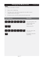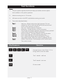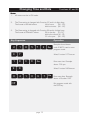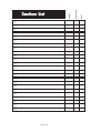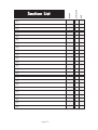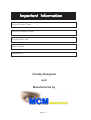
1
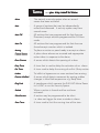
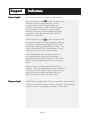
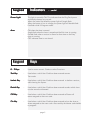
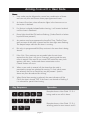
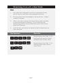
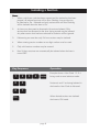
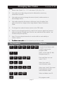
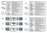
MCM Electronics
ICON I6 Series
MCM Electronics
Users Guide
MCM Electronics
Icon 16 version 6
(C) copyright MCM Electronics 2006
Contents
Contents
2
Terms you need to Know
3
Keypad Indicators
4
Keypad Keys
5
Arming an Area with a User code
6
Disarming an Area with a User Code
7
Isolating a Section
8
User Code - Programming
9
Master Code - Programming
10
Test Functions
11
Clock Functions
12
Warranty
13
Section List
14
Important Information
16
page 2
TTerms
erms
.....you may need to know
Alarm
-
The state of a security system when an armed
sensor has been activated.
Area
-
A group of sections that may be independantly
armed and disarmed. A security system may have
several areas.
Area Off
-
All sections that are programmed for that Area are
Disarmed, except sections programmed for 24 Hour
mode.
Area On
-
All sections that are programmed for that Area are
Armed except a section which is isolated.
Arming
-
To place a section or panel ready to accept an alarm.
Central Station -
A place where alarms are received and appropriate
action taken in response to the alarm.
Door Contact
-
A sensor which detects the opening of a door.
Entry Timer
-
A timer that is used to delay the activation of an alarm
Exit Timer
-
A timer used to delay the arming of an Exit /Entry section.
Isolate
-
To inhibit or bypass one or more sections from arming.
Passive InfraRed -
A sensor which detects movement by sensing sudden
changes in Infra Red temperature e.g. Body Heat
Plug Pack
-
A transformer which converts the 240 VAC Mains Power
to 16 VAC to run the Security System.
Sealed
-
When a section is Armed and has not been
activated.
Silent Section
-
A section may be programmed to be silent.
i.e. does not trigger the siren or strobe in alarm.
Siren Timer
-
A timer used to limit the running time of the siren.
page 3
K
eypad
Keypad
Section Lights
- Indicators
There are up to 48 section lights on the keypad.
-
When the Area is in the OFF mode, the sections for
that area are not armed (except for 24 hour
sections) and the Section Lights indicate the
condition of the sensor. When the Section Light is
ON, the sensor is activated e.g. door contact
detecting door open or motion detector sensing
movement. When the Section Light is OFF the
sensor is not activated.
-
When the Area is in the ON mode, the sections for
that area are armed. If the section light is Flashing
the sensor is activated and triggers the siren and
strobe light (unless programmed to be silent). This
alarm is transmitted to the Central Station. When
the light is out the section is not activated.
-
When the Area has been Armed, an exit timer
starts and holds the sections that have been
programmed for Exit delay disarmed. This allows
the user to exit the premises without activating the
alarm.
-
When the Area is armed, and the Exit timer has
finished, Entry into the premises can be made via a
section that has Entry delay. This will start the Entry
delay. If the Area is disarmed before the Entry
Delay Timer expires, there will be no alarm.
Program Light -
When fitted, this Light will be ON when a Master code is entered
and the user codes are being viewed or changed. Program Light
is also On when a user code is in Isolate or Test modes.
page 4
K
eypad
Keypad
Power Light
-
Area
-
K
eypad
Keypad
Indicators
.....cont'd
This light is normally ON. This indicates that the Plug Pack power
and backup battery are normal.
When the mains has failed the power light will single flash.
When the battery is low in voltage, the power light will double flash.
Fast flash while in Program mode.
ON when the Area is armed.
Single flash when the Area is armed and the Exit timer is running.
Double flash when a section in Alarm for that Area or the Entry
timer is running.
OFF indicates Area is not Armed.
K
eys
Keys
0-9K
eys
Keys
-
Used to enter numeric Codes or select Functions.
Test K
ey
Key
-
Used when a valid User Code has been entered to enter
Test mode.
Isolate K
ey
Key
-
Used when a valid User Code has been entered to Isolate a section,
while Arming the System.
Partial K
ey
Key
-
Used when a valid User Code has been entered to select which Area
is to be armed or disarmed
Off K
ey
Key
-
Used when a valid User Code has been entered to Disarm all
areas assigned to that user code.
On K
ey
Key
-
Used when a valid User Code has been entered to Arm the Area or
Areas assigned to that user code. Also used by the Master code holder
to program.
page 5
Arming Areas with a User Code
Notes:
1. User codes may be allocated to control any combination of Areas
and can only Arm and Disarm these preprogrammed Areas.
2.
An Area will not Arm unless all section lights in the Area are out or
the section is Isolated.
3.
If a Section is already Isolated before Arming, it will remain Isolated
until the Area is Disarmed.
4.
Power light should be ON and not flashing. (Unless Partial or Isolate
keys have been pressed.)
5.
Any section may be programmed to have Exit Time. The Exit Timer
starts as soon as the Area is Armed and the Area light starts flashing.
The beeper beeps while the Exit timer is running.
6.
Exit only via programmed Exit/Entry sections in the area that is being
Armed.
7.
If the Exit / Entry sections are not sealed when the exit timer
expires then the siren will give a 2 second warning and the entry
timer is started. If the area is not turned OFF before the entry time
expires a full siren / strobe and alarm transmission to the
Central Station will occur.
8.
When a user code is entered, all the Areas that the code is
permitted to control are selected for arming. To limit which areas
are selected, the Part or Partial key may be pressed. Specific
Areas may then be selected for Arming.
9.
When Partial Area arming is selected, the area indicators will be
ON if the Area is Armed, OFF if the Area is not Armed or flashing if
it is selected for partial Area Arming.
Key Sequence
Operation
Example shows a User Code 1 2 3 4
1
2
3
4
On
1
2
3
4
partial
being used to arm all it's Areas .
Example shows a User Code 1 2 3 4
selecting partial to arm areas 4 and 5.
4
5
On
page 6
Disarming Areas with a User Code
Notes:
1.
User codes can be allocated to control any combination of Areas
and can only Arm and Disarm these preprogrammed Areas.
2.
This key sequence also acknowledges or silences the siren / strobe if
an alarm is activated.
3.
When a user code is entered, all the areas that the code is permitted
to control are selected for disarming. To limit which areas are
selected, the partial key may be pressed then specific Areas may be
selected for Disarming.
4.
All non 24 hour sections that are isolated will be De-Isolated when an
area is disarmed.
Key Sequence
Operation
Example shows a User Code 1 2 3 4
1
2
3
4
Off
being used to dis-arm all it's Areas .
(Isolated Sections will Slow Flash)
1
2
3
4
partial
Example shows a User Code 1 2 3 4
selecting partial mode to dis-arm
areas 4 and 5.
5
Off
4
page 7
Isolating a Section
Notes:
1. When a valid user code has been entered and the isolate key has been
pressed, all isolated sections will be Slow Flashing. Any section may
be Selected or De - Selected and only sections that are Slow Flashing
will be isolated when the Area is On .
2.
An Area may be armed or disarmed with sections Isolated. Only
sections that are allocated to the Area being armed may be isolated.
Any other section that has been selected for isolation will be ignored.
3.
If disarming an area then only 24 hour sections may be isolated.
4.
When entering section numbers a two digit number must be used.
5.
Only valid section numbers may be entered.
6.
Non 24 hour sections are automatically de-isolated when the Area is
turned OFF.
Key Sequence
Operation
Example shows a User Code 1 2 3 4
1
2
0
4
0
7
3
4
isolate
being used to enter Isolation mode.
Sections 4 and 7 are being Isolated in
the Area the User Code is allocated.
When desired sections are isolated
On
the Area to ON mode.
page 8
Changing User Codes
Functions 01-80
Notes:
1. Default User Code 01 is.. 1111 with Areas 1,2,3,4,5,6, 7,8.
2.
User codes are 4 digits long and can be allocated to control any
combination of areas.
3.
User codes are used to change the status of panel, isolate sections or
acknowledge alarms.
4.
User codes cannot be the same or within one count of another User
code or be the first 4 digits of the 6 digit Master Code or Technician
Code.
5.
To change User codes all areas must be in the OFF mode.
6.
Area 9 is not a physical area but is used to limit access to panel test functions
and print requests. (Enable area 9 for the user code that will be used for test
functions and print requests.)
7.
Area 10 is not a physical area but is used to inhibit a user's abitlity to
isolate a section.
8.
To delete a user code enter the isolate key as the new code.
Key Sequence
8
Operation
2
1
5
0
1
1
2
0
1
partial
0
4
0
5
0
2
isolate
On
7
2
On
Example shows Master code
218572 used to enter
program mode.
Select a User code (01-80).
Example shows 01..
3
4
On
Enter and Store new user
code 1 2 3 4.
Select User code 01
area allocation mode.
On
Select area 4 and 5 then store.
Finish selection and exit
area allocation mode.
Select and delete user 02.
Off
Exit program mode.
page 9
Changing the Master Code
Function 00
Notes:
1. Master code default is 218572.
2.
Master code is 6 digits long.
3.
The Master code is only used to program the user codes. It cannot
change the status of the system.
4.
All Areas must be in the OFF mode to enter the master code.
Key Sequence
2
1
0
0
2
4
8
Operation
5
7
2
On
Enter existing Master code
218572 used to enter
program mode.
Select function 00
6
8
1
2
Off
On
Enter new master code
246812
Exit program mode with
the OFF key.
page 10
Test Functions
Notes:
1. Test your system regularly and this will keep you familiar with the system
and confident in the systems operation.
2.
Maximum testing time is 10 minutes.
3.
All Areas must be in the OFF mode before entering test mode.
4.
Test modes described below.
Test 1
-
Test 2
Test 3
Test 4
Test 5
Test 71
Test 70
-
Test 9
-
Walk test - Beeper and section light operates. This test
enables the user to walk around and activate sensors and
check correct operation of sensors.
Siren test - Siren sounds for 3 seconds.
Strobe test - Strobe operates unitl next key press.
Test all lights and beeper operates until the next key is pressed
used to check operation of lights and beeper.
Recall Last Alarm - last alarm flashes until next key press.
Print a report of the last 150 events in the Event log.
Print a report of the all the events in the Event log (1000).
Test mode is exited. Abort print report by pressing any key.
(Dialler Only) Sends a Test Message to the Central station.
Test mode is exited.
Key Sequence
1
2
3
Operation
4
Test
Example shows a User Code 1 2 3 4
being used to enter test mode.
1
Test 1 started - walk test
2
Test 2 started - siren test
Off
Exit test mode.
page 11
Changing Time and Date
Functions 97 and 98
Notes:
1. All areas must be in Off mode.
2.
The Time setting is changed with Function 97 and is 4 digits long.
The format is HH MM where:
HH is hours
(00 - 23),
MM is minutes (00 - 59).
3.
The Date setting is changed with Function 98 and is 6 digits long.
The format of DDMMYY where:
DD is the day (01-31),
MM is the month (01-12),
YY is the year (00 - 99).
Key Sequence
Operation
Example shows Master
2
1
9
7
1
9
9
8
0
4
8
5
7
2
On
code 218572 used to enter
program mode.
Select Function 97 Time set.
3
0
On
Enter new time. Example
shows 7:30 pm
Select Function 98 Date set.
1
0
9
Off
7
On
Enter new date. Example
shows 4 October 1997
Exit program mode with
the OFF key.
page 12
Warranty Statement
MCM Electronics Pty Ltd., the Manufacturer warrants its manufactured equipment to be free
from defects in material and workmanship for a period of sixty (60) months from the date
of manufacture as indicated by the date stamp and/or serial number on the product.
Defective units returned by the buyer at his own expense during this period will be repaired
(or replaced at the option of the Manufacturer) with an equivalent piece of re-manufactured
and tested equipment.
The repaired or replaced equipment is then warranted for the balance of the initial warranty
period or for thirty (30) days, whichever is longer.
The repair or replacement will be without charge provided that the equipment has not been
subjected to electrical or physical misuse or to unauthorised repair or modification.
The foregoing warranty is in lieu of all other warranties, express or implied, including, but
not limited to, merchantability or fitness for a particular purpose.
The purchaser's exclusive remedy with respect to any and all losses or damages resulting from
any cause whatsoever, shall be repair or replacement as specified above.
The Manufacturer shall in no event be liable for any consequential or incidental damages,
however occasioned, whether by negligence or otherwise.
No suit or action shall be brought against the Manufacturer more than one (1) year after the
accrual of the cause of action therefore.
No agent, employee or representative of the Manufacturer nor any other person is
authorised to modify this warranty in any respect. This warranty gives you specific legal rights
and you may also have other rights which vary from state to state.
page 13
3
4
5
6
7
8
9
10
11
12
13
14
15
16
17
18
19
20
21
22
23
24
page 14
24HR
2
ENTRY/EXIT
1
AREAS
Section List
27
28
29
30
31
32
33
34
35
36
37
38
39
40
41
42
43
44
45
46
47
48
page 15
24HR
26
ENTRY/EXIT
25
AREAS
Section List
Important Information
Central Station Phone
:
Security Company Phone
:
Control Panel Type
:
Date Installed
:
Installed by
:
Proudly Designed
and
Manufactured by
page 16