1
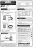
Rolling Door Operator User’s Manual MODEL: RSI-500KG Rolling Steel Ind. Brooklyn NY Tel. 718 272-4444 500KG ROLLING DOOR OPERATOR OUTLINE 1. Important safety information……………………………………1 2. Main technical parameters………………………………………1 3. Introduction ………………………………………………………1 4. Installation and adjustment ……………………………………2 5. Electrical……………………………………………………………5 6. Maintenance ………………………………………………………8 7. Service help ………………………………………………………8 1. Important safety information Carefully read and follow all safety precaution and warnings before attempting to install and use rolling door operator, incorrect installation can lead to severe injury. The rolling door operator should be installed by a qualified technician; otherwise, serious 1 500KG ROLLING DOOR OPERATOR personal injury or property damage may occur. Notify the users that the door operator is never to be operated unless it is in full view. Keep remote controls away from children, to prevent the door from being activated involuntarily. Before any job on the door operator, cut out electrical power. DO NOT in any way modify the components of the rolling door operator, otherwise serious personal injury or property damage may occur. We do not accept responsibility for damage or injury resulting from installing this door operator. When opening or closing the door, do not attempt to walk or drive through the door. The rolling door operator must be grounded. Do not pull the hand chain or release lever during opening or closing the door. Do not close the door by pulling the release lever as normal working mode, otherwise, serious personal injury or property damage may occur. (It’s only an emergency mode) To protect the door from crash, engage the release lever quickly while the door is going to reach the closed position, then pull the release lever again to close the door lightly. Regularly check the rolling door operator. If you have any problem, please contact our sales agent. Our company reserves the right to change the design and specification without prior notification. 2. Main technical parameters Power supply 110×(1±10%)V, 60Hz Motor speed 1680 r/m Rated power 370W Rated current 4A Max. lift capacity 500kg Roller diameter 127mm Transmitting ratio 210:1 Continuous working time 5 minutes Environment temperature -20ºC to +45ºC Weight of main unit 12kg 3. Introduction Main features Compact design, attractive appearance, safe and reliable performance. It has the advantages of light weight, low noise, convenient to install, safe and reliable performance. Manual operation in case of power failure. 2 500KG ROLLING DOOR OPERATOR Main structure (see Fig.1) Adjustable screw for roller chain Limit switch Motor Screw Pawl Connector Cover Chain Release lever Fig.1 4. Installation and adjustment Right hand and left hand installation You may install the rolling door operator to left or right side. Operator is normally delivered right hand. (View from inside the opening), If you need to change it to the left processed as follows: undo the four screws on the housing, then turn the upper housing 180° and ensure the chain hangs vertically, turn the pawl 180° at the same time, finally tighten the screws. Make sure there is no clearance between upper housing and lower housing. There is no clearance here. turn the pawl 180 at the same time. Turn the uppper housing 180¡ ã Loose the four screws Fig.2 Install the rolling door operator to right side. Right side sprocket bracket Install the sprocket bracket on the wall or wall bracket horizontally, if the distance is not sufficient the bracket angle may need to be adjusted (The installation angle can be adjusted to between 0° and 45°, ensure the chain hangs vertically. See Fig.3) 3 500KG ROLLING DOOR OPERATOR Sprocket bracket The installation angle can be adjusted to between 0¡ãand 45¡ã , ensure the chain hangs vertically. Fig. 3 Left side square plate Lock the bearing in bracket with screws. Fix the square plate on the wall or wall bracket. Bear ing Bearing Square plate Bearing bracket Fig.4 Roller installation Install the roller as shown in Fig.5. Square Bearing Circular plate bracket Bearing Cylindrical pin plate I Roller Circular plate II Solder circular plate I I to the roller. Solder two pieces of circular plates I and cylindrical pin to the roller. Fig.5 4 Bigger sprocket Sprocket bracket 500KG ROLLING DOOR OPERATOR Door operator Fix the door operator to the sprocket bracket. Make sure that the nuts securely tightened and chain hangs vertically. Adjust the screw to tighten the roll chain see Fig.1. Fig.6 Limit switch Limit switches are needed to stop the door at the correct opened and closed positions. Loose the screw, manually open the door to desired position, turn the limit cam wheel until OPEN limit switch clicks, finally tighten the screw. Loose the screw, manually close the door to desired position, turn the limit cam wheel until CLOSE limit switch clicks, finally tighten the screw. After adjusting, you can open the door then close the door and observe whether the door has successfully reached the opened and closed positions. If the door does not reach the opened or closed position, fine adjust the limit cam wheel to suit the desired distance. The process is the same as the adjusting as above. Chain In case of power failure, you can open or close the door manually by pulling the hand chain. It is important to ensure that the chain is not fitted twisted. If the chain is twisted, malfunctions may occur when the hand chain is used. Please do not pull the chain during closing or opening the door, otherwise, serious personal injury or property damage may occur. Release lever In case of power failure, pull the release lever to disengage the door quickly. WARNING: When pulling the release lever to disengage the door, do not attempt to walk or drive through the door. Otherwise, serious personal injury or property damage may occur. Brake When the operator has been in use for some time, brake block wears off and can not stop the door well, adjusting the brake block could become necessary. Adjust the brake block can be done by adding spacers. Loose the four screws on the housing, undo the round nut (M8) and brake block, add spacers according to your requirement, ensure the clearance between the brake block and sprocket is 0.6 mm -1mm, then assemble the brake block and nut. 5 500KG ROLLING DOOR OPERATOR OUT X8 G H Pink X7 +24V S X10 J Purple Power output: AC24V 5. Electrical Installation Make sure that power is OFF before making any electrical connections. Fix the control box on the wall and perform the wiring. ’ (terminal X2). Connect power wires (AC110V) to ‘L’, ‘N’ and ‘ Connect capacitor wires to ‘B’ (See terminal X1) and ‘A’ (terminal X2). Wiring between control box and rolling door operator (see Fig.7) Connect Brake solenoid wires to ‘E’ and ‘F’ (terminal X1). Connect motor wires to ‘C’, ‘D’, ‘A’ and ‘N’. (Terminal X1 and terminal X2). ’(terminal X2). Connect earth wire to ‘ Connect limit switch wires to terminal block X10. Notice: these wires have been connected before delivery. All you need to do is connect the connector comes from the rolling door operator to the control box. Green Q X6 X5 Receiver or external button switch Stop Close Open N.C. N.O. N.O. X4 Blue Capacitor Blue B Red E Red F Orange C Black D S S 0V 0V R DG IR IC K G T IC card X1 +5V S K G T X2 L A N Yellow Yellow and green Connector Orange Black Yellow White Yellow and green Red Red Purple Green Pink Power Cable (AC110V) Motor Earth CL OP COM Limit switch N.C. Electromagnet Fig.7 Gate Operator 6 N White +5V 0V Open Close Stop N.O. N.O. N.C. Control box button X3 Photocell N.O. Loop Keypad detector 500KG ROLLING DOOR OPERATOR Fig.8 DIP-switch (IC2) Press ‘UP’ button, but door runs in wrong direction, slide the first DIP-switch to opposite side. Set the second DIP-switch to ON position, the door inching moving. 7 500KG ROLLING DOOR OPERATOR Connecting optional safety device Note: make sure the control box power switch is OFF before connecting safety device wiring to the terminal blocks. Loop detector (N.O.) Connect the power wires of loop detector to terminal block X7, connect the signal wires to terminal block X6 and X5. See Fig.9 C o n tro l b o a rd te rm in a l b lo c k X6 X7 S Q S +24V S X5 DG R IR IC + 2 4 V G n d S ig n a l L o o p d e te c to r Fig.9 Photocell (N.O.) Connect the power wires of photocell transmitter to terminal block X7, connect the power wires of photocell receiver to terminal block X7 and signal wires to terminal block X6 and X5. See Fig.10 C o n tro l b oa rd term in a l block X6 X7 + 2 4V Q S S G nd + 2 4V P ho to ce ll tra n sm itter X5 R S DG IR IC + 24 V G n d S ig na l P h o tocell re ce iver Fig.10 External button switch (three button mode) / Receiver Connect external button switch or receiver to ‘K’ (open), ‘G’ (close), ‘T’ (stop) of terminal block X4, connect common wire to ‘S’ of terminal X6. Notice: the device can be controlled by a transmitter after the remote receiver is connected. Control board terminal block X6 X4 S S com K R Open Close G T Stop Receiver or external button switch Fig.11 8 500KG ROLLING DOOR OPERATOR Keypad (single button mode) Connect signal wire of keypad to ‘R’ (terminal block X6), connect common wire of keypad to ‘S’ (terminal block X6). C o n tro l b o a rd te rm in a l b lo c k X6 S S R Com s ig n a l K eypad Fig.12 Adjustment If the photocell beam is interrupted, the door will reverse and go open during closing. If not, exchange the motor wires (i.e. exchange the black wire and orange wire). See Fig.7 terminal block X1. 6.Maintenance Check the door once a month. The door must be in good working order. Regularly check the limit switch. Regularly lubricate the chain. For service, call an experienced technician. The control box should be installed in cool, dry and ventilated places, kept away from sunlight and rain. Periodically test the safety device to make sure they are functioning correctly, if they are not, replace immediately. Keep the operator and control box clean at all times. Our company reserves the right to change the design and specification without prior notification. 7. Service help Following this guide may resolve your service problem. If you have any problem, please contact our sales agent. Motor does not work: Check the motor. Check the limit switch. Check the capacitor, rectifier and relay. Fuse blown: Check the motor. Check the relay and brake solenoid. Fail to open or close the door by chain: The chain may be jammed. Fasten the brake solenoid. Brake fails to work: Check and replace the pawl. Clean the oil on the brake block. Replace the spring in the brake solenoid. 9 500KG ROLLING DOOR OPERATOR Rolling Steel Ind. Brooklyn NY Tel. 718 272-4444