1
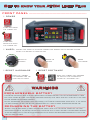
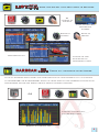
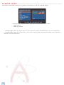
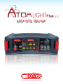
User’s Guide
www.roverinstruments.com
Plus
Get to know your ATOM Light Plus
FRONT PANEL _______________________________________________________
• POWER
TURN ON press
the ‘HOME’ key.
TURN OFF
press and hold
the ‘HOME’ key
• WHEEL
Rotate the wheel to navigate across the screen and to change values.
Push it to select an icon or item
Rotate to
Navigate
• RESET HARDWARE
Keep the “HOME”
key pressed for 10”
and turn on again
Press
and HOLD
Press to
Select
• RESET SOF T WARE
+
Keep the “HOME” key pressed
to turn on and immediately
after the “VOLUME” key
WARNINGS
RECHARGEABLE BAT TERY _______________________________
This device contains a built-in Ni-MH (Nickel-Metal Hydride) battery that can be recharged a large
but finite number of times. The battery contains chemicals that might wear with time even if not used.
Please dispose of batteries properly.
Do not disassemble the battery pack nor expose it to extreme temperatures (over 50°C). If the device
has been exposed to very low or high temperatures let it rest at room temperature before use.
RECHARGING THE BAT TERY _____________________________
Battery must be recharged at room temperature (about 25°C) with the device turned off. To avoid
premature failure of the battery never leave the device with an empty battery for prolonged periods.
Ni-MH batteries have a high self-discahrging rate and should be recharged periodically even if not
used to avoid failures.
2
HOME SCREEN ______________________________________________________
Press the ‘HOME’ key to get to the home screen, rotate the wheel to navigate either to the
‘SAT’, ‘TV’ or ‘CATV’ icon then press the wheel to select the desired measurement mode
Press the ‘HOME’ key at any time to get back to the home screen
SCREEN NAVIGATION ___________________________________________
Use the wheel to navigate across the screen and to change values
• DISPL AY ZONES
Tuning parameters
Live picture
Measurements
Channel info
Transport Stream info
Context sensitive menu
• CHANGING VALUES
Navigate to an item then select
Rotate the wheel to change the value of the item
• DROP-DOWN MENUS
Navigate to a drop-down menu item then press and hold
Rotate the wheel to highlight a value then press to select
• ENTERING NUMBERS
Navigate to a numerical value then press and hold
Press the keys showing the desired values to enter numbers
3
SAT
SAT
Analyze Satellite Television Signals
SWITCH TO SAT MODE _________________________________________
o
r
A
N
D
SAT
P
R
E
S
S
SAT channel plan
"Satellite information (mux data)
is provided in cooperation with
LyngSat www.lyngsat.com”
SAT MEASUREMENT SCREENS ____________________________
Main measurements & live picture
Navigate to live picture zone and Press
the wheel to zoom. Press again to return
to the measurement
Constellation screen
Navigate to “ZOOM” and select
the constellation square window
to enlarge
press to cycle through
SAT measurement screens
REL ATED FUNCTIONS ________________________________________
SAT Spectrum
Analyzer
4
SAT Channel
Plan
Selection
MPEG SERVICE MPEG
service
list
TV
TV
Analyze Terrestrial Television & Radio Signals
SWITCH TO T V MODE ____________________________________________
o
r
A
N
D
TV
P
R
E
S
S
TV channel plan
DIGITAL T V MEASUREMENT SCREENS _______________
Main measurements & live picture
Constellation screen
Navigate to “ZOOM” and the
constellation square window
to enlarge
Impulse response screen (echo)
press to cycle through
TV measurement screens
5
ECHO MEASUREMENT __________________________________________
Navigate to “TYPE”
and select the echo visualization mode:
DISTANCE oR TIME
excellent reception
No ECHO present. the GREEN window
represents the guard interval obtained from
the reception parameters (TPS) of the tuned
digital channel.
good reception
1 ECHO present but inside the guard
interval, coming from a distance of
25 Km, equal to a 83,0 µs delay.
POOR reception (or IMPOSSIBLE),
DESTRUCTIVE INTERFERENCE.
1 ECHO present but outside the guard interval,
coming from a distance of 40 Km,
equal to a 133,0 µs delay.
REL ATED FUNCTIONS ________________________________________
TV Spectrum
Analyzer
6
TV Channel
Plan
Selection
Barscan
(tilt graph)
MPEG SERVICE MPEG
service
list
CATV
CATV
Analyze Cable Television Signals
SWITCH TO CAT V MODE _______________________________________
o
r
A
N
D
CATV
P
R
E
S
S
CATV channel plan
CAT V MEASUREMENT SCREENS _________________________
Main measurements & live picture
Navigate to live picture zone and
Press the wheel to zoom. select
again to return to the measurements
Constellation screen
Navigate to “ZOOM” and
select the constellation
square to enlarge
press to cycle through
CATV measurement screens
REL ATED FUNCTIONS _________________________________________
CATV
Spectrum
Analyzer
CATV Channel
Plan Selection
Barscan
(tilt graph)
MPEG SERVICE
MPEG
service
list
7
SPECT
SPECT
Spectrum Analyzer
SWITCH TO SPECT MODE _____________________________________
OR
SPECT
SPECTRUM ANALYZER SCREENS _______________________
Navigate to SPAN to modify the value or
directly select the active span value
or
Fast spectrum
Rotate to
navigate
Enter to
confirm
Fast spectrum with peak memory
press to cycle through
spectrum analyzer screens
REL ATED FUNCTIONS ________________________________________
HELP (inspect an unknown signal)
8
MPEG SERVICE
(MPEG
LIST
service) show and select available mpeg ts services
MPEG SERVICE
Or
navigate to
Vpid-Apid
in the TV-CATV-SAT
measurement
windows
Rotate to
navigate
Mpeg service list
BARSCAN
Enter to
confirm
navigate to VpidApid return to
measurement mode
TILT
BARSCANGRAPH
Check all channels level/power
In the TV standard canalization the meter displays the level/power of all TV channels.
In AUTOMEMORY or MANUMEMORY PLAN the meter displays the memorized channels and
distinguishes Analog and Digital signals using 2 different colours
OR
BARSCAN
Function available only
in TV or CATV mode
Barscan (tilt graph) view
9
HELP
Inspect an unknown signal
Change “MRK. FR” value in spectrum
mode to select an unknown carrier
Help tries to discover carrier’s
parameters
Press the ‘HOME’ key to get back to the home screen then use the wheel to select either
‘SAT’, ‘TV’ or ‘CATV’ mode & press again to view carrier’s measurements and picture
SPECIAL
SPECIAL FUNCTIONS
SPECIAL
the special functions depend on
the active operating mode:
TV SAT or CATV
T V: Buzzer & Noise Margin graphic ____________________
Navigate on:
BUZZ&NOIS.MARG.GR
10
Buzzer & Graphic of the progress of the noise
NOISE MARGIN of the tuned channel according to time.
high tones = the BEST Noise Margin level
deep tones = the WORST noise margin level
Noise Marg = real time noise margin
Max n.marg = maximum stored noise margin
SAT: SAT SCR ________________________________________________________
WARNING:
to use the SCR function, you must first
disactivate the DiSEqC tone (off).
Select in sequence “DIS” and “OFF”
in the sat measurement window
Navigate on: SAT SCR
Navigate on “LNB TYPE” and select the
model of the installed LNB/multiswitch.
Navigate on “SCR USER” and select the
number of users to test (user 1-8).
Navigate on “SCR CABLE TEST” to check,
in spectrum mode, the 8 output frequencies
(user 1-8) of the LNB/multiswitch.
Press “SPECT” to visualize the spectrum
or “SAT” to carry out measurements.
SAT: SAT Finder ____________________________________________________
Navigate on: SAT FINDER
if the selected satellite is correct the buzzer
will sound, alternatively look for the correct
satellite. Optimize the satellite dish pointing
and the polarization skew to obtain the maximum
NsMAR (noise margin) value
11
MEMORY
MEMORY
Work with Plan and Log Files
MEMORY
AUTOMEMORY ( T V ) _______________________________________________
To automatically store all the existing channels in a city or building
Set the desired parameters:
Navigate to “to FILE N” and select the destination file “AUTO” where the search must be saved.
Navigate to “LEVEL” and set the minimum level threshold of the analog channels searched.
Navigate to “POWER” and set the minimum power level of the digital channels searched.
Navigate to “DISCOVERY” and set the channel search mode.
- TERR ONLY (terrestrial only)
- TERR & CABLE (terrestrial & cable)
Navigate to “START SAVE” to create a new channel plan and to activate the search.
NB: If the words “START OVERWRITE” appear, the selected file will be overwritten.
upon automemory completion the new
plan is automatically selected
wait a few mins, the meter indicates the recorded ANALOG & DIGITAL CHannels
12
LOGGER _________________________________________________________________
Set the desired parameters and select
“save?” to create a new log file
Set the parameters to select the new log
file and select “RECALL” to show it
Rotate to
Navigate
Browse through measurements
saved in the log file
S.M.A.R.T. PROGRAM
The S.M.A.R.T. is required to interface the meter with the PC,
Using the PRO version of the S.M.A.R.T. program is it possible to control the internal
memories (MANU FILE, automemory, logger) for example, create or adjust the memory
plans, print them or export them in excel®.
EXCEL is a trade mark of Microsoft corporation.
13
Volume & Configuration
menu for display configuration and
other important settings
BAT TERY SAVING __________________________________________________
to set the battery save feature.
In ON mode, if no key is pressed, after 30 seconds, the
display brightness is reduced (only for ATOM LIGHT PLUS
and ATOM POWER models) and after 5 minutes the meter
automatically turns off. press any key to temporarily
reset the battery save mode.
14
C/N T YPE _______________________________________________________________
Set the measurement mode of the carrier noise ratio “C/N” (in band-out band)
Navigate on ‘configuration menu’
from the volume screen
Navigate on TV then C/N TYPE
C/N measurement mode “IN BAND” the
signal/noise ratio is measured between
the signal level of the video carrier
(signal/carrier, red marker) and the
noise level, estimated in the band
between the colored subcarrier and the
audio carrier (white marker)
C/N measurement mode “outside the band”
The signal/noise ratio is measured between
the signal level of the video carrier
(signal/carrier, red marker) and the noise
level estimated in the guard band (-1.250
MHz from the video carrier, white marker)
15
DISCOVERY ____________________________________________________________
Identifies the modulation of a tuned TV channel in the TV master PLAN
Navigate on “DISCOVERY” and set the identification mode:
- TERR ONLY
- TERR & CABLE
- DISCOVERY mode is active only if the antenna cable is connected to the instrument
- DISCOVERY mode is not active if you use a manual or automatic memory plan (Manual
Memory or Automemory)
16
- NOTES -
17
To: ROVER INSTRUMENTS SERVICE DEPARTMENT
Fax: +39 030 990 6894
or e-mail: [email protected]
Subject: FAULT Identification Form
�
FAULT IDENTIFICATION FORM
PLEASE FILL ALL THE SQUARED AREAS.
Date:.............................................................................................................................
CUSTOMER INFORMATION.
•
•
•
•
•
•
Name or Company Information:......................................................................................
Address:....................................................................................................................
Tel.:...........................................................................................................................
Fax:...........................................................................................................................
E-mail:.......................................................................................................................
Skype:.......................................................................................................................
METER INFORMATION.
•
•
•
•
•
•
•
Meter Model:..............................................................................................................
Purchase date:. ...........................................................................................................
Invoice number:...........................................................................................................
Bought from:..............................................................................................................
Firmware version:........................................................................................................
Hardware version:.......................................................................................................
Serial number:............................................................................................................
FAULT DESCRIPTION.
In few but precise words please describe here below (*) the fault found and forward to our Service
Department for more instruction on how to proceed. If necessary provide picture or logger & saved
screen using the SMART PC interface sortware (available on our website www.roverinstruments.
com).
..........................................................................................................................................................
..........................................................................................................................................................
..........................................................................................................................................................
..........................................................................................................................................................
..........................................................................................................................................................
..........................................................................................................................................................
..........................................................................................................................................................
..........................................................................................................................................................
..........................................................................................................................................................
(*) add lines if more space is needed for your description.
�
DO NOT SEND BACK THE METER WITHOUT OUR AUTHORIZATION
NUMBER AND ROVER SHIPMENT INSTRUCTIONS OTHERWISE THE
METER WILL BE REJECTED UPON ARRIVAL TO ROVER.
For receive the authorization number call: +39 030 9198 299
18
SERVICE NOTES and GUARANTEE REGULATIONS
(CEE and EXTRA CEE)
ROVER Laboratories. S.p.A. has a standard guarante period of 12 months.
This is extended to 24 months for countries within the European Community, and in any case, in
accordance with the laws and/or possible regulations applied in your country.
GUARANTEE REGULATIONS:
1. IMPORTANT: the guarantee is valid only upon the presentation of invoice or receipt to Rover
Laboratories S.p.A.. The date of purchase must be clearly indicated on the invoice/receipt
2. The guarantee covers the free of charge replacement of the only parts, which malfunctioning
is solely due to manufacturing faults. The faults must be individuated and defined by Rover
personnel only.
3. The guarantee is void if:
a. the equipment is tampered with or repaired by non-authorized personnel
b. damage is found, caused by the incorrect use of the equipment, without following the advice explained in the User’s Guide accompanying the equipment.
c. damage is found caused by the use of the equipment in unsuitable working environments.
4. The following parts are not covered by the guarantee:
a. Parts subject to wear, such as aesthetic ones, keyboard, plastic chassis, ...
b. Batteries.
c. Bags and carrying cases, included shoulder straps.
5. The equipment can not be replaced and the guarantee extended after the repair of a fault..
SERVICE NOTES AND PROCEDURES:
6. The equipment can only be repaired by the manufacturer or by an authorized Rover
Laboratories service center:
a. Before returning the meter for repair, always contact the distributor where you purchased
the unit or an authorized service center if present in your area to obtain the return
procedure for your analyzer. If no authorised ROVER service centers are available in your
area, please contact Rover Laboratories S.p.A. directly at the following telephone/fax
numbers and/or e-mail address:
• +39 030 9198 299 Telephone number
• +39 030 990 6894 Fax number
• [email protected]
b. Important: please take note that non-authorised returns for repair to Rover Laboratories
S.p.A. will be rejected.
c. When returning the meter, always send it with the following documentation attached:
• the fully-compiled FAULT IDENTIFICATION FORM
• transport document
• the eventual request for an estimate of repair costs
d. Please note that the request for an estimate of repair costs must be submitted upon
return of the analyzer with a written note. If the repair cost estimate is not accepted, Rover
Laboratories reserves the right to charge the customer for the estimate costs analysis.
19
7. Risks and costs for transport to Rover Laboratories S.p.A. must be sustained by the buyer.
After repair, if the equipment is under guarantee, Rover Laboratories S.p.A. will pay for the
transport returning the goods to the customer. If the instrument is not under guarantee, after
repair, the equipment will be returned by courier service with the amount to be paid by the
customer shown on the invoice.
8. The guarantee does not cover compensation for direct or indirect damages of any kind to
people or goods caused by the use of the equipment and/or compensation caused by the
suspension of use due to eventual repairs.
9. Rover Laboratories. S.p.A. is not responsible for eventual tampering and/or modifications
that may cause the goods to no longer adhere to the European “CE” regulations, especially
regarding EMC and safety.
10.Rover Laboratories instruments is recognised and is fully compliant with DVB regulations
and specifications (ETS 300 421–12/94) and is consequently marked with the DVB logo and
registered with id. N. 3088.
DISPOSAL of ELECTRONIC EQUIPMENT
Disposal of electric / electronic equipment (applicable in all CEE countries and whereever separate
waste collection system is applied).
This symbol on the packaging indicates that the product should not be considered as domestic
waste. The product, at the moment of disposal, should be brought to a waste collection point with
the proper facilities to manage electrical/electronic appliances.
Electric/electronical appliances, if not disposed of correctly, may have negative
consequences on your health and enivironment.
Furthermore, a proper recycling procedure helps mantaining natural
resources.
To have more information about proper disposal of this product, please refer
to your local waste management offices or the shop where this product was
bought.
20
MAINTAINING the METER
CLEANING THE METER
Cleaning the meter from dust and dirt is easy and helps mantaining it in optimal work conditions
through the years. The cleaning procedure is simple and quick and requires only minor attention.
Never use chemical aggressive products (diluent) and/or abrasive or rough clothes which may
damage plastics and displays.
Always use a soft cloth, damped with a simple water and alcohol solution or a de-greasing not
abrasive liquid soap.
Keyboard and display should be gently cleaned. Rubbing the keyboard and/or the display(s) may
seriously damage their functions.
MANTEINANCE AND CARE OF THE METER
This meter has been designed to withstand severe conditions of use. Even so, its life may be
prolonged by respecting some simple and effective rules:
• The meter has not been designed to withstand high temperatures (over 60°C or 140° F).
Those temperatures can be easily reached when the meter is left in a car, especially behind the
windshield, or in the trunk. The LCD display and/or other details may easily be damaged by the
extreme temperature.
• The internal battery may rapidly loose its efficiency if exposed to high or low temperatures. This
will result in reduced autonomy of the meter when powered by internal battery.
• When recharging the internal battery, do allow a good air circulation around the meter and
the adapter: do not cover it with clothes and do not recharge the battery when the meter is
contained in its transport case
• The meter is not waterproof, even if it is protected against incidental water drops. In case of
contact with water, electronic circuits may be damaged, allow the meter to dry thoroughly before
trying to turn it on. Do not use hairdryer or other strong heating sources, but just leave the
meter in quiet air. If possible, contact Rover Laboratories S.p.A. Technical Assistance.
21
SERVICE and SUPPORT
WEB REGISTRATION and SOFTWARE UPGRADES
Service and Support Registration
• Enter Rover’s website www.roverinstruments.com
and make a language selection.
• In the main page select Service and Support
- Sw updates.
• Click on Registration at the top of the web page.
• A form will be displayed and all the relevant data
must be typed including a User Name of your
choice.
• SEND the form.
• Once the form has been sent you will receive an e-mail from Rover to activate the registration,
in this e-mail click the relevant link to receive a second e-mail with the confirmation of your
User ID and a Rover assigned password.
• Please take note of your User Id and Password because they are required to enter the
firmware upgrades section.
(If you already have a User ID and Password to enter the Service & Support area, you do not
need to follow this procedure).
Software Upgrades
Once you enter the Service & Support area with your User ID and Password, you can download all
the available files to update your measuring instrument:
S.M.A.R.T
Your meter’s software can be upgraded from the Rover website by downloading the free PC
S.M.A.R.T. program.
The Smart program is necessary to interface the measuring instrument with your PC, to update
the firmware or memory of your measuring instrument.
A full set of instructions can be downloaded from the Service Section.
The Smart program has two versions: standard and Pro. After 30 days of use the Smart
program becomes standard. To permanently enable the Pro version you need a license. Contact
your distributor for details.
The Smart program always allows you to upgrade your meter’s firmware. The Pro version is
required only for memory handling (memory plan editing).
Free Firmware upgrade
The latest firmware upgrade for your meter can be found in the Service & Support area.
Find your meter model and download the relevant firmware file.
You must use the Smart program to upgrade your firmware: in the Smart section of the Service
& Support page (top of the page) you will find the firmware upgrade procedure.
Free MEM files upgrade
If available, the latest MEM file upgrade for your meter can be found in the Service & Support
area.
Find your meter model and download the relevant MEM file (if available).
You must use the Smart program to upload the MEM file to your meter: in the Smart section of
the Service & Support page (top of the page) you will find the MEM file upload procedure.
To upload a MEM file to your meter, the Smart Pro version is required.
22
PROCEDURE TO UPGRADE FIRMWARE
IN A MEASURING INSTRUMENT
N.B. The S.M.A.R.T. program is required to upgrade firmware
•
•
•
•
•
•
•
•
•
Connect the instrument to the mains and turn it on.
Connect the USB cable FIRST to the meter and THEN to the PC.
Start the SMART Program.
Click “Instrument” and then “Upgrade Firmware” In the SMART program menu.
In the “Open” window, select the file to be used for up-grades and confirm the selection by
pressing the “Open” key.
The “Upgrade Firmware” window will then open, where you can select the instrument
model.
Press “Upgrade” to start the up-grade.
When the up-grade has been completed correctly, the PC will show the message “Program
Successful” and a brief summary of the instrument settings.
Turn the instrument on and check the number of the new firmware version in the start-up
window or the Self-Test.
WARNING!
• Do not switch-off, use or disconnect the Meter from the mains during the up-grade.
• If the up-grade procedure is not successful:
- Check connections and repeat the operation
- If the operation described in this paragraph continues to fail, contact Rover Instruments
([email protected]).
MEM FILES UPLOAD PROCEDURE
N.B. The PRO version of the S.M.A.R.T. program is required to load a MEM file in your
meter
•
•
•
•
Connect the instrument to the mains and turn it on.
Connect the USB cable FIRST to the meter and THEN to the PC.
Start the SMART program.
Click “Instrument” and then “Connect Instrument” in the SMART program menu.
A window will open where you can select your meter model and START the connection.
• Click “TOOLS” and then “MEM” and “OPEN MEM” in the SMART program menu.
• Select the “MEM” file downloaded from the Rover’s Service web site.
• Click “Instrument” and then “MEM” and “WRITE MEM TO INSTRUMENT” in the SMART
program menu. The SMART program will upload the new MEM file to your meter.
For more information about the SMART program, read the relative user guide,
which can be downloaded from the Service and Support area.
23
BATTERIES
IMPORTANT:
- ALWAYS TURN THE INSTRUMENT OFF BEFORE CONNECTING THE BATTERY CHARGER.
- DO NOT LEAVE THE BATTERIES DISCHARGED FOR LONG PERIODS.
- ALWAYS CHARGE THE BATTERIES AT NIGHT FOR AT LEAST 8-10 HOURS, EVEN IF THEY ARE NOT COMPLETELY DISCHARGED.
USEFUL INFORMATION:
1. The batteries supplied are high quality, tested individually, to guarantee an autonomy of
between 3 hours MIN and 4 hours MAX depending on the following conditions:
– the use of the “AUTO OFF” function, that automatically turns off the meter after 5 minutes of inactivity (saving up to 30%).
– the LNB power consumption: Single, Dual or Quadruple
– the external temperature: with temperatures of less than 10°C, 20% of the capacity is lost,
– the age of the batteries: a 10% loss in efficiency each year,
– May we remind you that with dual DISPLAY meters, if you turn off the colour TFT DISPLAY and only use the BW graphics display, battery duration will double.
2. The battery indicator has a +/- 20% tolerance (like all battery powered electronic
devices) according to the following factors:
– the battery’s charging percentage
– external temperature & battery wear and tear status.
24
- NOTES -
25
- NOTES -
26
INDEX
2 – Get to know your ATOM LIGHT Plus
SAT
4 – SAT: analyze Satellite Television Signals
TV
5 – TV: analyze Terrestrial Television & Radio Signals
CATV
7 – CATV: Analyze Cable Television Signals
SPECT
8 – SPECT: Spectrum Analyzer
MPEG SERVICE
9 – LIST: show and select available mpeg ts services
BARSCAN
9 – BARSCAN: Check all channels level/power
10 – HELP: Inspect an unknown signal
10
SPECIAL
–
SPECIAL FUNCTIONS
MEMORY
12 – MEMORY: Work with Plan and Log Files
13 – S.M.A.R.T. PROGRAM
14 – Volume & Configuration
18 – FAULT IDENTIFICATION FORM
19 –– SERVICE NOTES and GUARANTEE REGULATIONS
20 – DISPOSAL of ELECTRONIC EQUIPMENT
21 – MAINTAINING the METER
22 – SERVICE & Support WEB Registration and SW Upgrades
23 – PROCEDURE to UPGRADE FW
23 – MEM FILES UPLOAD Procedure
24– BATTERIES
27
Customer Support
[email protected]
+39 030 9198 299
skype ® call name
wecare.roverinstruments
UG-ATOMLIGHTPLUS-STC-EN-V6
Designed in Europe, Assembled in Europe
RO.VE.R. LABORATORIES S.p.A. Via Parini 2, 25019 Sirmione (BS) Italy tel. +39 030 9198 1 fax +39 030 990 6894
product specification are subject to change without notice . All trademarks used are properties of their respective owners.