1
HM Plus SS
User's Guide
2014
HM Plus SS User's Guide
Table of Contents
The HM Plus SS ...........................................................................................................................2
How Strain-Gauge Quickshifters Compare to Other Quickshifters .........................................3
Conventional Quickshifters vs. Strain-Gauge Quickshifters .............................................4
Strain-Gauge Quickshifters vs. Load-Cell Quickshifters ...................................................5
HM Seamless Shift Technology (HMSS) ................................................................................6
Features at a Glance ..............................................................................................................6
Installation ...............................................................................................................................7
Installing the Sensor .........................................................................................................8
Installing the LCD Control Box .........................................................................................9
Connecting to the Electrical System.................................................................................9
Setup .....................................................................................................................................10
Compression / Extension ................................................................................................11
Sensitivity ........................................................................................................................12
Kill Time...........................................................................................................................12
HMSS On / Off ................................................................................................................13
Calibration .............................................................................................................................13
Stationary Test ......................................................................................................................14
Operation ...............................................................................................................................14
Frequently Asked Questions .................................................................................................14
Specifications ........................................................................................................................16
As with any new technology, you must read and follow all set-up and usage instructions in the applicable
user guide enclosed or provided electronically. If you fail to do so, this product may not function properly
and you may not get results advertised.
While HM Quickshifter has made every effort at the time of publication to ensure the accuracy of the
information provided herein, such information is subject to change without notice.
Table of Contents -- Page 2 of 17
Copyright © 2014 HM Quickshifter UK, Ltd.
HM Plus SS User's Guide
The HM Plus SS
Introducing the Next Generation in Quick Shifting
Congratulations on your purchase of an HM Plus SS. HM Quickshifters are the only strain-gauge
quickshifters outside the MotoGP paddock!
For many years the design team at the world renowned HM Quickshifter Labs have been working on the
next generation of quickshifter aimed at customers who want (and/or need) to squeeze the very best in
power and efficiency out of their motorcycles.
Because the existing HM Quickshifter has the reputation for being the world's best and most reliable straingauge-based quickshifter, improving on the existing HM Quickshifter has been a tough job. We are now
very proud to unveil...
The HM Plus SS.
Copyright © 2014 HM Quickshifter UK, Ltd.
How Strain-Gauge Quickshifters Compare to Other
Quickshifters -- Page 3 of 17
HM Plus SS User's Guide
How Strain-Gauge Quickshifters Compare to Other Quickshifters
As most readers will know, a quickshifter works by killing the ignition for a certain period of time in order to
relieve stress on the gearbox, thus allowing the pressure on the gear lever to slip the transmission into the
next gear without missing a gear, grinding or chipping gear teeth or engagement dogs.
However, something that is less well understood is how different quickshifter technologies compare to one
another in the marketplace in terms of advantages and disadvantages.
Conventional Quickshifters vs. Strain-Gauge Quickshifters
CONVENTIONAL QUICKSHIFTERS
By “conventional quickshifters” we mean all quickshifters that do not use a strain gauge to detect when
the rider wants to shift. Instead, they use some type of mechanical switch, such as pressure sensors,
transducers, etc.
All conventional quickshifters use some sort of mechanical switch, which has moving parts. This makes
conventional quickshifters very susceptible to vibration and shock and because of this they will fail after a
time. Practical testing has shown that the best conventional quickshifters expect a maximum lifetime of
one season’s race usage. However they often fail a lot earlier as any team mechanic will tell you. They
are also completely unsuitable for road use, as the high vibration and shock experienced on public roads
destroys a conventional quickshifter quickly.
Because a switch requires mechanical movement to be activated, the operation is distance based. i.e. the
gear lever needs to move a certain distance for a quickshift to be initiated. A conventional quickshifter
relies on a spring or other pre-tension mechanism to hold the switch open. The strength of this spring
determines the amount of force required to initiate a quickshift. This is not adjustable, which is a problem
since different riders, gear linkages and gearboxes require different amounts of force to shift.
STRAIN-GAUGE QUICKSHIFTERS
As an alternative, strain-gauge or load-cell quickshifters completely eliminate all of the problems associated
with conventional quickshifters. This is because there are no moving parts at all. The quickshifter works by
measuring the molecular change in the shift rod when a force is applied to it. This makes them very precise
devices, and this is why high budget race teams use strain gauge quickshifters—they are far superior in
every way.
Another major advantage is that since the strain gauge measures force applied to the lever, it is not
distance based, but load based. So a quickshift will occur at precisely the right point every time without the
need for any setup. The reason for this is that with a strain-gauge quickshifter, the selector drum is always
loaded when a quickshift is initiated ensuring a perfect and smooth shift every time. This is also very gentle
on the gearbox.
In addition, unlike all other quickshifters, strain-gauge quickshifters are adjustable. This ensures that
the correct amount of force is required at the lever to have a perfect shift, regardless of rider preference,
linkage setup or gearbox.
Conventional Quickshifters vs. Strain-Gauge Quickshifters -Page 4 of 17
Copyright © 2014 HM Quickshifter UK, Ltd.
HM Plus SS User's Guide
The major down side of strain-gauge quickshifters is cost and complexity. COST: Strain Gauge systems
can cost thousands. COMPLEXITY: The actual strain gauge is useless without an external amplifier and
complex electronics to interface to the motorcycle.
HM Quickshifter is unique in bringing all of the advantages of a strain-gauge quickshifter into one complete
and compact package. This package includes everything required and simply plugs into any existing
motorcycle loom, all at a price that is competitive with conventional quickshifters!
(See Strain-Gauge Quickshifters vs. Load-Cell Quickshifters for more information.)
And finally... ask any rider that has experienced using a strain gauge quickshifter and he will tell you that
there is no comparison. Reliable smooth and slick shifts every time! Virtually indestructible.
Strain-Gauge Quickshifters vs. Load-Cell Quickshifters
LOAD CELLS
A load cell is simply a strain gauge with an amplifier that produces a voltage relative to the force being
applied. This is typically 2.5V for no load and increases to 5V for a positive load (PUSH) or decreases to 0V
for a negative load (PULL). To use a load cell as a quickshifter, external electronics are required to convert
this voltage signal to a method of cutting the ignition, typically via an ignition controller.
The advantages are that the force required to initiate a quickshift is adjustable. The advantages over
a conventional quickshifter are so significant that they are beyond the scope of this document. (See
Conventional Quickshifters vs. Strain Gauge Quickshifters for more information.)
Load cells, however have their own disadvantages: EXTERNAL ELECTRONICS: An extra “box” will be
required to interface the load cell to the motorcycle. ZERO DRIFT: This means that when the force is
released, the load cell does not always return to the zero force voltage (typically 2.5V). TEMPERATURE
DRIFT: This is a serious problem with all load cells. When the load cell changes temperature, the output
voltage changes radically relative to force. Example: if a load cell produces 3V when 5kg is applied at
25°C it may produce 4V under the same load at 50°C. This means that when the motorcycle is cold, more
force is required to initiate a shift, whereas when the motorcycle is hot then less force is required. CREEP:
As the load cell ages and is used, the zero and load values will change. This means that the electronics will
require recalibration at regular intervals.
STRAIN GAUGES
As stated above, a strain gauge by itself is not usable. A common usage of a strain gauge is in load cells.
These use strain gauges to produce a meaningful output, but they suffer pretty serious disadvantages as
listed above. HM Quickshifter uniquely uses strain gauges together with our own electronics to produce a
complete and compact quickshifter system that does not suffer the disadvantages of a load cell.
This includes:
• A powerful DSP (digital signal processor) with our own algorithms and software that automatically
compensates for zero drift, temperature drift and creep. This updates itself and recalibrates at
over 100 times per second, ensuring glitch free operation.
Copyright © 2014 HM Quickshifter UK, Ltd.
Strain-Gauge Quickshifters vs. Load-Cell Quickshifters -Page 5 of 17
HM Plus SS User's Guide
• A built in ignition controller. This allows the HM quickshifter to be plugged directly into any
motorcycle loom without any cutting or splicing of cables. It also ensures that the motorcycle
electronics are not affected in any way, so there are no fault or FI (fuel injection) errors.
• A custom made LCD for easy setup and adjustment — simplicity itself!
In essence, HM Quickshifter has produced a quickshifter that genuinely suffers no disadvantages while
at the same time has all of the advantages of a load cell — all at a price competitive with conventional
quickshifters, which is why race teams around the world are using our quickshifters.
HM Seamless Shift Technology (HMSS)
Typically a kill time is a rough parameter that must be significantly longer than the actual gear change time
due to the vast range of different gear changing conditions.
Because gearboxes and riding conditions vary greatly, the HM Plus SS has an adjustable kill time so that it
can be uniquely tuned for your gearbox.
In addition to this, for the HM Plus SS, we have additionally introduced the new revolutionary HMSS
system. This system uses intensive and advanced mathematics to identify when the actual engagement
dogs have re-engaged. This reduces the importance of a fixed kill time, because it not only ensures the
shortest possible kill times (for each gear), but also ensures the smoothest and safest gear change. This
is because regardless of the conditions, load, RPM, and gearbox characteristics, it detects when the next
gear is actually engaged and then reapplies power.
This is a massive step forwards in shifting technology and has made all other shifting products obsolete.
In short, HMSS is a revolution in changing gears — the culmination of thousands of hours of work by
contracted specialists in their field.
HM Seamless Shift Technology (HMSS) -- Page 6 of 17
Copyright © 2014 HM Quickshifter UK, Ltd.
HM Plus SS User's Guide
Features at a Glance
The following is a summary of the HM Plus SS's features:
• HM Quickshifters, including the HM Plus SS, are the only strain-gauge quickshifters outside the
MotoGP paddock! (See How Strain-Gauge Quickshifters Compare to Other Quickshifters for why
this is such an advantage.)
• No moving parts provides the HM Plus SS with the best in long-term reliability in the quickshifter
industry.
• LCD provides for simple set-up and adjustment.
• Selectable compression or extension shift trigger makes the HM Plus SS compatible with both
race-pattern and road-pattern gearboxes.
• Adjustable load sensitivity, means you can adjust the HM Plus SS to match the ideal shift-drum
loading required by your gearbox.
• Adjustable shift times, allows you to match ignition kill time with the ideal kill time for your riding
style and gearbox.
• For the HM Plus SS: HM Seamless Shift TechnologyTM (HMSS) beats chosen kill times to add
•
•
•
•
•
•
•
significant accumulated additional time with power to the rear wheel, and provides seemingly
seamless shifts.
Millisecond accuracy on kill times
Very Low power (well under 30mA)
Resilient power supply, able to operate up to 16V, and can withstand transients up to 60V
Very small size
Low cost
HM’s 24/7 professional support
Ultra light weight
Copyright © 2014 HM Quickshifter UK, Ltd.
Installation -- Page 7 of 17
HM Plus SS User's Guide
Installation
The core HM Plus SS product can be used in a number of ways with a number of different products to
provide quickshifter functionality. There are also a few variations to suit particular applications. Please refer
to our web site,
http://www.hmquickshifter.com
for a full line up.
As with any new technology, you must read and follow all set-up and usage instructions in the applicable
user guide enclosed or provided electronically. If you fail to do so, this product may not function properly
and you may not get results advertised.
While HM Quickshifter has made every effort at the time of publication to ensure the accuracy of the
information provided herein, such information is subject to change without notice.
Note: All these instructions are correct at time of print. However since
motorcycles are frequently modified, it is highly recommended that
you refer to our website:
http://www.hmquickshifter.com
and
http://www.hmquickshifter.com/hm_plus_ss_users_guide/
for updates that could relate to your motorcycle and how you install
your Quickshifter.
Failure to do so, could really damage your motorcycle!
Incorrect wiring damage is not covered by warranty.
Installing the Sensor -- Page 8 of 17
Copyright © 2014 HM Quickshifter UK, Ltd.
HM Plus SS User's Guide
Installing the Sensor
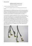
Remove the standard linkage arm, making a note of the position of the shift lever. Now fit together the
STRAIN GAUGE with an HM Linkage Kit (available separately) to achieve the same overall length as the
standard linkage.
Re-install the shift linkage making sure that the STRAIN GAUGE and the cable exiting the STRAIN
GAUGE will not foul the gear lever or any other mechanism.
It is preferred to fit the STRAIN GAUGE nearest the gearbox.
The Strain Gauge Sensor has two female threads. These are special DUAL THREADS and each of
these threads will accept a LEFT or a RIGHT thread.
Important Points:
1. The Sensor and Shift rod must be free on the rose joints. This means that you should be able to rotate
the sensor and linkage rod at least a small amount on the rose joints.
2. The sensor and linkage rod must not hit or foul anything. Move the lever through its entire range
of travel and make sure that the sensor and linkage rod are free to move without touching anything or
straining the attached cable.
3. The wire between the sensor and the LCD box can be damaged by pulling hard or by cables ties being
too tight.
Installing the LCD Control Box
Find a suitable place on the motorcycle (typically under the seat) and route the wires to the linkage in a way
that will keep them clear of possible damage.
Copyright © 2014 HM Quickshifter UK, Ltd.
Installing the LCD Control Box -- Page 9 of 17
HM Plus SS User's Guide
Connecting to the Electrical System
As of this writing, the HM Plus SS, comes in several varieties, depending on the motorcycle onto which it
will be installed:
Model
Motorcycle
HM Plus SS SH
Suzuki & Honda
HM Plus SS YK
Yamaha (not R6 up to 2004) and Kawasaki
HM Plus SS TRI
Triumph
HM Plus SS DUCATI
Ducati
HM Plus SS KTM
KTM
HM Plus SS BMW
BMW
HM Plus SS RSV4
Aprilia
HM Plus SS MV
Aprilia
Most HM Plus SS models connect directly to the plug top coils and have many benefits. One of these
benefits is that it is completely independent of the ECU and motorcycle loom (wiring harness). It also shifts
much better than almost any ECU.
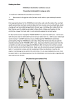
Wiring: The supplied loom simply plugs in-line with the Ignition Coils. The only other connection is the
ground strap which must be connected to a reliable ground (NOT the valve cover [cam cover]).
CAUTION: The sub-loom has a label on it ("YK", "SH", etc.). It is very important that the subloom matches the motorcycle it is being installed on. On the BMW S1000RR, connect the subloom to the fuel injector plugs on the back of the air box. Refer to FAQ for full loom guide for other
motorcycles.
Setup -- Page 10 of 17
Copyright © 2014 HM Quickshifter UK, Ltd.
HM Plus SS User's Guide
Setup
The HM Plus SS is already set up for your motorcycle.
If however, you would like to fine tune the quickshifter then this is easily achieved via the LCD.
There are three or four different setting that can be adjusted, depending on your model:
1.
2.
3.
4.
COMPRESSION / EXTENSION
SENSTIVITY
KILL TIME
HMSS (On / Off)
To enter SETUP MODE:
1. Switch motorcycle off so that the HM Plus SS is turned off.
2. Press and hold the shift lever in either direction and switch the motorcycle on so that the HM Plus SS is
powered up. The display will count down: 5-4-3-2-1-0.
3. Release the shift lever when the LCD displays 0.
The HM Plus SS is now in SETUP MODE.
Compression / Extension
The HM Plus SS LCD will now be displaying:
.
or
or
The characters will be flashing.
stands for "extension" and
stands for "compression". Look at your shift linkage and determine if it
needs to be compressed or extended to perform an up-shift.
To change to the setting, simply press and release the shift lever in either direction.
If both
and
are displayed, then the quickshifter is set up to cut the ignition for both directions. It is
NOT advisable to use this setting unless it is really needed, such as for endurance racing where one rider
rides with a race pattern and the other with a road pattern.
Copyright © 2014 HM Quickshifter UK, Ltd.
Compression / Extension -- Page 11 of 17
HM Plus SS User's Guide
To move to the next setting (Sensitivity), press and hold the shift lever for approximately 2.5 seconds. The
the LCD will now display the Sensitivity setting.
Sensitivity
The sensitivity is how much force needs to be applied to the gear lever before a quickshift is initiated. The
HIGHER the number, the MORE sensitive the quickshifter will be. The LOWER the number, the more
pre-loading will be placed on the shift drum before the shift (ignition cut) is performed. Lower sensitivity
settings generally promote smoother and faster shifts.
The display will flash the sensitivity setting between 5% and 100% in 5% increments and will look like this:
To change sensitivity, simply press and release the shift lever. To change the value to a higher sensitivity,
press the shift lever so that it COMPRESSES the shift linkage. To change it to a lower sensitivity, press the
shift lever so that it EXTENDS the shift linkage.
WARNING: If a very sensitive setting is selected, there is a risk of false neutrals or missed gears. Try and
choose a setting that requires normal force to the shift lever (similar to the amount of force that would be
required without the quickshifter).
To move to the next setting (Kill Time), press and hold the shift lever for approximately 2.5 seconds. The
the LCD will now display the Kill Time setting.
Kill Time
Kill Time is the time gap (in milliseconds) that the ignition is cut to relieve stress on the gearbox to allow for
a gear change. The display will flash the Kill Time in milliseconds in the range of 30 to 150 and will look
something like this:
To change the Kill Time, simply press and release the shift lever. To change the value to a higher value,
press the shift lever so that it COMPRESSES the shift linkage. To change it to a lower value, press the
shift lever so that it EXTENDS the shift linkage.
WARNING: If the kill time is too short then the gearbox may be damaged. A kill time too long will cause
the motorcycle to "lurch" during shifts. A kill time of 60 is considered optimal for a typical superbike with a
"slick" gearbox.
Sensitivity -- Page 12 of 17
Copyright © 2014 HM Quickshifter UK, Ltd.
HM Plus SS User's Guide
To save the settings and exit setup mode, press and hold the shift lever for approximately 2.5 seconds.
The display will instead proceed to the next setting (HMSS On / Off).
HMSS On / Off
TM
HMSS stands for HM Seamless Shift Technology
and is thoroughly described in the HM Seamless Shift
Technology (HMSS) page. After saving the Kill Time setting, the display will show the HMSS setting and
will look something like this:
or
To change the setting, simply press and release the shift lever in either direction.
To save the settings and exit setup mode, press and hold the shift lever for approximately 2.5 seconds.
The LCD will display "CA" momentarily until you release the shift lever. Then the LCD will display the
normal operation display. The quickshifter is now ready for operation.
Copyright © 2014 HM Quickshifter UK, Ltd.
HMSS On / Off -- Page 13 of 17
HM Plus SS User's Guide
Calibration
The HM Plus SS does require calibration, but this is fully automatic.
A calibration is performed immediately upon power up, and the shifter re-calibrates itself continuously
during operation. If there was a significant change since power off, such as might be caused by a
significant temperature change, the display will briefly display "CA" while the shifter is re-calibrating, and
then proceed to the normal operation display once re-calibration is complete.
Stationary Test
Once the installation is complete, it may be desirable to do a test while the motorcycle is stationary. This is
a two part test.
PART 1
Turn the ignition on so that the LCD is visible. With the engine OFF, and while watching the LCD push/
pull the shift lever in the direction that would shift gearbox to the next higher gear (UP for road pattern
and DOWN for race pattern). The LCD display should flash "SHIFT". The ideal sensitivity is when the
lever needs slight more force than is required to engage the next gear. If the LCD does not flash "SHIFT",
increase sensitivity until it does, just for this test. Also make sure that the C and E are the right way round.
PART 2
Sit on the motorcycle and put it into 6th gear. Hold the clutch in and keep it held in for the duration of this
test. The motorcycle must not move. If you can, also hold the brake on. Now start the motorcycle and
raise the RPM to a steady 4000 RPM or above. While holding the engine at this steady RPM, try and shift
into an imaginary 7th gear. Every time you do you should hear the engine RPM dip for a split second.
Operation
Once the installation is complete and the HM Plus SS's operation is confirmed, you are ready to enjoy
limitless quickshifting. Once the clutch is fully released in 1st gear, use of the clutch is optional thereafter
while up-shifting.
You will achieve the best performance by shifting using a firm, assertive motion with the shift lever. Lower
sensitivity settings tend to help achieve this.
The HM Plus SS will only initiate an ignition cut once per quickshift. The shift lever must be released
before another quickshift will be initiated.
Stationary Test -- Page 14 of 17
Copyright © 2014 HM Quickshifter UK, Ltd.
HM Plus SS User's Guide
Frequently Asked Questions
Q: Why does the LOOM not fit the connectors on my motorcycle?
A: You are trying to plug the connectors into the injectors. The supplied loom fits the ignition coils
(under the front of the airbox).
Q: Why is the shifter not shifting?
A: Turn the motorcycle on so that the LCD is shown. Now push or pull the lever until "SHIFT" flashes on
the LCD.
If "SHIFT" does flash, then be sure that it is shifting the right way round (check the C and E setting).
If "SHIFT" does not flash up then set the sensitivity to 100% just for this test and try again, if shift still
does not flash up then contact HM Quickshifter.
Q: Why every time I change my settings does the LCD turn off after a second or two?
A: Some motorcycles energise the primary ignition circuit to prime the fuel pump, and when fuel
pressure is reached, the ECU will turn off the primary circuit until you start the motorcycle. In this case
you will need a friend to start the motorcycle and hold in the clutch while you press and hold the shift
lever to get into setup mode. Make sure that the clutch is held in!
Q: Why do I sometimes hit a false neutral?
A: The sensitivity is too high. Reduce the sensitivity until you can feel that you are being assertive on
the gear lever. Remember the lower the sensitivity, the faster and smoother the gear change!
Q: Why does the shifter sometimes shift and sometimes not?
A: You have the sensitivity way too high. The shifter needs to detect when you have let go of the lever
so that it can allow the next shift. If the sensitivity is too high, the shifter may not detect that you have
released the lever and therefore will not allow another shift.
OR
You are inadvertently leaving some pressure on the lever or resting your foot on the lever. This is
common even among the best riders.
Q: Why is there a C and an E mode together, surely I can just leave it like this.
A: The shifter is shipped in both C and E modes, this is so that you can simply fit the shifter and use
it without adjusting any settings. Also some endurance race teams have one rider that rides in road
pattern and the other rider uses race pattern.
However it is better if you set it up in either C or E so that it is correct for your motorcycle. The reason
for this is that the motorcycle may stall when changing into first gear from neutral when the engine is at
idle and the other reason is that the shifter is a complex piece of electronics with a processor constantly
calculating the best possible shift. You will be making its job easier if you choose the right shift direction.
Copyright © 2014 HM Quickshifter UK, Ltd.
Frequently Asked Questions -- Page 15 of 17
HM Plus SS User's Guide
There is a fitment (connection) guide of what loom (wiring
harness) you require for your type of motorcycle, please see the
FAQ section on our website: http://www.hmquickshifter.com .
Failure to do so, could really damage your motorcycle!
Incorrect wiring damage is not covered by warranty.
Specifications -- Page 16 of 17
Copyright © 2014 HM Quickshifter UK, Ltd.
HM Plus SS User's Guide
Specifications
Minimum voltage
5.1V
Maximum voltage
16V
Maximum transient
60v, <100ms
Current consumption
<25mA
Output maximum current
35A
LCD shock limit
3G (1G = 9.8m/s²)
LCD functional temperature
0ºC to 80ºC
LCD maximum temperature
-20ºC to +90ºC
System functional temperature
-40ºC to +125ºC
Absolute Maximum Ratings:
Maximum voltage
Maximum load current
16V
250mA
NOTE: If the LCD is taken beyond its functional temperature, it will not be readable but will recover after
some settling time once it functional range is restored.
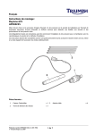
The orange wire is effectively connected to 12V as supplied by the electrical supply that normally powers
the plug-top coils (commonly the ECU), and the grey wire is the 12V output from the shifter. During a
SHIFT, the 12V feed to the grey wire is interrupted for the duration of the Kill Time.
Copyright © 2014 HM Quickshifter UK, Ltd.
Specifications -- Page 17 of 17