1
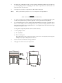
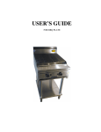
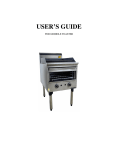
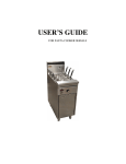
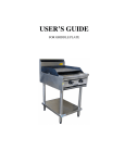
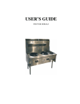
USER’S GUIDE
FOR OVEN RANGE AND COMBINATION
SPECIFICATION
NAME OF APPLIANCE
SUPERTRON COMMERCIAL OVEN
MODEL NO.
4BT-OV-600, 6BT-OV-900, 8BT-OV-1200,
10BT-OV-1500
TU’S BROS PTY LTD
77 MAIN ROAD, CLAYTON SOUTH
VIC 3169 AUSTRALIA
5910
MANUFACTURED BY
CERTIFICATE NO.
General Description
A Heavy duty commercial oven direct fired to give maximum oven usage. Also designed with Boiling Top.
The oven features two side hinged doors with a combination minisit thermostat and flame failure valve, with piezo
ignition to oven pilot with a 215mm splashback and mounted on 150mm adjustable legs.
The boiling table can be supplied separately mounted on 609mm legs when an oven is not required in models of the
above description with splashback.
Overall Dimensions
Height over splashback
Width
Depth (front to back)
Height to Hotplates
Leg Height
Weight
Hi Limit Capillary Location
Test Point Pressure
Injector Ø mm
Nominal Gas Consumption (MJ/h)
Markings
Construction
Main Frame
Outer Panels
Oven Interior
Oven Doors
Gas Point Entry
Gas Injectors
Burner Type
Burner Head
1130mm
600mm (4BT-OV-600), 900mm (6BT-OV-900), 1200mm
(8BT-OV-1200)
825mm – includes knob
915mm from floor
150mm adjustable
Approx. 80kg
(Bulb) 210mm from top of pan ledge x 50mm centres
NG: 1 KPa
LPG: 2.75 KPa
Boiling
Griddle
Oven
Boiling
Griddle
Oven
Plate
Plate
1.80
1.90
1.95
1.00
1.10
1.20
17.00
18.50
19.80
14.00
15.35
20.00
Supertron on Splashback
Marking “On” “Off” front and rear on control panel
Date Plate on Front Panel
Serial No.
Cat. No.
N.H.G.C.
Test Point Pressure
Lighting Instruction Plate
25x25x2mm Square Tube
304/No4/1.2mm stainless steel
Mild steel with enameled
Stainless steel 304/No4/1.2 insulated
Fitted with stainless steel hinges and ball catch
A ¾" /20 Comp connection located on the right hand side which
supplies gas to the thermostat and gas manifold and thermostat.
The gas point entry is the same location where boiling tables are
supplied separately.
12.7mm hexagon 25.4mm long x Ø11mm. Nozzle 15mm long,
3mm B.S.P. thread x 6mm long.
Cast iron burner with vertical slotted port.
Cast iron Ø91mm x 2mm slot removable from burner body
2
Mixing Tube & Throat
Venturi 108mm long – Taper 19mm to 12mm. Primary air
12mm to 38mm taper at injector entry. Round in Shape.
Primary Air
Interrupter screw and locknut 9.5 witworth x 31mm long from
inlet. Air drawn into burner venture around injector nozzle.
Burner Support
Burners are supported off 25mm x 25mm square section tube
welded frame with supporting plate to locate burners.
Vessel Clearance
Secondary Air Entry
Trivets
Distance from highest point of trivet to burner port 67mm
Through sides of burner frame and rear of appliance.
Cast iron vitreous enameled 270mm x300mm with support
fingers
Vitreous enameled pressed sheet metal (round)
Stainless steel section 900mm wide x 250mm high x 75mm
depth
Located in top of splashback x 75mm full length slot.
Spillage bowls
Splash Back
Flue Outlet
OVEN DESCRIPTION
Direct fired with the products of combustion passing out of the oven by means of 2 circular outlets located near the top
of the oven. Each outlet is Ø60mm x 395mm up from the base of the oven x 125mm in from each side.
The outlets discharge into 2 vertical flue ducts fastened to the rear of the oven. The flue ducts terminate into the
splashback. Flue ducts are 90mm wide x 35mm deep.
The oven burner is located in a burner box at the rear of the oven and is recessed. A oven crown tray is located above
the oven to collect spillage.
Oven Burner
Aeromatic 9R x 14 U/Slung (Keegas)
Oven Thermostat
Oven Pilot
S.I.T. combination flame failure thermostat. Ignition to the oven pilot is
by means of piezo ignition fitted adjacent to the thermostat. The oven
pilot is adjacent to the oven burner incorporating spark electrode and
thermocouple.
S.I.T. M42F adjustable.
Oven Shelves
Mild steel rod, plated incorporating a safety stop position.
Internal Oven Dimensions
W 645mm x D 520mm x H 470mm
Door Type
Side opening through 180 degrees. Insulated with rockwool fibre.
Secondary Air to Oven
Is supplied around burner box located at the rear of the oven.
Regulator
Maxitrol RV48M-66. App. No.3088
Flame Failure Control for
Grill
Keefer (KB) F90 Gas Valve with thermoelectric flame failure. App. No.
5852.
INSTALLATION INSTRUCTIONS
(By Authotised Personnel Only)
This appliance should be installed by authorized persons only and must be installed in accordance with AG601, 1995
refer Section 5-12.4 Catering Equipment and all clauses to 5.12.4.5.
GAS PIPING SYSTEM
The gas inlet to the appliance is located on the right hand side at the rear of the unit. The connection point is 610mm
above the floor into a tee piece, entry facing down. The distance in from the right hand side of the appliance is 80mm
to centre of the tee.
3
The unit is supplied with a ¾” B.S.P. regulator – the installer must supply a ¾” B.S.P. gas cock to enable isolation of
the appliance for servicing. The unit must have at least a 1” B.S.P. (25mm) pipe up to the connection point, with a
minimum pressure of no less than 1.13 KPa inlet. A minimum appliance operating pressure of no less than 0.1 KPa
with 60% of the appliance operating. The installer must use a monometer to check the pressure and test for leaks.
Test points are provided off the oven control and off the gas cock manifold. Alternatively a burner injector may be
used off the top burner and the manometer tube placed firmly over the injector after removing the burner.
The appliance must be installed to local Health Dept. and gas fitting regulations.
For test point pressure settings refer to data plate on the appliance.
If unit fails to operate, please contact local distributor or call manufacturer on Phone: (613) 9543 9577 Fax: (613) 9544
1487.
CONVERSION INSTRUCTIONS: from NG to LPG
1.
Conversion must not be carried out without consulting manufacturer or agent in the region.
2.
(a) Remove NG injectors
(b) Remove NG regulator
(c) Replace pilot injector with LPG type
(d) Set appliance operating pressure to 2.75KPa
OPERATING AND MAINTENACNE INSTRUCTIONS, SERVICE
6 Burner boiling top /oven range
4 Burner boiling top/oven range
These instructions must be read carefully prior to initial use and retained in a safe place.
BOILING BURNERS
All boiling burners require manual ignition, turn knob anti-clockwise after depressing knob to on position. Apply
match or taper to light burner.
LIGHTING GRILL PLATE
Turn gas cock knob to pilot position, press in and press piezo spark button 2 or 3 times to ignite pilot. When pilot is lit,
this can be seen through a viewing hole in control panel. Turn gas cock knob anti-clockwise and select flame height as
required i.e. low position is marked. To turn pilot off , turn gas cock to the full off position.
OVEN OPERATION
The oven burner is located at the rear of the oven. On the right hand side of the oven burner is the pilot spark ignition
and thermo electric safety thermocouple.
LIGHTING OVEN PILOT
1.
Press button marked with flash H symbol, hold in for approximately 5-8 seconds (hold until spark ignites
pilot).
2.
Press button marked with lighting symbol several times until pilot stays alight.
3.
Turn thermostat to required setting. Oven burner will then light.
4
4.
Should the piezo spark ignition fail, the oven pilot can be lit manually by holding in the top left button as
per normal lighting procedure and lighting pilot with match or taper. However, ensure that the oven
thermostat is in the off position first.
5.
To turn pilot off, press button on right hand side. Pilot will then extinguish.
Notice:
Where possible instruct operator how to use oven range before leaving installation
SERVICE
(Must only be carried out by Authorised Personnel)
1.
To service oven pilot, remove stainless steel oven base plate in front of oven burner and remove pilot
assembly from plate. The same procedure is applicable or service spark electrode and spark lead.
2.
To service thermostat remove screws anround panel, which will then come forward exposing the control.
Remove screws holding control to mounting bracket, undo top and bottom fittings attached to control.
Release thermostat bulb located on right ahand side of oven and pull forward, then release thermocouple
and spark lead ot replace control.
servicing thermocouple and spark lead is carried out in the same way.
3.
to service grill plate control:
(a) Lift off grill plate
(b) Remove control panel
Flame failure thermocouple, spark lead and electrode can now be serviced without removing panel.
Grill plates may require control panel to be removed.
4.
Test all connections for leaks before leaving installation
5.
Only approved controls to be used for replacement.
DIAGRAM
5