1
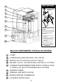
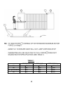
D3, D5, A5
SLIDING GATE
AUTOMATION
Product Code: CP72SR5
INSTALLATION
MANUAL
Latest Revision: 02.02.2005
Document Ref.: 1010.D.01.00136_8
30
IMPORTANT
31
Oil Specifications:
GRADE: 75W90
Qty: 75ml
OIL
LEVEL
32
33
34
35
WARNING! (D5/A5 ONLY)
Fill with oil prior to running
gearbox.
For transport purposes this
unit has been supplied with
oil in a separate sealed
container.
36
1. Lift off the cover to the
operator.
2. Remove the control card
and battery so that you
can gain access to the
filler plug.
3. Unscrew the cap and
pour in the oil provided
37
38
NB. D3 is pre-filled with
fluid grease.
MAJOR COMPONENTS (TYPICAL D5 SHOWN)
30
- COVER
31
- CONTROLLER (CP80 FOR D3/D5; CP81 FOR A5)
32
- MOTOR (12V DC FOR D3/D5; 220V AC FOR A5)
33
- BATTERY (12V DC, 7A/H-D3/D5 ONLY) (OR PSU1/2, IF FITTED)
34
- CHARGER TRANSFORMER/POWER SUPPLY (CP84E for D3/D5
or CP83E for A5) (NOT FITTED WHEN PSU1/2 IS USED).
35
- GEARBOX CASING
36
- INTERNAL LIMIT SWITCH (DOSS)
37
- MANUAL RELEASE THUMBWHEEL
38
- LOCKABLE ACCESS DOOR
1
TABLE 1
RUN (kgF)
START (kgF)
D3
25
GATE MASS (kg)
12
300
D5
60
20
500
D5 Light Industrial
16*
16*
500
A5
22
22
500
*LIMITED BY CAPACITY OF PSU
2
ANTI-LIFT BRACKETS
- Guide rollers 39 must ensure that the gate is held vertically.
- Fit suitable anti-lift brackets 42 . The gap 40 should be <5mm to ensure
the gate cannot be lifted off the motor pinion.
- For improved safety fit additional support post 41 to prevent gate from
falling over if guide rollers 39 fail.
3
D5
A5
120
100
80
60
40
5
Pull ( kgf )
Time (hrs)
A5 with FAN
Duty Cycle ( % )
120
100
80
60
40
20
30
25
20
15
0
5
0
Time (hrs)
DUTY CYCLE CURVES
- FOR THE WARRANTY TO BE VALID, ENSURE THAT THE DUTY CYCLE
IS NOT EXCEEDED FOR THE PARTICULAR MOTOR BEING USED.
* - DUTY CYCLE IS SUBJECT TO BATTERY AND CHARGER SIZE.
4
30
20
25
56
48
41
36
20
67
15
Duty Cycle ( % )
81
6
8
10
12
14
16
18
20
22
24
26
28
30
Duty Cycle ( % )
*
100
6
5
7
2
9
11
3
8
10
4
RECOMMENDED INSTALLATION AND
CABLE THICKNESS REQUIREMENTS†
2
- LOCAL ISOLATOR
3
- MAINS SUPPLY (min 0.5mm² ‡, 2 CORE + EARTH)
4
- INTERCOM AND STATUS SIGNALING TO HOUSE
(0.2mm², *n1 + 6 CORE)
5
- INTERCOM TO GATE STATION (0.2mm², #n2 CORES)
6
- PILLAR LIGHTS (0.5mm², 2 CORE + EARTH)
7
- RADIO RECEIVER (0.2mm², 3 CORE)
8
- PEDESTRIAN KEYSWITCH (0.2mm², 2 CORE)
9
- INFRA RED BEAM (0.2mm², 3 CORE)
10
- FREE EXIT LOOP (1.5mm², multi stranded cable)
11
- FREE EXIT CONTACT (0.2mm², 2 CORE)
† For cable types to be used (e.g. SWA, Cabtyre, Intercom cable etc.) consult your
municipal authority for details.
* n1 = NUMBER OF CORES REQUIRED BY INTERCOM
# n2 = NUMBER OF CORES REQUIRED BY INTERCOM
‡ sufficient for motor only, increase to suit total load if pillar lights are fitted
5
MECHANICAL MOUNTING DETAILS
Option 1 - Bolt down onto concrete plinth
- Ensure motor does not protrude into drive-way install baseplate
with centre line 250mm off pillar centre.
- Position baseplate (43) with centre of single support stud (45) 105mm
from edge of gate (46). (This dimension assumes centre line of rack (47)
is 20mm from edge of gate).
- Using the baseplate as a template mark and drill the 4 mounting holes
into the concrete for the four M10 x 95 expansion studs.
- Use two M12 plated nuts per expansion stud as spacers below the
foundation plate.
- Secure the baseplate to the expansion studs using one M10 washer and
nut per expansion stud.
43
47
45
105mm
20mm
CL
6
46
M10 Nut
M10 Washer
Use two M12 plated
nuts as spacers.
M10 x 95 expansion stud
250m
m
CL
Existing concrete plinth
7
43
43
47
46
45
44
44
105mm
250m
m
20mm
CL
CL
300mm
400mm
400mm
MECHANICAL MOUNTING DETAILS
Option 2 - Set into concrete plinth
- Ensure motor does not protrude into drive-way install baseplate
with centre line 250mm off pillar centre.
- Fasten concrete anchors (44) to the baseplate (43) using the M10x45
bolts provided. Ensure that the bolts are well tightened.
- Position baseplate (43) with centre of single support stud (45) 105mm
from edge of gate (46). (This dimension assumes centre line of rack (47)
is 20mm from edge of gate).
8
350 mm
30 mm
46
47
43
PROVISION FOR CABLES
- Ensure cables 46 are fitted through base plate 43 before concreting
in place.
- Remove knock-outs 47 from gearbox to allow for cable entry.
- Route cables in front of battery (D3/D5 motors) as shown above.
- Seal cable entry holes with silicone sealer.
9
54
53
7
52
mm
54
51
GEARBOX MOUNTING DOWN DETAILS
- Leave at least 7mm clearance between the lower gearbox nuts 52 and
the baseplate to allow for later adjustment.
- Gearbox MUST be firmly located between top & bottom nuts and washers
54 as shown at 51 . Use spring washer 53 to lock top nut in place.
- Slide gearbox forwards or backwards to give ±8mm clearance between
front of pinion and edge of gate.
10
55
±300 mm
56
57
MOUNTING RACK
- Attach steel rack to gate using 25x25x2mm angle brackets 55 . Distance
between centerline of rack and edge of gate should be 20mm (see 56 ).
- For best results support rack every 300mm.
- Rack must be mounted level with a 2 - 3mm clearance 57 .
USEFUL TIP
l
l
l
l
11
Raise gearbox by an additional 3mm.
Put gearbox into manual mode
(see........
37 on page 22)
Mesh rack and pinion fully and mount rack.
Slide gate backwards and forwards
ensuring that rack mesh is smooth and
never tight.
Drop gearbox by 3mm to create 3mm tooth
clearance.
59
58
200 - 300mm
LEVEL
200mm
60
MOUNTING RACK CONTINUED
- A simple way of ensuring correct pitch spacing when joining steel rack is
to clamp a small offcut 58 between the two pieces.
- Check that weld 59 does not foul with meshing surfaces.
- If RAZ ™ rack 60 is used, then start installing from the right hand side of
the gate working towards the LHS. Use fastening screws e.g. “TEK” screws
at least every 200mm.
12
65
IDLER
PULLEYS
64
>100mm
61
>100mm
62
63
INSTALLING CHAIN DRIVE SYSTEMS
- Weld rear anchor plate 61 onto gate such that centre line of tensioner
pin 62 is in line with top of the shaft on the idler pulley 64 . Allow at least
100mm between idler pulleys and anchor brackets.
- Align fixed anchor bracket 63 as for 61 .
- Ensure chain direction over sprocket is as shown (see 65 ).
13
6mm
13mm
<15kgF
SETTING MECHANICAL CLUTCH (A5 ONLY)
- Isolate MAINS POWER.
- Remove fan from motor to expose the motor shaft (where applicable).
Ensure fan has stopped turning.
- Lock shaft using 13mm spanner and use 6mm allen key to adjust
sensitivity - Clockwise to increase force.
- Recommended maximum push force should not exceed 15kgF.
14
MOUNTING CONFIGURATION
FOR STEEL RACK
BOLT USING
FASTENERS
PROVIDED
66
WELD
MOUNTING
BRACKET
PROVIDED TO
STEEL RACK
A
HA
RT
TE
A
E
GR
ORIGIN MARKER
BRACKET
0
N5
0m
m
68
66
GREATER THAN 500mm
B
66
66
C
13-20mm
68
MOUNTING OF GATE SENSOR
- With the gate in the CLOSED position, mount the origin marker (66) a minimum
500mm from the origin sensor (68). (See isometric view (A) or plan view (B)
above).Please note this distance will affect the pedestrian opening distance. For
minimum pedestrian opening, mount the origin marker at 500mm. The
maximum distance of the origin marker is limited by the marker having to pass
the sensor by no less than 500mm before the gate opens fully. If a longer
crawling distance is required, the position of the marker needs to be changed
(see table 3 on page 30).
- Manually slide gate OPEN until origin marker (66) is in line with the origin
sensor (68). Ensure distance between face of marker (66) and front face of
sensor (68) is between 13 and 20mm. (See (C) above)
- Adjust distance by sliding the origin marker (66) along the slotted mounting
holes until desired distance is achieved.
15
BLUE
E
COM
LIGHT
LIGHT
BATT +
BATT -
MOTOR
MOTOR
COM
LIGHT
CP80 PSU1
LIGHT
BATT -
MOTOR
MOTOR
12
N
LIGHT COM
GREEN/YELLOW
L
BROWN
M1 M2 M3
BATT +
CP80
CP81
17
15
M
M
16
16
15
15
E
E
NL
NL
75
13
L
N
E
EN L
L
N
E
21
13
76
18
14
20
-
BATT
BATT +
19
19
13
L
N
E
21
17
POWER WIRING (SEE PAGE 15 FOR SIGNAL WIRING)
- 220V AC MOTOR WITH STARTING CAPACITOR
13 - 220V AC, 1Ø, MAINS SUPPLY FOR CP84E / CP83E USING
REMOVABLE CONNECTORS
14 - CP83E POWER SUPPLY TRANSFORMER (A5 MODEL ONLY)
15 - 220V AC PILLAR LIGHT (NOT AVAILABLE ON CP84XTE PSU)
16 - 12V DC MOTOR
17 - 12V DC LEAD ACID BATTERY (Amp/HOUR RATING TO SUIT)
18 - CP84E CHARGER TRANSFORMER (D3/D5 MODEL)
(OR CP84XTE WHEN USED WITH PLUG-IN TRANSFORMER)
19 - LIGHTNING EARTH POINT
20 - 12V DC PLUG TO CP81 CONTROLLER
21 - 14.2V DC CHARGE PLUG TO CP80 CONTROLLER
75 - PSU1/2 - POWER SUPPLY UNIT
76 - MAINS FUSE - PSU1/2
NOTE: External battery not necessary but if fitted then CP80 PSU1
*controller
must be fitted.
12
16
*
NEG
12V
COM
N/O
NEG
12V
NEG
12V
24 COM
N/C
SET
LCK
PED
LED
FRX
IRB
TRG
+12V
COM
COM
LIGHT
LIGHT
CP80 / CP81
22
23
25
26
27
28
29
SIGNAL WIRING (CP80 AND CP81)
22
- RADIO RECEIVER (OR OTHER TRIGGER e.g. INTERCOM)
23
- INFRA RED BEAM TRANSMITTER
24
- INFRA RED BEAM RECEIVER (N/C CONTACT)
25
- FREE EXIT TRIGGER (N/O CONTACT)
26
- REMOTE STATUS LED (MAX 3 IN PARALLEL)†
27
- PEDESTRIAN TRIGGER (N/O CONTACT)
28
- HOLIDAY LOCKOUT CONTROL (N/C LATCHING CONTACT)
29
- REMOTE PILLAR LIGHT CONTROL (N/O CONTACT)
= LED INDICATORS ON P.C.B. SHOWING STATUS OF INPUT SIGNALS
† = USE MULTI LED DRIVER CARD (CP78) FOR MORE LED’S
17
31
34
50
ENL
220V AC
LNE
INPUT 220V AC OUTPUT
49
TO CP80/CP81
PCB "DC IN”
43
48
RECOMMENDED LIGHTNING PROTECTION
- For optimum lightning protection ensure earth cable from charger/PSU unit
34 is adequately earthed.
- Use ring lug 49 to bond to baseplate mounting stud.
- For additional protection bond baseplate 43 to earth spike 48 .
- In event of damage to charger/PSU unit 34 disconnect quick release link
50 and push-on connector on controller.
18
1
2
3
4
5
END
COMMISSIONING BLOCK DIAGRAM
1
- Check correct motor direction (pg. 20)
2
- Select programme mode (pg. 21)
3
- Setting of gate limits (pg. 22-27)
NOTE: D3/D5 LIMITS ARE SET AUTOMATICALLY.
A5 LIMITS ARE SET MANUALLY
4
- Function Selections(optional) (pg. 27-28)
5
- Timer/counter settings (optional) (pg. 29-30)
Steps 1 to 3 must be done on initial commissioning.
Steps 4 & 5 are optional.
19
CP80
CP81
12V DC
220V AC
MOTOR
a
M1 M2 M3
b
a
TO 12V DC MOTOR
c
b
TO 220V AC MOTOR
SETTING MOTOR DIRECTION
CP80
GATE CLOSES: -
a
TOWARDS LEFT (ABOVE) BLACK
TOWARDS RIGHT
BLUE
CP81
b
a
b
c
BLUE
BLUE
BLACK
RED
BLACK
RED
BLACK
BLUE
ENSURE THAT MOTOR WIRE COLOURS ARE AS PER TABLE ABOVE
20
1
CP80/CP81
2
L1
13.8V
L2
CP80/CP81
L1
3
L2
CP80/CP81
L1
L2
STATUS
STATUS
STATUS
SET
SET
BLACK
72
SET
RED
69
71
70
SELECTING PROGRAMME MODE
STEP 1 - Remove power from control card:
- for A5 remove electronics power only 69
- for D3/D5 remove battery power 70 as well as electronics
power 69 .
STEP 2 - Fit “SET” link 71 .
STEP 3 - Reapply power (reversal of STEP 1). STATUS LED will flash 5 times
on power up. Check that LED L2 and “SET” are ON.
LED L2 72 indicates controller is in “programme mode”.
21
Fig.1
1/2
1/2
73
37
Fig.2
SETTING GATE LIMITS
- Rotate manual release thumbwheel 37 fully clockwise, or until clutch is
fully dis-engaged and gate can be moved by hand.
D3/D5 ONLY
- Slide gate approximately half way open. See 73 above (FIG. 1).
- Re-engage gearbox.
A5 ONLY
- Slide gate to fully closed position (FIG. 2).
- Leave gearbox dis-engaged.
- Skip to page 25-27 and follow START MANUAL GATE LIMITS ROUTINE.
22
CP80/CP81
control card
L1 L2
TEST
STATUS
SET
SETTING GATE LIMITS (continued)
NB. Ensure you follow the correct procedure!
The procedure for setting D3/D5 and A5 motors is DIFFERENT.
The A5 limits have to be set manually (see page 25 and 26), while
the D3/D5 motors set their limits automatically (see page 21 to 23).
D3/D5 ONLY (PAGE 23, 24, 25)
- Press the TEST pushbutton while monitoring LED L1.
- When L1 flashes once, release TEST pushbutton. L2 will go out,
L1 will continue to flash once per second. Controller is now in MENU 1
which sets gate limits.
NB. Understand the procedure detailed on page 24 before continuing.
The controller is about to perform the fully automatic setup routine.
CP80/CP81
control card
L1 L2
TEST
STATUS
SET
START AUTOMATED GATE LIMITS ROUTINE
- Press TEST pushbutton until STATUS LED illuminates.
- AUTOMATIC set up routine (described on page 24) starts as soon as TEST
button is released.
23
D3/D5 MOTOR AUTOMATIC SET-UP
1
1- Gate starts at “crawl” speed to open
gate.
NB. If gate closes, remove power and
reverse motor wires (see page 20)
2
2- Gate hits “open” end stop and reverses
direction running at crawl speed.
3
3 - Gate hits “closed” end stop and
reverses direction running at “FULL”
speed until the marker, then at
CRAWL speed to end.
4
4 - Gate hits “open” end stop and
reverses but now runs at “FULL”
speed.
5
6
5 - As gate sensor passes the motor, the
speed reduces to CRAWL. Gate hits
“closed” end stops and reverses
at FULL SPEED.
6 - Gate stops at “pedestrian” (PED)
position. If required, widen PED
opening by pulsing PED input.
24
TURBO MODE: If desired the set up time can be shortened by manually
overriding the automatic “crawl”speed in steps 1, 2, 3 shown on page 24.
This is done by pressing and holding the TEST button. The speed increases
to FULL speed while the button is depressed.
NB. Do not run the gate into the end stops at full speed.
CP80
control card
CP80
control card
L1 L2
TEST
STATUS
74
L1 L2
TEST
STATUS
SET
SET
EXIT GATE LIMITS ROUTINE (D3/D5 ONLY)
- After the gate stops at the required pedestrian position (see step 6 on
page 24) ie either at the automatic minimum or the manually over-ridden
position, press the TEST button for a moment and release.
- L2 will illuminate when TEST button is released.
- Remove SET link and position as shown above, 74 , to exit programming
unless proceeding to other menus.
NB. If automatic routine does not complete (indicated by STATUS flashing
5 times & L2 illuminating) then it may be necessary to set collision
sensitivity to MED or LOW (see page 28)
START MANUAL GATE LIMITS ROUTINE
A5 ONLY (PAGE 26 & 27)
25
A5 MOTOR MANUAL SET-UP
STEP 1 ALIGN ORIGIN SWITCH
- Start with gate fully closed.
- Push gate open (origin marker must have
moved well past origin switch).
- Push gate closed again.
STEP 2 - ENSURE PCB IS IN PROGRAMME
MODE (refer procedure page 21)
STEP 3 - SET LIMITS
- Press TEST pushbutton until LED L1 flashes
once and release.
- L1 will continue to flash once and L2 will
go out.
- Press TEST pushbutton until STATUS LED
comes ON and release (check that L1, L2 &
STATUS are OFF)
STEP 4
- Push gate to fully “OPEN” position and do not
allow gate to reverse.
- Press TEST pushbutton until STATUS LED
comes ON and release.
STEP 5
- Push gate to fully “CLOSED” position hard
up against endstop and do not allow gate
to reverse.
- Press TEST pushbutton until STATUS LED
comes ON and release.
STEP 6
“PED”
- Push gate to “PEDESTRIAN” open position.
- Press TEST pushbutton until STATUS LED
comes ON and release. If STATUS LED
does not come ON, increase pedestrian
opening until it does.
26
CP81
control card
CP81
control card
L1 L2
TEST
STATUS
74
L1 L2
TEST
STATUS
SET
SET
EXIT GATE LIMITS ROUTINE (A5 ONLY)
If the gate limits described on page 26 are successfully completed,
then LED L2 will be ON.
- Position SET link as shown above 74 to exit programming unless
proceeding to other menus.
FUNCTIONS SELECT
Several different functions can be programmed. The procedure which is similar for all
functions is described below in conjunction with TABLE 2 on page 28
STEP 1 - Ensure controller is in Programme Mode (see page 21).
STEP 2 - Press and hold the TEST pushbutton while monitoring LED L1.
STEP 3 - L1 will flash once then go off, twice in short succession then go off, 3 times
then go off, etc. The number of flashes represents the menu number.
STEP 4 - Release TEST button when the required main menu (see Table 2, page 28) is
selected.
STEP 5 - To select the sub-division of the main menu (see RHS of Table 2), press and
hold the TEST pushbutton, while monitoring the STATUS LED to count
flashes. The number of times the STATUS LED flashes represents the sub
menu number.
STEP 6 - Release TEST pushbutton when the required subdivision is selected. L2 will
come ON to indicate that the controller is back in PROGRAMME MODE and
another FUNCTION or TIMER (refer to procedure on page 29) can be
programmed.
STEP 7 - Remove SET link when all programming is complete.
27
TABLE 2
MAIN
MENU
SUB DIVISION
OF MAIN MENU
No of times
L1 flashes
AUTO CLOSE
No of times
STATUS must flash
2
4
MODE
COLLISION
SENSITIVITY
7
POSITIVE
CLOSE MODE
9
PREFLASHING*
10
1
ON
2
OFF
1
STANDARD
2
CONDOMINIUM
3
PIRAC
4
REVERSING
1
HIGH
2
MEDIUM
3
LOW
1
ON
2
OFF
1
MODE1
2
MODE 2
3
MODE 3
4
OFF
FACTORY DEFAULTS HIGHLIGHTED
28
*The PREFLASHING MODES mentioned on page 28 are described below:
MODE 1 - COURTESY LIGHT PREFLASHES AT 1 HZ, THEN ACTS AS
COURTESY LIGHT.
MODE 2 - COURTESY LIGHT FLASHES AT 1 HZ FOR PREFLASH TIME
AND THEN FLASHES IN SYNCHRONISM WITH THE STATUS LED
WHILE THE MOTOR RUNS.
MODE 3 - COURTESY LIGHT ON CONTINUOUSLY FOR PREFLASH TIME
AND MOTOR RUN TIME ONLY.
TIMER and COUNTER SETTING
Various timers and counters can be programmed. The procedure is described
below in conjunction with Table 3, page 30.
STEP 1 - Ensure controller is in Programme Mode (see page 21).
STEP 2 - Press and hold the TEST pushbutton while monitoring LED L1.
STEP 3 - L1 will flash once then go off, twice in short succession then go off, 3
times then go off, etc.
STEP 4 - Release TEST pushbutton when the desired MAIN MENU item in Table
3 is required.
STEP 5 - To select required time (or count) hold TEST pushbutton while
monitoring STATUS LED. After a short time STATUS will flash
continuously and regularly. Each flash represents a unit of measure
(i.e. time, distance or count).
Release TEST pushbutton when the required subdivision is selected.
L2 will come ON to indicate that the controller is back in PROGRAMME
MODE and another TIMER or FUNCTION (refer to procedure on page
27) can be programmed.
STEP 6 - Remove SET link when all programming is complete.
29
TABLE 3
MAIN
MENU
UNIT OF
MEASURE
Each flash
No of times
of STATUS
L1 flashes
represents
FACTORY
DEFAULTS
NORMAL AUTOCLOSE
3
1 SEC
15 SEC
PEDESTRIAN AUTOCLOSE
5
1 SEC
5 SEC
COURTESY LIGHT
6
10 SEC
12x10 SEC
AUTOCLOSE OVERRIDE
8
1 SEC
3 SEC
PREFLASH TIME
11
1 SEC
5 SEC
COLLISION COUNTER
12
1 COUNT
4 COUNTS
CRAWL DISTANCE (D3/D5)
13
350 MM †
1x350mm
COAST MODE (A5)
13
10 MM
30mm
† THE CRAWL DISTANCE IS A LENGTH OF TRAVEL WHICH ALLOWS
THE GATE TO SLOW DOWN BEFORE REACHING THE END STOP. FOR
HEAVIER GATES WITH LESS FRICTION, THE CRAWL DISTANCE MAY
HAVE TO BE INCREASED. WHEN INCREASING THE CRAWL
DISTANCE, THE POSITION OF THE ORIGIN MARKER (ITEM 66 PAGE
15) MUST BE MOVED.
CRAWL STATUS FLASH
DISTANCE
COUNT
DEFAULT
DISTANCE BETWEEN
MARKER AND PINION
350mm
1
500mm
700mm
2
750mm
1050mm
3
1100mm
TURBO MODE: TO SPEED UP THE COUNTING WHILE SELECTING MAIN
MENU ITEMS TEMPORARILY CONNECT “PED” TERMINAL TO “COM”
30
PROCEDURE TO PROGRAMME CONTROLLER
BACK TO FACTORY SETTINGS
1. REMOVE POWER (POWER SUPPLY AND BATTERY IF D3 or D5).
2. FIT THE "SET" LINK.
3. CONNECT "PED" AND "FRX" TO "COM".
4. RECONNECT POWER. L1 AND L2 WILL ILLUMINATE.
5. REMOVE THE POWER (BATTERY AND POWER SUPPLY).
6. REMOVE THE "SET" LINK AND DISCONNECT "PED" AND "FRX" FROM "COM".
7. THE CARD IS NOW PROGRAMMED TO DEFAULT SETTINGS AS SHOWN IN
TABLES 2 (see page 28) AND TABLE 3 (see page 30) (GATE END POINTS ARE
NOT AFFECTED).
FAULT FINDERS GUIDE D3 / D5 OPERATORS
REF: CP157
EFFECTIVE: 19/09/2001
SUPERCEDE: 29/11/2000
SOME TYPICAL FAULTS
1. GATE RUNS A SHORT DISTANCE AND STOPS.
1.1 Battery low condition (Status flashing 3 times)
1.1.1 Old battery
1.1.2 Check battery charger
1.1.2.1 Charge voltage (13.8V no battery connected)
1.1.2.2 Charge rate (Check recovery rate of charger)
1.1.3 Check duty cycle of system (battery capacity sufficient)
1.1.4 Check condition of battery leads and connectors.
1.2 Multiple collision condition (Status flashing 4 times)
1.2.1 Adjust collision sensitivity (high to medium or to low)
1.2.2 Check for something physically obstructing the movement of gate
1.2.2.1 Rack pressing down onto pinion
1.2.2.2 Bad rack joints
1.2.2.3 Seized or badly running wheels
1.2.2.4 Top guide rollers restricting the gate
1.2.2.5 Dirt on rail
1.2.2.6 Physical damage to the rail
1.2.2.7 Wheel catching side of pinion
1.2.2.8 Gate hitting endstop
1.2.3 DOSS feedback problem
1.2.3.1 Dirt inside the DOSS
1.2.3.2 Poor connection between the DOSS and the controller (check cable and connector)
1.2.3.3 Doss cable fitted back to front
1.2.3.4 Doss not being driven due to missing coupling or faulty bevel drive.
1.2.3.5 Faulty DOSS controller
1.2.4 Faulty motor circuit
1.2.4.1 Motor fuseholder making intermittent contact.
1.3 Spurious trigger
1.4 Faulty controller
31
2. GATE DOES NOT RUN BUT THE RELAYS ENERGISE WHEN THE UNIT IS ACTIVATED.
2.1 Faulty motor circuit
2.1.1 Faulty motor relay / FET
2.1.2 Motor fuse blown (replace with 16/20A slow blow 5x20mm)
2.1.3 Fuseholder making bad contact.
2.1.4 Worn motor brushes
2.1.5 Loose motor wire
2.1.6 Faulty controller
3. GATE OPENS ON ITS OWN.
3.1 Permanent trigger input
3.1.1 Check for latched Rx or latched house pushbutton
3.2 Intermittent fault on pushbutton line (underground joint with moisture build-up)
3.3 Outside transmitter with the same code (typically only possible with compatible remotes QD black / TSM etc))
3.4 Faulty Rx
4. INTERMITTENT AUTO-CLOSE.
4.1 Latching Rx overrides auto-close
4.2 Long pulse on trigger input overrides auto-close (check pulse time of intercom gate release)
4.3 Faulty infra red beam input
4.4 Faulty controller
5. GATE DOES NOT RECOGNISE ITS LIMITS.
5.1 Magnet incorrectly mounted (Check page 13 of installation manual)
5.2 Faulty magnetic switch
5.3 Check connection between switch and controller via DOSS.
5.4 Faulty controller
6. GATE DOES NOT TRIGGER AT ALL. (USING TEST PUSHBUTTON)
6.1 LCK input activated (Check state of LCK)
6.2 Latched input on TRG or FRX input
6.3 IRB input activated
6.4 Faulty controller
7. GATE OPENS TO PEDESTRIAN AND CLOSES.
7.1 Faulty key switch
7.2 Faulty wiring on pedestrian input
8. GATE STARTS CLOSING BUT STOPS AND RE-OPENS.
8.1 Intermittent IRB trigger (Check alignment and that the supply voltage for beams is compatible with the operator.)
8.2 Collision sensitivity set too sensitive
8.3 Spurious signal on FRX (if used) or TRG if in Condo / Pirac / Reverse mode
WHILE COMMISSIONING (automatic Setup Routine)
9. GATE OPENS TO THE FULLY OPEN POSITION AND DOES NOT RETURN
9.1 Check the battery. (battery voltage should stay above 11.0v while gate is running).
10. GATE DOES SHORT OPEN AND CLOSE CYCLES (L2 COMES ON AGAIN
10.1 Poor connection between the DOSS and the controller (check cable and connector).
10.2 DOSS not being driven due to missing coupling.
10.3 Adjust collision sensitivity (high to medium or to low).
11. GATE DOES NOT RUN BUT THE RELAYS ENERGISE WHEN THE UNIT IS ACTIVATED
11.1 Check motor wires are securely terminated.
11.2 Check motor fuse (replace with 16/20A slow blow 5x20mm)
11.3 Check battery connections are leads.
11.4 Check that battery is not flat.
12. THE OPERATOR COMPLETES SETUP ROUTINE CORRECTLY. HOWEVER WHEN ACTIVATED AFTERWARDS,
DRIVES AT FULL SPEED INTO MECHANICAL END STOP.
12.1 Check that origin marker (magnet) is correctly positioned for the “Crawl Distance” selected (main menu item 13). If
in doubt restore controller factory default settings. Refer to the Installation Manual, Table 3 for table of distances.
12.2 On an upgraded system, ensure that controller has been restored back to Factory default settings
32
CENTURION
THE AUTOMATIC CHOICE
CENTURION SYSTEMS (PTY) LTD HEAD OFFICE:
TEL: +27 (0)11 699-2400, FAX: +27 (0)11 704-3412 or 462-6669
148 EPSOM AVENUE, NORTH RIDING
P.O. BOX 506, CRAMERVIEW, 2060
SOUTH AFRICA
WEB: http://www.centsys.co.za
General information e-mail: [email protected]
FOR TECHNICAL SUPPORT CONTACT:
SOUTH AFRICA
EAST RAND. . . . . . . . . . . . . . . (011) 397-6401
DURBAN . . . . . . . . . . . . . . . . . (031) 701-9583
NELSPRUIT . . . . . . . . . . . . . . . (013) 752-8074/5
PRETORIA . . . . . . . . . . . . . . . . (012) 362-8819/8893
CAPE TOWN . . . . . . . . . . . . . . (021) 447-1295
PORT ELIZABETH. . . . . . . . . . . (041) 581-6994/5
EAST LONDON . . . . . . . . . . . . . . (043) 743-4923
BLOEMFONTEIN . . . . . . . . . . . . . (051) 448-1714
KIMBERLEY . . . . . . . . . . . . . . . . . (053) 832-3231
VEREENIGING . . . . . . . . . . . . . . . (016) 422-5667
AFRICA
ECHO-LINE, NAMIBIA . . . . . . . . . . . . . . . . . . . . . . . . . . . . . . . . . . . . . . . . . . . . . . . . . . . . . . . . . . . . . Tel: (61) 220-8309
MOLECULAR CONSULTANTS, NIGERIA . . . . . . . . . . . . . . . . . . . . . . . . . . . . . . . . . . . . . . . . . . . . . . . Tel: 803-3123182
SECURITY DISTRIBUTORS, ZIMBABWE . . . . . . . . . . . . . . . . . . . . . . . . . . . . . . . . . . . . . . . . . . . . . . . . Tel: (4) 795-873
SEKANYOLYA TIMBER WORKS, UGANDA. . . . . . . . . . . . . . . . . . . . . . . . . . . . . . . . . . . . . . . . . . . . . . . Tel: (41) 231-40
EUROPE
AUTOMATISME BATIMENT, FRANCE. . . . . . . . . . . . . . . . . . . . . . . . . . . . . . . . . . . . . . . . . . . . . . . . . Tel: (1) 697-93120
CROWN AXXESS LTD U.K. UNITED KINGDOM . . . . . . . . . . . . . . . . . . . . . . . . . . . . . . . . . . . . . . . . Tel: (1483) 450-011
NESTOR, BELGIUM . . . . . . . . . . . . . . . . . . . . . . . . . . . . . . . . . . . . . . . . . . . . . . . . . . . . . . . . . . . . . . . Tel: (9) 380-4020
NORTH AMERICA
BILLY GATES, CANADA . . . . . . . . . . . . . . . . . . . . . . . . . . . . . . . . . . . . . . . . . . . . . . . . . . . . . . . . . . Tel: (250) 334-1553
AUSTRALASIA
ABA GATES, WESTERN AUSTRALIA . . . . . . . . . . . . . . . . . . . . . . . . . . . . . . . . . . . . . . . . . . . . . . . . . Tel: (8) 933-03061
DOMINATOR SYSTEMS, NEW ZEALAND . . . . . . . . . . . . . . . . . . . . . . . . . . . . . . . . . . . . . . . . . . . . . . Tel: (3) 384-5145
ICBT, VICTORIA . . . . . . . . . . . . . . . . . . . . . . . . . . . . . . . . . . . . . . . . . . . . . . . . . . . . . . . . . . . . . . . . . . Tel: (3) 933-54213
ROTECH, QUEENSLAND . . . . . . . . . . . . . . . . . . . . . . . . . . . . . . . . . . . . . . . . . . . . . . . . . . . . . . . . . . Tel: (7) 326-47330
SA GATES, SOUTHERN AUSTRALIA . . . . . . . . . . . . . . . . . . . . . . . . . . . . . . . . . . . . . . . . . . . . . . . . . Tel: (8) 826-64235
SECURITE DU PACIFIQUE, NEW CALEDONIA . . . . . . . . . . . . . . . . . . . . . . . . . . . . . . . . . . . . . . . . . . . . . . Tel: 283-760
INDIAN OCEAN
SECULOGIX LTD, MAURITIUS . . . . . . . . . . . . . . . . . . . . . . . . . . . . . . . . . . . . . . . . . . . . . . . . . . . . . . . . . . Tel: 467-8509
SECURITE AUTOMATISMES REUNION, REUNION . . . . . . . . . . . . . . . . . . . . . . . . . . . . . . . . . . . . . . . . . . Tel: 280-368
ASIA & PACIFIC
VAST VIDEO, MALAYSIA . . . . . . . . . . . . . . . . . . . . . . . . . . . . . . . . . . . . . . . . . . . . . . . . . . . . . . . . . . . Tel: (3) 214-34931
BLT ASSOCIATES, THAILAND . . . . . . . . . . . . . . . . . . . . . . . . . . . . . . . . . . . . . . . . . . . . . . . . . . . . . . . Tel: (2) 691-6793