1
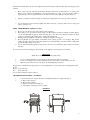
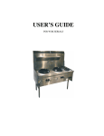
USER’S GUIDE
FOR GRIDDLE TOASTER
SPECIFICATION
NAME OF APPLIANCE
MODEL NO.
MANUFACTURED BY
CERTIFICATE NO.
SUPERTRON COMMERCIAL TWIN GRILL WITH SOLID GRILL
PLATE
HC-T-600, HC-T-900, HC-T-1200
TU’S BROS PTY LTD
77 MAIN ROAD, CLAYTON SOUTH
VIC 3169 AUSTRALIA
6235
General Description
Heavy Duty Commercial Solid Grill Plate incorporating a toasting grill area, beneath the grill plate, Manufactured in
stainless steel outer panels and mild steel inner panels with enamel finish.
Heating of the Grill Plate and Toasting Grill area is by means of cast ported burners (every 300mm wide) running front
to back beneath the solid grill plate.
The unit incorporates flame failure protection to all burners, operating a combination gas cock and flame failure valve,
with pilot ignition to the burners.
Fluing from the burner grill/toasting area is directed to the rear of the appliance into the splashback. The splashback
deflects the products of combustion from the rear walls, the outer panels are attached to a square tubular sub frame
which is rust proofed.
Exterior Panels
Sub Frame
Rear Panel
Insulation
Heating of Unit
Burner details cast bar type x
2
Flame length
Cross Light Slot
Primary Air Opening
Grill Plate
Burner Supports
Grilling or Toasting
Grease Collection Box
Drip Tray (Located in Base
of Grilling Compartment)
Secondary air to Grill
Burners
Primary air Control to Grill
Burners
Heating of the Grill Plate
Ignition to Pilot Burners
Gas cock knobs
Injectors
Regulator
304/No4/1.2mm stainless steel
25x25x2 square tube
304/No4/1.2mm stainless steel
Tombo Board
Is by means of standard Bunsen burners, cast iron with ports on either
side of the burner located beneath the grill plate running front to rear of
the unit.
2 rows of ports x 2.50mm x 7mm centers, 60 per side
430mm x 100mm width
x 2.5mm with under slung venture
Overall length 231mm from primary air entry
Ø 43mm
Cast Iron 600mm(L) / 900mm(L) /1200mm(L) x 500mm(W) x 20mm
(Thick)
Venture end supported off injector holder attached to bracket off angle
iron frame. Support for burner at end by angle iron bar.
Is by means of cast inverted grids which glow when heated and heat is
radiated to the products beneath the grid.
Beneath Grill Plate
As hot plate long x 105mm(W) x 30mm(Depth)
Induced to burners through front opening of grill compartment
Is by means of a rotating air shutter x Ø20mm with a locating hole for
centering injector into burner
Is by the burners (every 300mm) located beneath the grill plate serving
the grill compartment
Spark igniter adjacent to burner is by means of piezo press button
located on front panel or you can manual lighting at under cast plate
Indicate ‘Off’, ‘Hi’, ‘Lo’
12.7mm hexagon 25.4mm(L) x Ø11mm Nozz 15mm long with 3mm
B.S.P. thread x 6mm long
Natural Gas Maxitrol RV48m-66. App. No. 3088
2
Appliance Support
Markings
N.H.G.C.
Overall Dimensions
Height
over
splashback
Width
Depth
Depth (Body of Unit)
Height to Hob
Splashback
Weight
Gas Inlet
The unit is supplied with 4 x Ø50mm x 400mm(L) tube incorporating
adjustable feet
Supertron on splashback
Gas cock markings indicate gas flame position
Data plate on front panel
Serial No
N.H.G.C. per burner
Test Point Pressure
Lighting Instructions
NG @ 1.0 Kpa
LPG @ 2.75Kpa
Injector
N.H.G.C.
Injector
N.H.G.C.
2.05
22MJ/h
1.25
22MJ/h
1130mm
603mm (HC-T-600), 903mm (HC-T-900), 1203mm (HC-T-1200)
825mm
780mm
900mm
255mm x 82mm
40kg (HC-T-600), 80kg (HC-T-900), 120kg (HC-T-1200)
¾" – 20mm B.S.P. located 60mm in front rear of unit x 30mm in the
center of the unit x 70mm down beneath the body of the unit
INSTALLATION INSTRUCTIONS
(By Authotised Personnel Only)
this appliance should be installed by authorized persons only and must be installed in accordance with AG601, 1995
refer Section 5.12.4 Catering Equipment and all Clauses to 5.12.4.5.
GAS PIPING SYSTEM
Each Burners run front to rear.
The gas inlet to the appliance is located at the rear of the unit. The connection point is 425mm above the floor facing
down. The gas point is in the centre of the unit.
The unit is supplied with a ¾" B.S.P. regulator – the installer must supply a ¾" B.S.P. gas cock to enable isolation of
the appliance for servicing. The unit must have at least a 1" B.S.P. (25mm) pipe up to the connection point, with a
minimum pressure of no less than 1.13 kpa inlet. A minimum appliance operating pressure of no less than 0.1 kpa with
60% of the appliance operating. The installer must use a manometer to check the pressure and test for leaks.
Test points are provided off the Regulator control and off the gas cock manifold. Alternatively a burner injector may
be used off the top burner and the monometer tube placed firmly over the injector after removing the burner.
The appliance must be installed to local Health Dept. and gas fitting regulations.
For test point pressure settings refer to data plate on the appliance.
For Service: call local gas agent or retailer in your region or contact manufacturer for service information, should
appliance fail to operate correctly.
Before leaving installation instruct user on the operation of the appliance, lighting of burners etc.
OPERATING AND MAINTENACNE INSTRUCTIONS, SERVICE
These instructions must be read carefully prior to initial use and retained in a safe place.
Remove all protective covering on stainless steel panels.
GRILL PLATE BURNERS, GRILL PLATE & LOWER GRILLING COMPARTMENT (Lighting Procedure)
3
Each burner has flame failure protection. To light the main burner the pilot must be lit first. The following steps must
be taken.
1.
Press in gas cock knob and turn anti-clockwise till pilot symbol lines up with indicator on control panel.
There is a stop at this point. Light Pilot by pressing piezo button for a couple of seconds or light by match or
taper. Hold gas cock in for approximately 5-7 seconds, then release knob. The pilot should now stay on.
2.
Turn gas cock knob to indicated settings as required. The boiling burner can now be operated off the pilot.
3.
It is recommended to turn off all pilot lights at the finish of the day’s operations. This conserves energy and
reduces operating costs.
GRILL COMPARTMENT (Lighting Procedure)
1.
2.
3.
4.
5.
Press in gas cock knob to pilot symbol and stop (anti-clockwise).
Pilot is lit by a piezo press button adjacent to gas cock. Press button several times until pilot remains alight or
you can manually light the plate by match, then turn gas cock to the desired setting as indicated by flame
symbols for satisfactory flame. Pilot can be seen through viewing hole.
Warning when using grilling compartment – remember solid plate is heating also.
Pre-heat grill plate for approximately 5-10 minutes before placing products on to the plate. This preveits
sticking of meat products, then reduce flame height to prevent undue flaring of the flame while cooking. Then
pre-heat the grill toasting area as above.
It is recommended that the appliance be kept clean to prevent excess fat build up. Always empty fat collection
tray daily.
Do not use any caustic base cleaning products. Damage to the appliance could result and void warranty.
SERVICING
(Must only be carried out by Authorised Personnel)
1.
2.
3.
To remove burners tilt burner up from the front, pull forward if required for servicing.
Service of combination gas controls and burners must be carried out by an authorized person only.
When the piezo button does not work, please use manual lighting of the pilots.
For gas service call authorized local gas agent or contact manufacturer for service information should appliance fail to
operate.
Phone: (613) 9543 9577
Fax:
(613) 9544 1487
Or you call local Supertron Agent contact us.
CONVERSION INSTUCTIONS – NG TO LPG
1.
2.
Conversion must not be carried out without consulting manufacturer or agent in the region.
(a) Remove N.G. injectors
(b) Remove N.G. regulator
(c) Replace pilot injector with L.P. type
(d) Set appliance operating pressure to 2.75 kpa
DIAGRAM
4