1
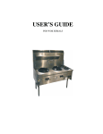
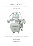
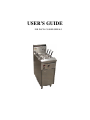
USER’S GUIDE
FOR PASTA COOKER SERIALS
SPECIFICATION
NAME OF APPLIANCE
SUPERTRON COMMERCIAL PASTA COOKER
MODEL NO.
NC-400, NC-800, NC-1200
MANUFACTURED BY
TU’S BROS PTY LTD
77 MAIN ROAD, CLAYTON SOUTH
VIC 3169 AUSTRALIA
6293
CERTIFICATE NO.
General Description
Heavy Duty Commercial Noodle/Pasta Cooker manufactured in stainless steel outer panels with stainless steel pan, in
single, double or triple units. Heating of the unit is by means of duck bill burners mounted on a cast ‘U’ shape
manifold. The burner is located beneath the fry pan. The fryer has a deep cool zone and comes equipped with complete
flame failure and over temperature cut out. The temperature of the water is thermostatically controlled. The splashback
incorporates the flue system from the combustion chamber. The flue outlet at the top of splashback deflects the
products of combustion from the rear walls. The outer panels are attached to a square sub frame which is rust proofed.
Exterior Panels
Sub Frame
Fry Pan
Rear Panel
Insulation
Heating of Unit
304-N4x1.2mm stainless steel
20x20x1.2 square tube
2.0mm stainless steel
1.2mm aluminised steel
Fibre Millboard incapsulated within a metal casing
Is by means of individual duck bill burners. The burners are mounted
onto a cast ‘U’ form manifold 40mmx40mmx3mm Square section.
Overall length 405mmx160mm centres. Duck Bill 45mm centres.
Number of Duck Bill Burners
Primary Aeration Fixed
Burner Supports
16x0.90mm orifice N.G.
16x0.65mm orifice LPG
Ø6mmx8mm up from should of thread.
Provided by 25mmx25mm angle iron welded to main frame.
Vessel Clearance
Highest sloping point of pan from top of cast manifold 300mm
Fluing
2x70x70 holes from combustion chamber into a rectangular vertical
rising flue 50mmx300mm
Overall Dimensions
Height over splashback
Width
Depth (front to back)
Working Height
Leg Height
Gas Inlet
Gas Regulator
Thermostat
Oil Drain Valve
Depth of Cool Well
Width of Cool Well
Operating Oil Level from Top
of Pan
Thermostat Capillary Location
Burner Location
Fry Pan Dimensions
Front to Back
1130mm
400mm (NC-400), 800mm (NC-800), 1200mm (NC-1200)
790mm
900mm
150mm
A ¾" B.S.P connection is provided for each pan.
276mm above floor x 90mm from left hand side
Within Nova 820 M.V. Combination Control
S.I.T. Nova 820 M.V. thermostatically operated combination control
Approval No. 4032.
Thermostat E.G.O. Model 55/130/42 Range 1100C, Approval No.
4270.
1" B.S.P (25mm)
270mm
92mm
80mm
(Bulb) 210mm from top of pan ledge x 50mm centres
400mm above floor
534mm
2
Depth
Width
Nominal
Hourly
Consumption
Test Point Pressure
Flue size
Splashback
Burner Ignition By
Floor Protection
Gas
510mm
405mm (NC-400), 805mm (NC-800), 1205mm (NC-1200)
NG:
LPG:
90MJ per Pan
85MJ per Pan
NG:
LPG:
1 KPa
2.75 KPa
From combustion chamber vertical riser into splashback outlet
420mm x50mm
250mm (H) x 90mm (W)
Hi Tension Spark Igniter incorporated within the thermostat. Pilot
light mounted adjacent to the left front duck bill burner with a fast cut
out thermocouple in conjunction with the flame failure control
Is by means of a 1.2 mm aluminized heat shield mounted off the base
of the angle iron frame. 100mm x 400mm x 460mm front to back (H
x W x D). Located against flue end of appliance.
INSTALLATION INSTRUCTIONS
(By Authotised Personnel Only)
Gas point entry is 276mm above floor and located at the left side of the unit. A 20mm 3/4" BSP regulator is supplied
with each pan.
The installer is to supply and fit an isolating gas cock to the appliance for ease of servicing the control system. N.B.
Double and Triple units have separate inlet to each control and must have a separate gas cock.
The installer must install the appliance to AG601, 1995 Sections 5-12-4.5 and in accordance with local gas and water
regulations. Clearances form combustible walls sides – left and right 50mm. Rear wall 50mm and must be installed on
a fire proof base. Unit may be installed against fire proof walls. Refer installer instructions for special instructions for
this type of installation.
ADDENDA
“The installer must install the appliance to AG601, 1995 Section 5.12.4 and in accordance to local regulations,
attention must be give to Section 5.12.4.4 and 5.12.4.5.
5.12.4.6 Commercial catering equipment on combustible surface, where equipment is installed on a combustible
surface it shall be protected by fire resistant material.
Fire resistant material specifications where appliances are to be installed in non combustible area, the installer must
refer to AG601 and ensure the following side walls and bare walls have materials to the specifications referring to
standards A-S 1530.1 to be deemed not combustible and A-S 1530.3 have a zero (0) index for all of the following:
1.
2.
3.
4.
Ignitability
Spread of flame
Heat evolved
Smoke developed
N.B.
The thermal resistance not less than 0.05 M20 c/w but in no instance shall the material be of a thickness less
than 6mm.”
All models have a 20mm 3/4" BSP socket gas point or compression inlet.
The appliance must be installed as set out in the specifications i.e. Natural gas operating test point pressure 1 KPa.
Before leaving installation, check all gas and water fittings for leaks, and instruct operator in lighting and use of
appliance. N.B. This appliance must always be mounted on 320mm legs as supplied.
If unit fails to operate, please contact local distributor or call manufacturer on Phone: (613) 9543 9577
9544 1487.
Fax: (613)
3
OPERATING AND MAINTENANCE INSTRUCTIONS, SERVICE
The pan features a centre cool zone and crumb trap. A drain-off valve is provided.
Heating of the fryer is by means of duck bill burners of high quality material with ports drawing in secondary air
through the centre.
The unit incorporates complete flame failure, safety and temperature control by a thermostat operation. A manual reset
over temperature device is provided mounted on the frame adjacent to the burner, that should the thermostat fail, the
gas is automatically turned off to the pilot system.
Lighting Procedure for NG & LPG Units:
1.
Interior of pan to contain enough water to cover the thermostat bulb, to prevent overheating on burner
ignition.
2.
Turn thermostat to the OFF position.
3.
Open main gas cock.
4.
Press knob & turn anti-clockwise to lighting position (marked with a yellow embossing) and light pilot
head adjacent to the burner. Press in piezo button for spark to light pilot.
Note: On new installations this procedure may need to be repeated 2 or 3 times to allow dispersing of
air trapped in gas line to unit. Normal time - approx. 15 seconds.
5.
Press in knob and turn slowly to high flame position for fast heat up, and then back to the temperature
required by setting of thermostat on control panel.
6.
The main burner can now be turned either completely on or off by means of the thermostat knob.
Note:
7.
Pilot burner will not be affected.
If piezo lighting is not work, manual light can be used.
Turning OFF Procedure:
1.
Turn thermostat to off. This closes the gas-way to the burner and also closes off the gas-way to the pilot.
Turn main valve off.
2.
The gas-way remains locked down by means of an Interlock device.
Thermostat Operation
The thermostat is adjusted so that when the temperature of the water reaches the thermostat dial setting the burner
shuts off automatically and comes on again upon cooling, to maintain the temperature required.
Note:
For normal operation the thermostat dial can be used for the ON or OFF of the gas supply to the burner.
Turn off at gas cock on appliance when appliance not required for use for long periods.
Pan Draining
A drain valve is located at the base of the cool zone and opening and closing of the valve is by means of a handle
located on the front of the units, behind access door.
SERVICING
(Must only be carried out by Authorised Personnel)
Thermostat Re-Calibration – for NG & LPG
1.
Set temperature to 1490C.
2.
Remove thermostat dial from control by simply pulling forward.
4
3.
Adjust thermostat within control.
4.
Contact Manufacturer for Servicing of Combination Control and Thermostat if unable to set controls.
Otherwise warranty may be void. Phone (03) 9543 9577 or Fax (03) 9544 1487 for assistance.
DIAGRAM
5