1
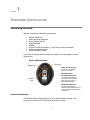
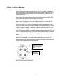
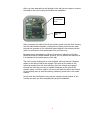
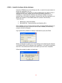
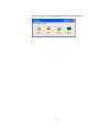
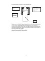
BioLock® Users Guide Version 1.0 Bio Recognition Systems Pty Ltd Unit 11, Building F, 16 Mars Rd, Lane Cove NSW, Australia 2066 Ph: +61 2 9882-8600 Fax: +61 2 9427-2503 1 Disclaimer BIO RECOGNITION SYSTEMS PTY LTD LICENCES THE SOFTWARE AND DOCUMENTATION PRODUCT TO YOU, OR YOUR COMPANY, SOLELY ON AN “AS IS” BASIS AND SOLELY IN ACCORDANCE WITH THE TERMS AND CONDITIONS OF THE ACCOMPANYING LICENCE AGREEMENT. BIO RECOGNITION SYSTEMS PTY LTD MAKES NO OTHER WARRANTIES WHATSOEVER EITHER EXPRESS OR IMPLIED, REGARDING THE SOFTWARE OR THE CONTENT OF THE DOCUMENTATION. BIO RECOGNITION SYSTEMS PTY LTD HEREBY EXPRESSLY STATES AND YOU OR YOUR COMPANY ACKNOWLEDGES THAT BIO RECOGNITION SYSTEMS PTY LTD DOES NOT MAKE ANY WARRANTIES, INCLUDING, FOR EXAMPLE, WITH RESPECT TO MERCHANTABILITY, TITLE, OR FITNESS FOR ANY PARTICULAR PURPOSE. Trademarks Copyright BioLock®, BioKey® are all registered trademarks of Bio Recognition Systems Pty Ltd. Microsoft, Windows NT and MS-DOS are registered trademarks of Microsoft Corporation. Copyright © 2005 Bio Recognition Systems Pty Ltd. All rights reserved. Reproduction or transmittal of this publication, or portions of the publication, is prohibited without the express prior and written consent of the publisher. Photocopying and distribution within your organisation is permitted. Patents & Technology BioLock® is protected by numerous patents pending and design registrations involving its technology. For further information please contact us. Bio Recognition Systems Pty Ltd Unit 11, Building F, 16 Mars Rd, Lane Cove NSW, Australia 2066 AUSTRALIA. Ph: +61 2 9882-8600 Fax: +61 2 9427-2503 BioLock® Getting Started Manual. Version 1.0 Last Updated: 14 January 2006 2 CONTENTS Disclaimer ........................................................................................... 2 Trademarks......................................................................................... 2 Copyright............................................................................................ 2 Patents & Technology .......................................................................... 2 CONTENTS ......................................................................................... 3 BIO RECOGNITION SYSTEMS PTY LTD SERVICES ............................. 5 COMPANY INFORMATION ............................................................................. 5 CONTACT INFORMATION .............................................................................. 5 HARDWARE SUPPORT ................................................................................. 6 Warranty Support ................................................................................ 6 The Bio Recognition Systems Pty Ltd Web Site....................................... 6 Regulatory Compliance......................................................................... 6 International Biometrics Standards Compliance ...................................... 7 INTRODUCTION ................................................................................. 8 HARDWARE INSTALLATION............................................................... 9 INSTALLING BIOLOCK® .............................................................................. 9 HARDWARE PROGRAMMING ........................................................... 17 PROGRAMMING BIOLOCK® ......................................................................... 17 ENTERING ADMIN MODE ........................................................................... 17 CONNECTING THE SECURE RELAY BOARD ....................................................... 17 PROGRAMMING THE BIOLOCK® RELAY ON TIME .............................................. 17 TESTING THE RELAY ON-TIME DURATION ......... ERROR! BOOKMARK NOT DEFINED. ADDING USERS ....................................................................................... 18 DELETING USERS..................................................................................... 18 DELETING ALL USERS ............................................................................... 18 VERIFYING USERS .................................................................................... 18 FACTORY DEFAULT ................................................................................... 18 USING BIOLOCK .............................................................................. 19 Centering the Core ............................................................................ 20 Identification Errors ........................................................................... 20 False Acceptance ............................................................................... 20 False Rejection .................................................................................. 20 GLOSSARY........................................................................................ 23 USER COMMENTS............................................................................. 25 3 Chapter 1 BIO RECOGNITION SYSTEMS PTY LTD SERVICES Bio Recognition Systems Pty Ltd are pleased that you have chosen ‘BioLock®’ our New Keyless Finger Print Unit system - to help you to run your business/office or home more efficiently. Our aim has been to develop the most technologically advanced BioMetric Products at realistic prices. Company Information Bio Recognition Systems Pty Ltd (BRS) is a Research, Development and BioMetrics Manufacturer based in Sydney NSW Australia. Since early 2000 we have been developing and supporting our range of BioMetric Security and Time Management software and hardware solutions. This latest product BioLock® is a fully embedded finger print device that incorporates all of the features of the more expensive competitive units along with many additional features. Contact Information You can contact Bio Recognition Systems (BRS) in any of the following ways: Address Phone FAX Email World Wide Web Unit 11, Building F, 16 Mars Rd, Lane Cove NSW 2066 AUSTRALIA. +612 9882-8600 +612 9427-2503 [email protected] [email protected] http://www.brsgrp.com 5 Hardware Support Bio Recognition Systems Pty Ltd (BRS) currently provides hardware support between the hours of 9am and 5pm (EST), Monday through Friday. In addition, we provide annual hardware support programs. Warranty Support BioLock® is warranted for a period of 12 months, within this period if the unit becomes defective due to workmanship or failure of the electronic components, Bio Recognition Systems Pty Ltd at its full discretion will replace, repair or offer an alternative product. Any Bio Recognition Systems Pty Ltd product which has any serial number labels, any logos or silk-screen printing removed in any way from its original placement will automatically invalidate the warranty. At no time will onsite warranty be offered unless a separate onsite warranty agreement has been entered into and paid for by the customer. All warranties require that the unit be return back to Bio Recognition Systems Pty Ltd for servicing or repaired through an authorised distributor of Bio Recognition Systems Pty Ltd. Finger Sensors, or parts that can suffer from wear & tear are not covered under this warranty. Finger Sensors, Power supplies and batteries supplied with Bio Recognition Systems Pty Ltd products are warranted for 3 months only. The Bio Recognition Systems Pty Ltd Web Site The Bio Recognition System’s web site can be found at http://www.brsgrp.com Here you will find information about BioLock® and a Customer Support section. The Customer Support section contains downloadable documents, technical articles and product firmware updates. Regulatory Compliance The product has been tested and has compliance to the following standards: a) b) c) d) e) f) European low voltage directive, ie. EN60950 European EMC directive, ie. EN50082 Australian New Zealand EMC requirements, AS3548. Level 2 US FCC Part 15J Emission Standard CE CISPR22 6 International Biometrics Standards Compliance The product has been tested and has compliance to the following standards: BioAPI Compliant (ANSI / INCITS 358-2002) CBEFF - Common Biometric Exchange File Format Compliant (NISTIR 6529-2001) 7 Chapter 2 INTRODUCTION BioLock® is the new Breed of Biometric hardware that has the ability to scan a human finger print even if the finger print is non-existent. It does this by using technology known as non-invasive Radio Frequency scanning. It allows the sensor to look under the skin to see the true fingerprint. The unit is a fully functional Finger Access unit or data acquisition device for gathering data on movement of employees. Incorporating standard 10BaseT communications technology BioLock ® provides users the ability to run long distances including over the internet removing distance restrictions. BioLock can be installed outdoors as it is weather rated to IP65 which means it can handle water jets of low to medium pressure directly without the concerns of damage or ingress into electronic circuitry. Being weather resistant BioLock is ideal for outdoor access control gates, bollards, parking lots or any application requiring either a clean or dirty environment. BioLock will also resist all dust and small particles and is rated to withstand this ingression indefinitely. 8 Chapter 3 HARDWARE INSTALLATION Installing BioLock® BioLock® includes the following components: BioLock Metal Unit Metal Mounting Backplate Power Supply (9V DC) Cable assembly CDROM Secure I/O PCB & Enclosure ( If Security product purchased) Screw and assembly pack Quick Installation Guide If any item is missing please contact the supplier who can replace missing components. Device LED Indicators Red Led Green Led Power On Green Led The Green Led indicates power to the device Identify Success Enrolment Yellow Led The Yellow Led indicates a successful scan has taken place, also it is used for Enrolment assistance. Yellow Led Identity Fail Red Led The Red Led indicates a failed scan has taken place and Is also used for assistance with enrolments. Power Requirements The BioLock Device requires power from an external power supply. The product ships with a 9V DC Plug Pack style power supply. 9 STEP 1 – Location & Mounting Find the best location for the mounting of the metal backplate – shown below. Note it is important that the surface be flat, if it is not then it is advised to pack out the bracket with washers or material to provide a flat base. The unit will not seal, and the tamper switch will not sit accurately if the bracket is twisted in any way. Drill a large hole in the mounting location to enable passing the BioLock II Cable (BRS-819-29) RJ45 socket through the opening. Attach the RJ-45 socket on the cable assembly supplied to a valid CAT5 network via an CAT5 Ethernet cable. Attach the Power + & - wires to the adaptor supplied. Terminate all wires used and unused in the screw strips provided to eliminate shorting or failures. The 8 Pin White connector on the cable must be passed through the 7mm hole via the rear or back of the metal backplate closest to the wall and in doing the grommet placed on the cable must be tightly inserted into the 7mm hole. Leave ample cable hanging out of the hole whilst mounting so that you can manipulate the front housing when plugging the cable in. See Diagram below. Attach the wall bracket to the wall or substrate surface via the use of 4 Countersunk screws. It is important that countersunk screws are used as this will guarantee a good fit and weather protection when the screws touch the bottom of the rebated holes when tightened. Front Housing screw locking engagement keys Cable pass through hole FRONT VIEW OF METAL BRACKET 10 After you have attached the wall bracket to the wall you are ready to connect the cable to the front housing and finalise the installation. 8 Way Cable is connected here Outer rim seal After connecting the cable to the 8 way socket, gentle bring the front housing and the metal bracket together, making sure to gently push back the cable through the grommet as you close both parts together. Also ensure that the outer rim seal has no wires underneath it as you close it up. Be aware during manufacturing Silicon oil lubricant is placed on the Outer Gasket Rim Seal for added weather proofing. Do not remove this lubricant as it is important to the performance of the seal. The front housing is designed to come together with the bracket 5 degrees slightly to the left off centre and engage 4 key slots by the heads of the screws protruding from the front housing. Once the screws are engaged through the holes the unit may be rotated 5 degrees to the right to the position where no further rotation can occur and when the slot in the bottom of the housing lines up with the security positioning screw hole in the metal bracket. At this point the Hex Security screw can be inserted into the bottom of the housing and then you have completed the physical installation. 11 STEP 2 – Configure Network Address & Settings You must now configure the BioLock device and give it a network address. **NOTE** you must be on the same subnet as 192.168.0.x to be able to do Please ensure you have configured your PC correctly. Open up Internet Explorer and type in the address bar http://192.168.0.210 The BioLock Home Page window should appear. Select Network to Change the IP and Address Settings of the BioLock Select Sensor Diagnostics to View Images after you have installed software and hardware Select Led/Buzzer to Manually Turn on Led’s and Sound Buzzer Select Tamper to Ensure that the Tamper Switch is Functioning Correctly 12 STEP 3 – Install & Configure BioKey Software Insert the CDROM and run the BioKey.exe file, or wait for the auto starter to launch the application for you. Install the software to a location on your computer that you wish to have it operate and run from. Please note the BioLock software requires no installation or dependencies therefore the software installer is only just copying files to a location you specify. Copies of the two files required to run BioKey are located on the CDROM under the \Source Files directory. These files are: BioKey.exe ( Main Executable) BioLockAPI.dll ( Communications and Matching DLL) Once installed run the Program from the Start, Programs BioKey Directory or from the desktop where a shortcut has also been installed, the following program window will appear. Login password by default on startup is left blank so just press Enter BioKey is designed to assist you in first starting and configuring the software via a Wizard which will first appear after installation. You must first configure the Unit in the software and add a user before you can enrol a template. Follow the prompts to add a unit and user. 13 The wizard will now prompt you to enter the unit details Enter a Unit Name, ID and the correct IP address you have assigned. You may now enrol a user and template. Now you are required to enrol a user template. 14 Once a Unit and User are Configured the Main Form will show. 15 STEP 4 – Install Optional Secure I/O Configuration and installation of Secure I/O PCB Once you select OK The system is now ready to operate. Any person enrolled who touches the BioLock device, as long as they have rights then the Secure Relay Board will operate. 16 Chapter 4 HARDWARE PROGRAMMING Programming BioLock® Upon powering up BioLock® the unit will flash the Red (Fail) & Green (Verify) LED’s. This is acknowledging that there are no users currently enrolled in the device. The unit will now require user and system programming. Go to Step 3 of the guide above. Entering Admin Mode Admin mode is entered via the following method. Power on the unit. Red and Green Leds at the top will flash indicating no users are enrolled. Place any Administrators finger on the unit and leave it on the sensor for 5 seconds. Quickly remove finger from sensor You are now in Administrator Mode and BioLock® is ready to have additional user templates enrolled. Connecting the Secure Relay Board The Secure Relay Boards become known to the BioLock units automatically as soon as they are connected to the RS485 Data wires out of the BioLock unit. No further configuration is required. Programming The BioLock® Relay On Time This function is performed within the BioKey software 17 Adding Users Administrator places their finger on the reader for 3 seconds Remove finger from sensor Next step is to enrol the finger of User 1. This is done by placing the top section of the finger above the first joint evenly across the finger sensor. The Enrol procedure requires fingers to be placed three times for a successful enrolment. Place the finger for the first time on the sensor, the RED and GREEN Leds at the top will light, do not remove your finger until the two Leds turn off. Place your finger for the second time again waiting for both Leds to go out before removing your finger. Place your finger for the final time and wait for the Leds to go out before removing your finger. If the finger was placed in the same position each time within parameters the GREEN led will come on and the RED will remain off indicating ENROL OK. Deleting Users Can only be achieved via the BioKey software Deleting All Users Can only be done from BioKey Software Verifying Users Verifying is a test for a recently enrolled user The user only needs to place their finger on the sensor firmly and flat If accepted the reader will light the green verify success led If failed the reader will light the red fail led Factory Default You may return the BioLock device to the original factory default settings by doing the following; Remove the front housing from the bracket Hold down the tamper switch Whilst holding the tamper switch quickly touch the sensor 3 times within 2 seconds You will now have defaulted the unit back to factory settings with IP Address now set to 192.168.0.210 18 Chapter 5 USING BIOLOCK To ensure correct operation of BioLock® it is imperative that the guidelines below be followed without question or variation. A fingerprint is a characteristic pattern that is unique to the individual person bearing it. Although fingerprint patterns vary widely from type to type, each fingerprint has a small central area around which the remainder of the pattern is distributed. This central area is the “core” of the fingerprint. Typically, this core is opposite the point that the fingernail emerges from the cuticle. While the matching algorithm of the BioLock system is quite tolerant to nonoptimum finger placement, centering the core on the sensor will give the best possible performance. Find your fingerprint cores and verify that the core location of your fingerprints is approximately as described. Most fingers will follow this general rule. If your core location is very different, adjust your finger placement accordingly. Capture the full area of the fingerprint by contacting the sensor surface with the finger placed flat on the sensor, as opposed to presenting only the tip of the finger. The fingertip alone contains insufficient image data for a high-quality fingerprint. The ridges in this area are mostly parallel lines, with few distinct minutiae from which to construct an identification template. It is unlikely that the image management algorithm will actually permit enrollment, but if it does, such a feature-poor environment can lead to False Acceptance errors. Lay the finger down flat, lightly but firmly on the sensor make sure that the finger is placed perpendicular to the sensor. This results in minimal distortion of the skin. If the finger is pulled or pushed left or right, forward or back, the image is distorted and the fingerprint quality is reduced. Note: Do not roll the finger as you might when taking a traditional ink-andpaper image! Keep the finger flat and motionless against the sensor detection surface during the imaging process. The BioLock matching algorithm can tolerate non-optimum entry angles up to ±15°, in addition vertical displacement ±5mm and laterally ±7mm but the performance of the matching algorithm may be affected by this misalignment. 19 Centering the Core In some cases, if the core of the fingerprint is not placed correctly, the software may incorrectly reject a registered user. In this case, simply lift the finger and replace it on the sensor with the core more closely centered on the sensor. The matching process should then be performed correctly. During enrollment, you will be asked to lift and replace your finger on the sensor several times. The performance of the matcher can be improved by taking care to place the finger in slightly different locations on the sensor for each one of the enrollment placements. This gives the matcher the opportunity to create a composite image of the finger, including more area than can be seen in a single view. Identification Errors The biometric industry generally uses two principal criteria to assess the performance of a given identification system. These are: False Acceptance Rate (FAR) – The FAR is the measurement of the probability that a biometric system will incorrectly identify an individual. Statistically, the chance that two individuals will have identical fingerprints is about one septillion to one. False Rejection Rate (FRR) – The FRR is the measurement of the probability that a biometric system will fail to identify an individual who is properly enrolled. False Acceptance In biometric systems in general, false acceptance errors are the less frequent of the two problems. In the case of the BioLock sensor, false acceptance is extremely rare, and so far always the result of a bad enrollment. False Rejection For various reasons, false rejection errors are much more frequently encountered in biometric systems. In the case of the BioLock sensor, false rejection sometimes occurs when the core of the fingerprint is not present or is grossly misplaced on the sensor detection surface. Lift the finger, then replace it with more care in positioning to solve this problem. Other causes of false rejection errors might be contamination of the sensor surface. In addition, physiological processes such as dermatitis, disease, aging, and calluses can obscure fingerprints. They can be mechanically damaged – worn smooth, contaminated by dirt, etched by chemicals, or even burned or scarred. The reduction of skin tone and elasticity due to collagen loss in the aging process also contributes to a general deterioration of the skin. Most of these adverse factors do not greatly affect the performance of the BioLock sensor because rather than interacting with the outer layer of the skin 20 it operates below the surface, in the subdermal layer. Internal Sensor Array Outer sensor array, silver finish approx 3 mm wide Fingerprint Core under nail cuticle Finger Please ensure that the finger is placed across the two opposite sides of the sensor, making sure that the fingerprint core is kept as centered as possible. AT all times the finger must be flat as possible, this ensures that the RF signal is correctly directed into the finger to provide a good finger image. A good firm press MUST be provided. 21 Appendix A GLOSSARY For future use 23 USER COMMENTS Bio Recognition Systems Pty Ltd (BRS) would welcome your comments and suggestions about our manuals. Please send your comments to the below address, fax or email: Bio Recognition Systems Pty Ltd Unit 11, Building F, 16 Mars Rd Lane Cove NSW AUSTRALIA 2066 Phone: +612 9882-8600 Fax: +612 9427-2503 Email: [email protected] BioLock® Getting Started Version 1.0.0 Company: Address: Phone: Fax: Excellent Good Completeness Readability Format Accuracy Examples Usefulness In what ways could this manual be improved? 25 Fair Poor