1
English
Operating instructions
Groundwater Datalogger
OTT ecoLog 800
These operating instructions (version "03-0613") cover the OTT ecoLog 800
software versions
OTT ecoLog 800 firmware: V 1.00.0 and later
OTT Water Logger Operating Program: V 1.65.0 and later
The OTT ecoLog 800 firmware can be found in the "Advanced operation" mode,
"OTT ecoLog 800" window of the operating program. The version of the operating program can be found via the "Info" function in the "Help" menu.
We reserve the right to make technical changes and improvements without notice.
Table of contents
1 Scope of supply
5
2 Order numbers
5
3 Basic safety information
7
4 Introduction
8
5 Installing, checking, and replacing the batteries
5.1 Power supply using lithium batteries
5.2 Power supply using alkaline batteries
10
11
15
6 Inserting a SIM card
17
7 If required: Connecting an external radio antenna
18
8 Installing the OTT ecoLog 800 unit
19
8.1 Installing the unit into 2" observation wells,
top cap with cut-out
8.2 Installing the unit into 3", 4" or 6" observation wells,
top cap with cut-out for adapter plate
8.3 Installing the unit into observation wells of 3" in diameter and
above, top cap without cut-out for adapter plate
8.4 Installing the unit into observation wells of 3" in diameter and
above, without top cap, universal installation
9 Setting OTT ecoLog 800 operating parameters
9.1
9.2
9.3
9.4
9.5
9.6
Installing the OTT Water Logger Operating Program
Establishing the PC/OTT ecoLog 800 communication link (on site)
Establishing the communication link from remote
Setting OTT ecoLog 800 operating parameters
Saving/loading an OTT ecoLog 800 configuration
Importing/exporting an OTT ecoLog 800 configuration
20
21
23
25
26
26
26
27
28
32
32
10 Determining and displaying instantaneous values (observer function)
34
11 Reading data
36
12 Exporting data
37
13 Displaying data
38
14 Protecting the OTT ecoLog 800 unit and the OTT Water Logger
Operating Program using a password
39
15 Setting date and time
41
16 Erasing the data memory
42
17 Updating the OTT ecoLog 800 firmware
42
18 Maintenance work
43
18.1
18.2
18.3
18.4
Cleaning the pressure probe
Replacing the desiccant capsules
Checking/replacing the batteries
Calibrating the conductivity sensor
43
44
45
45
3
4
19 Error messages
47
20 Troubleshooting/fault correction
47
21 Repair
49
22 Notes about the disposal of used units
49
23 Technical data
50
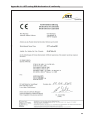
Appendix A – OTT ecoLog 800 declaration of conformity
53
1 Scope of supply
OTT ecoLog 800
– 1 groundwater datalogger consisting of a communication unit with built-in
GSM/GPRS modem, pressure probe cable with pressure compensation
capillary and Kevlar core for longitudinal stabilization, 2 desiccant capsules;
pressure probe with integrated conductivity sensor and datalogger
– 1 lithium battery, DD type (26 Ah); or
1 lithium battery, D type (13 Ah); or
2 alkaline batteries (1.5 V), LR14 · AM-2 · MN 1400 · C type, incl. battery holder;
– 1 operating instructions
– 1 factory acceptance test (FAT) certificate
2 Order numbers
OTT ecoLog 800
Accessories *
Groundwater datalogger
– incl. lithium battery, DD type (26 Ah); or
incl. lithium battery, D type (13 Ah); or
incl. 2 x 1.5 V alkaline type (C cell)
Required ordering information
– Measuring range: 0 … 4 / 10 / 20 / 40 / 100 m
– System length:
2 … 200 m (±1 % ±5 cm)
Adapter plates
for OTT top caps with cut-out
– 3"
– 4"
– 4,5"
– 5"
– 6"
55.447.001.9.0
55.447.002.9.0
55.447.005.9.0
55.446.022.9.2
55.446.023.9.2
on request
on request
55.446.026.9.2
Universal suspension bracket
for top caps from 3" upwards, without cut-out
as well as for universal installation
55.446.021.9.2
"OTT Water Logger Software CD-ROM"
OTT Water Logger Operating Program for PC, and
OTT ecoLog 800 operating instructions (PDF file)
56.572.002.9.7
External radio antenna
cable length: 0.5 m
cable length: 1.0 m
cable length: 1.5 m
cable length: 5.0 m
97.980.062.9.5
97.980.061.9.5
97.980.060.9.5
97.980.101.9.5
5-sided key
for locking OTT top caps
20.250.095.4.1
Optical OTT DuoLink reading head
55.520.017.4.2
Optical reading head OTT IrDA link USB
55.520.026.9.2
Calibration container
55.445.025.9.2
* Additional accessories – e.g. plastic top caps, top caps with external or internal radio antenna on request.
5
Spare parts/
Lithium battery, DD type (26 Ah)
97.800.011.9.5
Lithium battery, D type (13 Ah)
97.800.009.9.5
Battery holder for
2 alkaline batteries (1.5 V), batteries not included
55.446.020.9.2
Alkalinebatteries, 2x
LR14 · AM-2 · MN 1400 · C type
96.800.003.9.5
Desiccant capsules
2x in one aluminum bag
97.100.296.9.5
Consumables
Conductivity calibration solution
–
0,1 mS/cm; 1000 ml
–
0,5 mS/cm; 946 ml
– 1,412 mS/cm; 1000 ml
– 12,856 mS/cm; 946 ml
– 47,6 mS/cm; 1000 ml
6
55.495.350.9.5
55.495.351.9.5
55.495.352.9.5
55.495.353.9.5
55.495.354.9.5
3 Basic safety information
Read these operating instructions before using the OTT ecoLog 800 for the first
time! Become completely familiar with the installation and operation of the
OTT ecoLog 800 and its accessories! Keep these operating instructions for later
reference.
The OTT ecoLog 800 is designed to measure groundwater levels, the water
temperature and the specific conductivity of the groundwater and to transmit
these measured values through a GSM cellular network.
Only use the OTT ecoLog 800 as described in these operating instructions!
For further information ➝ refer to Chapter 4, "Introduction".
Please note all safety and warning information given within the individual work
steps. All safety and warning information given in these operating instructions
are marked by the following adjacent warning signals:
– Black warning triangle ➝ warning of potential damage to the unit,
reduced functionality and particularly noteworthy points.
– Black warning triangle with yellow background ➝ there is a
health hazard! Detailed information on the hazard including information on
how to prevent the hazard and possible consequences of non-observance.
Ensure the electrical, mechanical, and climatic specifications listed in the
technical data are adhered to.
For further information ➝ refer to Chapter 23, "Technical data".
Handle the pressure probe cable with care. Do not kink the cable or pull it
across sharp edges!
Do not make any changes or retrofits to the OTT ecoLog 800! If changes or
retrofits are made, all guarantee claims are voided.
Have a faulty OTT ecoLog 800 inspected and repaired by our repair center.
On no account carry out repairs yourself!
For further information ➝ refer to Chapter 21, "Repair".
After putting the unit out of service, properly dispose of the OTT ecoLog 800.
On no account put the OTT ecoLog 800 into the normal domestic waste.
For further information ➝ refer to Chapter 22, "Note about the disposal of
used units".
CAUTION
Risk of burns! Hot device surface at higher ambient temperatures!
The metal parts of OTT ecoLog 800 device surface can get very hot at
higher ambient temperatures*. This may lead to burns.
Use protection gloves during installation and maintenance at higher
ambient temperatures*!
* > approx. 60 °C / 140 °F
Federal Communications Commission (FCC) Approval
Note: This equipment has been tested and found to comply with the limits for a
Class A digital device, pursuant to part 15 of the FCC Rules. These limits are
designed to provide reasonable protection against harmful interference when the
equipment is operated in a commercial environment. This equipment generates,
uses, and can radiate radio frequency energy and, if not installed and used in
accordance with the instruction manual, may cause harmful interference to radio
communications. Operation of this equipment in a residential area is likely to
cause harmful interference in which case the user will berequired to correct the
interference at his own expense.
Industry Canada Approval
This Class A digital apparatus complies with Canadian ICES-003.
Cet appareil numérique de la classe A est conforme à la norme NMB-003 du
Canada.
7
4 Introduction
The OTT ecoLog 800 groundwater datalogger is designed to precisely measure
and store groundwater levels and temperatures, as well as the specific electrical
conductivity of the groundwater and to transmit these measured values through a
GSM cellular network. The OTT ecoLog 800 also calculates the salinity and a TDS
value (Total Dissolved Solids) based on the specific conductivity.
The pressure probe equipped with a relative pressure probe cell uses the hydrostatic
pressure of the water column to determine the water level. As a reference, a pressure compensation capillary in the pressure probe cable provides the measuring
cell with the current ambient air pressure. Erroneous measurement results due to
atmospheric air pressure fluctuations are thus eliminated. The OTT ecoLog 800
measures the specific electrical conductivity using a 4-electrode conductivity sensor
with integrated temperature sensor. The measurement electrodes are made of
graphite.
The temperature compensation process for the conductivity measurement and the
reference temperature used can be chosen as well as the calculation method for
the salinity.
The OTT ecoLog 800 is available in five measuring ranges:
0
0
0
0
0
…
…
…
…
…
4 m water column (0 ... 0.4 bar)
10 m water column (0 ... 1 bar)
20 m water column (0 ... 2 bar)
40 m water column (0 ... 4 bar)
100 m water column (0 ... 10 bar)
Based on a reference value that is input during startup, the OTT ecoLog 800
default setting provides measurement results in the form of depth values. Alternatively, levels or pressure values are possible. The measurement intervals (sample
intervals) can be preselected as necessary.
The operating parameters are set using the "OTT Water Logger Operating Program" PC software. This software allows the system to be conveniently and flexibly
tailored to a wide range of measurement requirements of a station. The software
can be set to provide a basic or an advanced user interface. The basic user interface allows all settings to be adjusted within a single program window. In the
advanced user interface, the sample interval can be controlled e.g. by means of
limit events. The software also supports the execution of pumping tests.
The stored measured values are made available through an infrared interface
(IrDA) for wireless readout using PC on which the OTT Water Logger Operating
Program is executed.
The OTT ecoLog 800 includes a GSM modem with SMA antenna connector that is
used for remote data transfer and remote parameterizing through the GSM cellular network (GSM = Global System for Mobile communications). The remote data
transfer can be optionally carried out by SMS text messages or using the packet
oriented mobile radio transmission service GPRS (General Packet Radio Service).
If necessary – e.g. when the signal strength of the cellular network is low at the
installation site – the factory installed radio antenna may be replaced by an external one.
The OTT ecoLog 800 is installed by simply hanging it into observation wells of 2"
in diameter and above. For this purpose, various adapters/suspension brackets
are available as accessories. For power supply, three options are available:
lithium battery, DD type, 26 Ah capacity; lithium battery, D type, 13 Ah capacity;
or commercial alkaline batteries (incl. dedicated battery holder). When using the
DD type lithium battery, battery lifetime is (depending on additional parameters)
at least 10 years, taking into account one single remote data transfer per day.
The communication unit of the OTT ecoLog 800 can withstand temporary flooding
(for details, refer to Chapter 23, "Technical data").
8
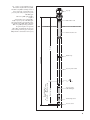
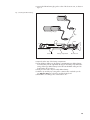
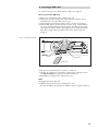
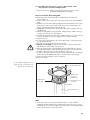
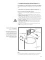
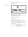
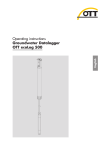
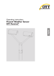
Fig. 1: Setup of a groundwater measurement station using the OTT ecoLog 800.
The OTT ecoLog 800 essentially consists of
three components: communication unit,
pressure probe cable, and pressure probe
with datalogger.
Top cap
OTT ecoLog 800 system length =
length of
communication unit + cable length +
length of pressure probe with datalogger.
(The system length is required when ordering an OTT ecoLog 800. When setting the
OTT ecoLog 800 operating parameters,
the system length is not required.)
Observation well
(The rubber stop attached to the pressure
probe cable prevents the pipe casing from
falling when the communication unit is open.)
Depth
Communication unit
System length
Rubber stop
Measuring range
Measuring ranges:
0 … 4 m, 0 … 10 m, 0 … 20 m,
0 … 40 m, 0 … 100 m Water column
Pressure probe cable
Pressure probe
with datalogger
Conductivity sensor
Pressure sensor
9
5 Installing, checking, and replacing batteries
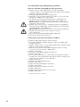
WARNING
Improper handling of batteries involves fire or explosion hazard!
Only use the battery types specified (no rechargeable types).
Always use brand-new batteries. Do not mix used and new batteries.
Do not mix batteries from different manufacturers
Do not charge the batteries!
Avoid short circuits!
Avoid mechanical damage!
Do not open batteries!
Do not expose batteries to fire or to temperatures above 100 °C!
Do not solder on the batteries!
Properly dispose of exhausted batteries. Do not put them into domestic waste.
Suitable battery types
Lithium battery, DD type (26 Ah), (use OTT accessories only); or
Lithium battery, D type (13 Ah), (use OTT accessories only); or
2 alkaline batteries (1.5 V), LR14 · AM-2 · MN 1400 · C type.
For using the alkaline batteries, a dedicated battery holder is required.
Battery lifetimes
The values mentioned below apply to the following conditions: sample interval –
1 hour; one single remote data transfer per day; system length – 50 m.
Lithium battery, DD type : at least 10 years,
Lithium battery, D type :
at least 5 years,
Alkaline batteries:
at least 1 year (high quality battery types).
Notes
The OTT ecoLog 800 starts measuring after inserting the batteries (there is no
ON/OFF switch).
If the OTT ecoLog 800 is to be shut off ➝ remove the batteries. This will pre-
vent the batteries from draining prematurely and will stop any recording of
unusable measurements.
When transporting the OTT ecoLog 800 ➝ remove the batteries. This will prevent the batteries from draining prematurely and will stop any recording of
unusable measurements.
When bringing the unit back into operation it takes up to –7 minutes– before
the OTT ecoLog 800 starts measuring again (during this time, the OTT ecoLog
800 re-initializes its database).
10
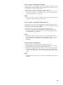
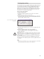
Check the battery voltage as follows
Establish the PC/OTT ecoLog 800 communication link,
refer to Chapters 9.2 or 9.3.
Select the "OTT ecoLog 800" menu, "View Instantaneous values" function 1) ➝
The OTT ecoLog 800 starts an instantaneous value measurement ➝ The
"Observer" window indicates the current battery voltage and the energy drawn
from the batteries so far in Ah.
– Alkaline batteries: Criterion for replacing the batteries:
Battery voltage lower than about 1.9 V
➝ Replace the batteries.
– Lithium batteries: Criterion for replacing the batteries: Ah drawn
Lithium battery, DD type: > approx. 20 Ah
Lithium battery, D type :
> approx. 10 Ah
➝ Replace the batteries.
(For technical reasons, the battery voltage displayed cannot not be used as a
criterion for replacing lithium batteries.)
Click on the "Exit" button.
Close the operating program.
1)
With suitable settings (Menu "File", function "Options"), the operating program starts with the
"Observer" window.
Notes
The OTT ecoLog 800 stores the measured values in a non-volatile memory.
There is no loss of data when changing batteries.
This also applies to storage without batteries for a long period.
If replacing the batteries takes longer than approx. 10 minutes the time (and
possibly the date) will have to be re-entered, refer to Chapter 15, "Setting date
and time". Furthermore, it takes – dependent on how much data is stored – up
to 7 minutes until the OTT ecoLog 800 starts measuring again.
When replacing the batteries, we recommend changing the desiccant capsules
at the same time, refer to Chapter 18.2, "Replacing the desiccant capsules".
5.1 Power supply using lithium batteries
How to insert the lithium battery
Remove the screw fitting from the communication unit.
Slide the cap and pipe casing of the communication unit approx. 50 cm
towards the pressure probe cable.
11
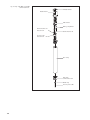
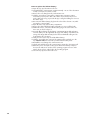
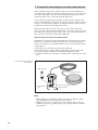
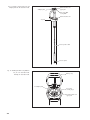
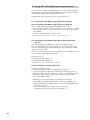
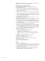
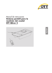
Fig. 2: Setup of the OTT ecoLog 800
communication unit.
Infrared interface
Radio antenna
SIM card slot
Battery compartment
Communication unit
desiccant unit
Communication unit
Pressure probe
desiccant unit
Pipe casing
Cap of the
communication unit
Rubber stop
Pressure probe cable
12
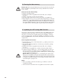
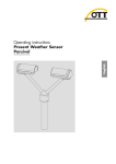
Connect the lithium battery plug to the socket of the electronic unit, as shown in
figure 3.
Fig. 3: Inserting the lithium battery.
Lithium battery, D type
Lithium battery, DD type
Plug
Socket
Velcro strip
Battery compartment
Electronic unit
Open the Velcro strip of the battery compartment.
Insert the lithium battery into the battery compartment (D type lithium battery:
insert the battery into the right-hand side (top) of the battery compartment; the
wiring of the D type lithium battery below the heat-shrinkable tubing must be
located at the side or bottom.)
Firmly close the Velcro strip around the lithium battery.
Slide the cap and the pipe casing of the communication unit back up to the
stop. Please note: Do not bend or pinch the battery lead.
Reinstall the screw fitting to the communication unit.
13
How to replace the lithium battery
Open the top cap/observation well cover.
Pull and hold the communication unit approximately 1 m out of the observation
well (a second person would be useful).
Remove the screw fitting from the communication unit.
Slide the cap and pipe casing of the communication unit approx. 50 cm
towards the pressure probe cable. (The rubber stop located on the pressure
probe cable (refer to Fig. 2) prevents the pipe casing from falling. Do not move
the rubber stop!)
Disconnect the lithium battery plug from the socket of the electronic unit, while
pressing the connector latch.
Open the Velcro strip of the battery compartment.
Remove the exhausted lithium battery and make sure not to pull the lead!
Within 10 minutes, connect the lithium battery plug to the socket of the electronic unit, as shown in figure 3.
Insert the lithium battery into the battery compartment (D type lithium battery:
insert the battery into the right-hand side (top) of the battery compartment; the
wiring of the D type lithium battery below the heat-shrinkable tubing must be
located at the side or bottom.)
Firmly close the Velcro strip around the lithium battery.
Slide the cap and the pipe casing of the communication unit back up to the
stop. Please note: Do not bend or pinch the lithium battery lead.
Reinstall the screw fitting to the communication unit.
Slowly and carefully reinsert the communication unit into the observation well.
Delete the power consumption value (power drawn from battery in ampere
hours) in the "Observer" window of the operating program. For more information, please refer to online help in the operating program.
Close the top cap/observation well cover.
14
5.2 Power supply using alkaline batteries
Note
At 0 °C, alkaline batteries have approx. 50 % of their original 20 °C capacity
and at –10 °C, they have approx. 35 % due to their design. If temperatures
drop below 0 °C at the measurement station it is recommended that lithium
batteries (OTT D or DD types) be used.
Caution
Only use the battery types specified (no rechargeable types).
Always use brand-new batteries. Do not mix used and new batteries.
Do not mix batteries from different manufacturers.
Properly dispose of exhausted batteries. Do not put them into domestic waste.
How to insert the alkaline batteries into the battery holder
Remove the screw fitting from the communication unit.
Slide the cap and pipe casing of the communication unit approx. 50 cm
towards the pressure probe cable.
Open the Velcro strip above the battery holder.
Remove the battery holder from the battery compartment.
Remove the cap of the battery holder by rotating it counter-clockwise.
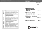
Insert 2 alkaline batteries (LR14 · AM-2 · MN 1400 · C) into the battery holder
as shown in figure 4. Ensure that the polarity is correct!
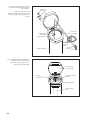
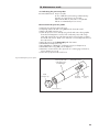
Fig. 4: Inserting alkaline batteries
into the battery holder.
Velcro strip
Electronic unit
Plug
Cap
Battery compartment
Socket
Battery holder
cable
Alkaline battery
(LR14 · AM-2 · MN 1400 · C)
Battery holder
Install the cap of the battery holder by rotating it clockwise.
Insert the battery holder into the battery compartment.
Firmly close the Velcro strip of the battery holder around the battery holder.
Slide the cap and the pipe casing of the communication unit back up to the
stop. Please note: Do not bend or pinch the battery holder lead.
Reinstall the screw fitting to the communication unit.
15
How to replace exhausted alkaline batteries
Open the top cap/observation well cover.
Pull and hold the communication unit approximately 1 m out of the observation
well (a second person would be useful).
Remove the screw fitting from the communication unit.
Slide the cap and pipe casing of the communication unit approx. 50 cm
towards the pressure probe cable. (The rubber stop located on the pressure
probe cable (refer to Fig. 2) prevents the pipe casing from falling.
Do not move the rubber stop!)
Open the Velcro strip above the battery holder.
Remove the battery holder from the battery compartment.
Remove the cap of the battery holder by rotating it counter-clockwise.
Remove the exhausted alkaline batteries and make sure not to pull the lead!
Within 10 minutes, insert 2 alkaline batteries (LR14 · AM-2 · MN 1400 · C)
into the battery holder as shown in figure 4 (ensure that the polarity is correct)
an install the cap of the battery holder by rotating it clockwise.
Insert the battery holder into the battery compartment.
Firmly close the Velcro strip of the battery holder around the battery holder.
Slide the cap and the pipe casing of the communication unit back up to the
stop. Please note: Do not bend or pinch the battery holder lead.
Reinstall the screw fitting to the communication unit.
Slowly and carefully reinsert the communication unit into the observation well.
Close the top cap/observation well cover.
Note
If you want to change from the currently used battery holder containing 2 alkaline
batteries (LR14 · AM-2 · MN 1400 · C) to lithium batteries prior to using the unit
follow the steps below:
Disconnect the battery holder cable from the socket of the electronic unit.
Carefully pull the plug straight upwards.
Open the Velcro strip above the battery holder.
Remove the battery holder from the battery compartment.
Insert the lithium battery as described in Chapter 5.1.
16
6 Inserting a SIM card
For communicating over the cellular network, a SIM card is required.
How to insert the SIM card:
Remove the screw fitting from the communication unit.
Slide the cap and pipe casing of the communication unit approx. 50 cm
towards the pressure probe cable, refer to Fig. 2.
Temporarily disconnect/remove batteries (refer to Sections 5.1 and 5.2).
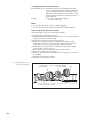
Insert the SIM card into the SIM card slot as shown in Fig. 5 (while making
sure not to touch the gold-colored contacts of the SIM card): press beveled
edge against the latch so that the latch slightly moves to the left allowing the
SIM card to engage. Make sure that the SIM card is fully inserted and
engaged!
Fig. 5: Inserting the SIM card.
Latch
SIM card slot
SIM card
Reconnect/insert batteries (refer to Sections 5.1 and 5.2).
Slide the cap and the pipe casing of the communication unit back up to the
stop. Please note: Do not bend or pinch the battery lead.
Reinstall the screw fitting to the communication unit.
Note
Changing/removing the SIM card:
Slide the latch into the direction indicated by the arrow.
The SIM card will then be ejected a few millimeters and can easily be pulled out.
17
7 If required: Connecting an external radio antenna
If the local signal strength of the cellular network prevents transmitting from the
closed observation well, an external radio antenna (accessory) is to be connected
to the OTT ecoLog 800. In this case, only the dedicated external radio antenna
specified by OTT must be used for this particular application.
You may fasten the external radio antenna to a suitable location using the shim
and nut supplied (drilling a hole for the thread of the external antenna is required:
Ø approx. 18 mm). For this installation, an individual solution to fasten the external antenna must be found depending on the station.
If the observation well is closed by a top cap you need to have a hole in the
observation well so that the antenna cable can be routed to the outside (to prevent
rain water from entering into the observation well, it is recommended to place the
hole on the side). If required seal the cable feedthrough.
How to connect an external radio antenna
Depending on the particular local situation (diameter of the observation well, type
of the top cap, and other mounting characteristics), the external radio antenna
must be connected prior to or during installation. Please note the relevant chapters
8.2 through 8.4.
Carefully unscrew the factory mounted antenna by hand.
Route the plug of the antenna cable through a hole in the observation well.
Connect the plug to the antenna socket and hand-tighten the locknut.
Fasten the external radio antenna to a suitable location outside the observation
well.
Fig. 6: Connecting an external
radio antenna.
Radio antenna
External radio antenna
Communication
unit
Plug of external radio antenna
Antenna socket
Note
When installing an external radio antenna, the minimum distance to other
electrical equipment or antennas must be at least 20 cm.
Additional accessories for optimizing the radio conditions at the station are
available on request (e.g. plastic top caps, top caps with external or internal
radio antenna).
18
8 Installing the OTT ecoLog 800 unit
The OTT ecoLog 800 is installed by hanging it into the observation well.
The necessary accessories and type of installation vary depending on the diameter
of the observation well and the design of the top cap:
2" observation wells
refer to 8.1
OTT top cap with cut-out for adapter plate
4" or 6" observation wells,
OTT top cap with cut-out for adapter plate
Observation wells of 3" in diameter and above,
Top caps without cut-out for adapter plate
Special case: observation wells beginning at 3" in diameter
without top cap, universal installation
refer to 8.2
refer to 8.3
refer to 8.4
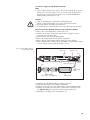
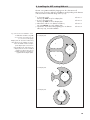
Fig. 7: Accessories for installation – Part 1
1 = drilled hole for OTT ecoLog 800
2 = cut-out for screws of the top cap
3 = cut-out for contact gauge
2
6" adapter plate
Adapter plates for observation wells having
other dimensions are available on request,
refer to the "Order numbers" chapter.
(Each adapter plate consists of two
parts and three bolts. In the figure, the
adapter plates are shown in installed
condition (on delivery, they are not
installed). Furthermore, an O-ring is
supplied with the adapter plates.
3
2
2
1
3
2
2
4" adapter plate
3
1
2
2
3
2
3" adapter plate
2
1
2
2
19
Fig. 8: Accessories for installation – Part 2
1 = drilled hole for OTT ecoLog 800
Universal suspension bracket
1
Note
Exposure to Radio Frequency Radiation: The antenna installation must provide
a separation distance of at least 20 cm from all persons and must not be
co-located, or operated in conjunction with any other antenna or transmitter.
The antenna gain, including cable loss must not exceed 2,85 dBi in Cellular
Band an 2,5 dBi in the PCS band.
8.1 Installing the unit into 2" observation wells,
top cap with cut-out
Required accessories: 2" OTT top cap with cut-out
How to install the OTT ecoLog 800
Preliminary work: If not already done, install batteries and SIM card,
refer to Chapter 5.
Open the top cap.
Determine the current depth using a contact gauge and note the measured
value.
Insert the pressure probe into the observation well.
Slowly and carefully lower the pressure probe by means of the pressure
probe cable!
Insert the communication unit into the observation well until the upper part of
the communication unit is fully seated on the top cap, refer to Fig. 9.
Set the operating parameters, refer to Chapter 9.
Close the top cap.
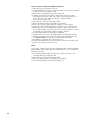
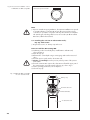
Fig. 9: Installing the OTT ecoLog 800
into a 2" observation well.
OTT top cap
Communication unit
Infrared interface
2" observation well
20
8.2 Installing the unit into 3", 4" or 6" observation wells,
top cap with cut-out for adapter plate
Required accessories: OTT top cap with appropriately sized cut-out and
compatible adapter plate (incl. O-Ring).
How to install the OTT ecoLog 800
Preliminary work: If not already done, install batteries and SIM card,
refer to Chapter 5.
Put the O-ring over the upper part of the communication unit and slide 20 mm
down.
Slide the lower part of the adapter plate (horseshoe-shaped) below the communication unit over the pressure probe cable and, on the communication unit,
slide it up horizontally until it touches the O-ring.
Slightly tilt the lower part of the adapter plate and, while rotating it, slide it up
over the O-ring.
Slide the O-ring and the lower part of the adapter plate up until the O-ring is
seated in one of the grooves provided for it.
Assemble the required upper part of the adapter plate (3", 4", or 6") as shown
in Figure 10 with the lower part using three M 2.5 socket head bolts.
Open the top cap.
3" observation wells: Determine the current depth using a contact gauge and
note the measured value.
Insert the pressure probe into the observation well.
Slowly and carefully lower the pressure probe into the observation well
with the pressure probe cable, refer to Fig. 11!
Insert the communication unit with adapter plate assembled into the observation well until the adapter plate and the upper part of the communication unit
are fully seated on the top cap. Align as shown in Figure 12.
4" and 6" observation wells: Use a contact gauge to determine the current depth
and record it (in the adapter plate, there is a cut-out for the contact gauge).
Set the operating parameters, refer to Chapter 9.
Close the top cap.
Fig. 10: Install the adapter plate to the
upper part of the communication unit.
Socket head bolt (x3)
Example: 4" observation well.
Adapter plate
upper part
(example: 4")
Adapter plate
lower part
Communication unit
upper part
O-Ring
Communication unit
Note
As an alternative to the procedure described above, you may install the
adapter plate independently of the communication unit. In this case, you have
to feed the pressure probe through the O-ring and the hole in the adapter plate
and to pull the entire pressure probe cable.
21
Fig. 11: Feed the communication unit and
adapter plate into the observation well.
Adapter plate
Communication unit
upper part
Cut-out for OTT
ecoLog 800
Communication unit
Top cap
Pressure probe cable
Pressure probe
Fig. 12: Installing the OTT ecoLog 800 into
a 3", 4" or 6" observation well.
OTT top cap
Example: 4" observation well.
4" adapter plate
Cut-out for
contact gauge
Communication unit
upper part
22
8.3 Installing the unit into observation wells of 3" in diameter
and above, top cap without cut-out for adapter plate
For this installation case, an individual solution to fasten the OTT ecoLog 800 must
be found depending on the station. Example: fix the universal suspension bracket
using an M6 hex head bolt/hex nut laterally to the upper end of the observation
well.
Required accessories: universal suspension bracket, mounting bolts, e.g.: M6
hex head bolt, washer, and M6 hex nut (all made of stainless steel).
How to install the OTT ecoLog 800
Preliminary work: If not already done, install batteries and SIM card,
refer to Chapter 5.
Open the top cap.
Drill 2 holes (Ø 6.5 mm, 20 mm apart) laterally into the upper end of the
observation well.
Please note: The universal suspension bracket is to be mounted in such a
way that there is a gap of a few millimeters between the top cap and the
infrared interface with the top cap closed. Otherwise there will be a risk of
damaging the infrared interface when the top cap is closed, refer to Fig. 14.
Attach the universal suspension bracket to the observation well using two M6
hex head bolts, washers, and M6 hex nuts. Use the two lower of the three
drilled holes of the universal suspension bracket, refer to Fig. 13.
Pass the pressure probe through the cut-out of the universal suspension bracket.
Slowly and carefully lower the pressure probe into the observation well
with the pressure probe cable.
Pass the communication unit through the holes of the universal suspension
bracket until the communication unit is seated on the universal suspension
bracket, refer to Fig. 14.
Determine the current depth using a contact gauge and note the measured
value.
Set the operating parameters, refer to Chapter 9.
Close the top cap.
Note
If protection against vandalism is required M6 threads are to be tapped into
the observation well instead of mounting the unit by means of hex nuts.
23
Fig. 13: Mounting diagram for universal
suspension brackets in observation wells
of 3" and above.
Example: 4" observation well
2x hex nut,
2x washer
Minimum clearance (A) of the upper hole
to the upper edge of the opened top cap:
43 mm!
2x drilled hole,
Ø 6.5 mm
20 mm clearance
Observation well
A
Cut-out for
OTT ecoLog 800
Universal
suspension
bracket
2x hex
head bolt
Fig. 14: Installing the OTT ecoLog 800 into
observation wells of 3" diameter and
above with a top cap without cut-out.
Example: 4" observation well.
Communication
unit upper part
Top cap
upper part
Universal suspension
bracket
Infrared interface
Communication
unit
24
8.4 Installing the unit into observation wells of 3" in diameter
and above, without top cap, universal installation
For this installation case, an individual solution to fasten the OTT ecoLog 800 must
be found depending on the station. Example: fix the universal suspension bracket
using an M6 hex head bolt/hex nut laterally to the upper end of the observation
well.
Required accessories: universal suspension bracket, mounting bolts, e.g.: M6
hex head bolts, washers, and M6 hex nuts (all made of stainless steel).
How to install the OTT ecoLog 800 (example)
Preliminary work: If not already done, install batteries and SIM card, refer to
Chapter 5.
Drill 2 holes (Ø 6.5 mm, 40 mm apart) laterally into the upper end of the
observation well, refer to Fig. 15.
Attach the universal suspension bracket to the observation well using two M6
hex head bolts, washers, and M6 hex nuts. Use the uppermost and lowermost
of the three drilled holes of the universal suspension bracket, refer to Fig. 15.
Pass the pressure probe through the cut-out of the universal suspension bracket.
Slowly and carefully lower the pressure probe into the observation well
with the pressure probe cable.
Pass the communication unit through the holes of the universal suspension
bracket until the communication unit is seated on the universal suspension
bracket, refer to Fig. 14.
Determine the current depth using a contact gauge and note the measured
value.
Set the operating parameters, refer to Chapter 9.
Fig. 15: Mounting diagram for universal
suspension brackets in observation wells
of 3" and above.
Universal suspension
bracket
Example: 4" observation well
If required, you may fix the universal suspension bracket reversed by 180° as well.
The socket head bolts will then be easily
accessible. In small diameter observation
wells, you may not be able to place the
optical reading head on the infrared interface when establishing a communication
link. In such a case, position the reading
head in a maximum distance of 25 cm
above the infrared interface.
Cut-out for
OTT ecoLog 800
2x drilled hole, Ø 6.5 mm
40 mm clearance
Hexagon
bolts
Hex nuts
Washers
Observation
well
Note
If protection against vandalism is required M6 threads are to be tapped into
the observation well instead of mounting the unit by means of hex nuts.
25
9 Setting OTT ecoLog 800 operating parameters
To set the OTT ecoLog 800 operating parameters, you will need the "OTT Water
Logger Operating Program" PC software (WBSPL0.exe). This software is found on
the "OTT Water Logger Software" CD-ROM (accessory).
Hardware and software requirements: refer to CD product insert.
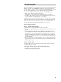
9.1 Installing the OTT Water Logger Operating Program
How to install the OTT Water Logger Operating Program
Insert the OTT Water Logger Software CD-ROM into the PC drive.
In the "\Software\Deutsch" 1) directory, start the "setup.exe" file (by e.g. double
clicking the file symbol) ➝ The Setup Assistant opens and guides you through
the installation.
Follow the installation instructions on the screen.
1)
Alternatively: change to the "\English", "\Français", or "\Español" directories.
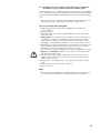
9.2 Establishing the PC/OTT ecoLog 800 communication link
(on site)
In the following chapters, establishing a communication link between the
OTT ecoLog 800 and a PC is described, which is a pre-requisite for the subsequent steps. The following description illustrates the various methods of establishing this communication link.
The communication between the OTT ecoLog 800 and a PC is established contactless via invisible infrared light (IrDA interface).
Required accessories:
OTT DuoLink reading head 1) or
OTT IrDA-Link USB reading head
1)
with PCB version "b": refer to the label on the connection line
How to establish a communication link
Start the operating program.
Change the language for the operating program as required:
press F3 function key (multiple times) until the required language appears.
In the start window, press the "Setup device" button ➝ The operating program
displays the "Basic operation" window. No operating parameters for the
OTT ecoLog 800 are visible yet.
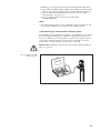
– Establishing a communication link to the OTT Duolink reading head:
Connect the OTT Duolink reading head to a serial PC port (COM1, etc.).
Place the OTT DuoLink reading head onto the OTT ecoLog 800 infrared interface, refer to Fig. 16.
In the operating program, select the communication path
"IrDA OTT DuoLink" and the serial port used (COM1, ...).
26
– Establishing up a communication link to the OTT IrDA-Link USB reading head:
Connect the OTT IrDA-Link USB reading head to a USB port on the PC. (USB
interface drivers must be installed, refer to separate installation instructions.)
Place the OTT IrDA-Link USB reading head onto the OTT ecoLog 800
infrared interface, refer to Fig. 16.
In the operating program, select the communication path
"IrDA OTT IrDA-Link".
Notes
The built-in infrared interface of a PC (standard for many notebooks) can only
be used with the Windows 95 and Windows NT operating systems!
9.3 Establishing the communication link from remote
If both installation and configuration of the OTT ecoLog 800 have been completed
the communication link may also be established using the cellular network, e.g.
for future modifications to the configuration. To perform these operations, the PC
on which the operating program is executed must be connected to a wired or
GSM modem. For more information, please refer to online help.
Please note: Establishing a communication link using the cellular network may
take up to a minute!
Fig. 16: PC/OTT ecoLog 800
communication link.
27
9.4 Setting OTT ecoLog 800 operating parameters
How to set the OTT ecoLog 800 operating parameters
Click the "Connect" button (alternatively: menu "OTT ecoLog 800",
"Connect" function) ➝ The operating program will read the current operating
parameters of the OTT ecoLog 800.
Setting operating parameters, refer to pages 29/30.
Optionally: "Set up cyclic data transmission via SMS" or "Set up cyclic data
transmission via GPRS", refer to pages 28/29.
Set date/time: Accept the proposed PC date/time or individually set the
date/time using the "Set date/time" function, also refer to Chapter 15.
Please note: The operating program automatically corrects any Daylight
Saving Time setting on the PC.
Click the "Save to device" button ➝ "Warning: Reset OTT ecoLog 800 and
delete data memory additionally?" Confirm by clicking "Yes" (recommended
for initial installation and reinstallations).
Please note: All measured values collected so far will be permanently lost!
Check the level of the measured value set (pressure sensor),
refer to Chapter 10.
Remove the OTT DuoLink/OTT IrDA-Link USB reading head.
Close the top cap/observation well cover.
Setting up the cyclic data transmission via SMS 1)
Enable the "SMS data transmission active" check box.
If necessary: Enable the "Authorize Roaming " and/or "Store GSM signal
strength" check boxes.
Click the "Settings" button ➝ The operating program starts a wizard for setting
all the necessary operating parameters.
Enter the receiver phone no. for the data SMS (phone number of a large
account or for a PC connected to a GSM modem).
Click the "Next" button.
If necessary: enter SIM PIN (4-digit) of the SIM card.
Click the "Next" button.
Set or enter the SMS-C phone no. of the network operator (phone number of
the SMS service center. By default, the SMS-C phone number is already saved
on the SIM card ➝ In this case, set to "SIM card".)
Click the "Next" button.
Select the mode of the SMS transmission.
Click the "Next" button.
Set the interval for transmitting the stored values.
Click the "Next" button.
Set the offset time for the transmission interval.
Click the "Exit" button.
Finally check the settings and correct as necessary.
Click the "OK" button.
1)
28
For further information, refer to online help.
Setting up the cyclic data transmission via GPRS 1)
Enable the "GPRS data transmission active" check box.
If necessary: Enable the "Authorize Roaming " and/or "Store GSM signal
strength" check boxes.
Click the "Settings" button ➝ The operating program opens a window displaying several tabs for setting all the necessary operating parameters.
Make the required settings in the "General", "Operator", "FTP" and "Time
sync." tabs. Please note: The SIM PIN for the SIM card used should be disabled! Otherwise enter the SIM PIN for advanced operation in the
"Modem/ITC" tab.
Click the "OK" button.
1)
For further information, refer to online help.
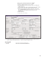
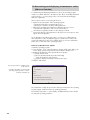
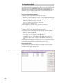
Fig. 17: Setting the OTT ecoLog 800 operating parameters using the OTT Water Logger Operating Program. The "Advanced operation …"
button is only visible, if the "Advanced operation …" check box is enabled in the "Options" window.
OTT ecoLog 800
Site number
Site name
station number, 10 characters (alphanumeric)
station name, max. 40 characters (alphanumeric)
29
Water level/pressure · temperature
Parameter number
sensor number, 4 characters (alphanumeric)
Parameter name
sensor name, max. 40 characters (alphanumeric)
Measurement type/Meas.range
Water level: depth or level · pressure
– Conductivity 0.001 … 2.000 mS/cm · 0.10 … 100.00 mS/cm
– Salinity: 2 … 42.00 PSU · 2 … 60.00 ppt
Unit +
– Pressure sensor: m, cm, feet, inch / bar, psi
– Temperature: °C · °F
– Conductivity: mS/cm · μS/cm
– Salinity: PSU · ppt
– TDS: mg/l
Decimal places
fixed specification, depending on the units and measuring range
– m: 3 or 2; cm: 1 or 0; feet: 2 or 1; inch: 1 or 0
– bar: 4 or 3; psi: 3 or 2
– °C: 2 or 1, °F: 2 or 1
– mS/cm: 3 or 2; μS/cm: 3
– PSU: 2; ppt: 2
– mg/l: 2
Depth to water – set newly
For the "Water level · depth" measurement type: Enter contact gauge value
Water level – set newly
For the "Water level · level" measurement type: Enter staff gauge value
(reference to level zero)
Pressure value – set newly
For the "Pressure" measurement type:
Enter reference pressure
Sample interval
5 s … 24 h: time delay at which the OTT ecoLog 800 records measured values
and stores them (store only, if sample interval = mean interval). The sample interval is set to a fixed time pattern (e.g. sample interval of 10 minutes, time pattern
…, 00:10, 00:20, 00:30, … .
Storage interval
5 s … 24 h: time period for which the OTT ecoLog 800 calculates an arithmetic
mean from the sample interval values and stores it. The storage interval must be
equal to or larger than the sample interval. The sample interval must be contained
in the storage interval as an integer number (e.g. sample interval: 10 minutes;
storage interval: 1 hour ➝ Every hour, the OTT ecoLog 800 stores an arithmetic
mean from 6 sample interval values).
Authorize Roaming
Allows the modem to book into other, external cellular networks (not only into the
cellular network specified by the SIM card). This might be of importance in regions
that are located close to a border, in which a foreign cellular network may have
better coverage but is more expensive.
SMS data transmission active
Refer to "Setting up the cyclic data transmission via SMS".
GPRS data transmission active
Refer to "Setting up the cyclic data transmission via GPRS".
Store GSM Signal strength
Stores the GSM signal strength in a separate channel. The sample interval in this
channel is 24 hours (factory setting: Storage delta = 1); irrespective of this, the
OTT ecoLog 800 saves 1 value per day in any case.
Additional settings for conductivity, salinity and TDS
Temperature compensation
(Conductivity)
Calculation method
(Salinity)
Store salinity
Store TDS
30
the mathematical algorithm on which the calculation of the specific conductivity at
a defined reference temperature is based. Possibilities: "Freshwater"; Saltwater";
Standard method 2510"; "ISO 7888/EN 27888"; "---" (none). For the "Standard
method 2510", the reference temperature can be selected: 20 °C or 25 °C.
the mathematical algorithm on which the calculation of the salinity is based. Possibilities: "Standard method"; "USGS 2311". With the calculation method USGS
2311, the unit is "ppt"; with the standard method the unit "PSU" is fixed.
With the check box activated, the datalogger saves the values. With the check box
deactivated, the instantaneous values are still visible in the observer window.
Other displays in the "Basic operation" window
Measuring range
System length
Date/time
Measuring range of the pressure probe, refer to Fig. 1.
Cable length including communication unit/pressure probe, refer to Fig. 1.
Internal date/time of the OTT ecoLog 800.
Battery lifetime (button)
The operating program calculates the approximate life of the different battery
types based on the settings made (at –20 and +20 °C ambient temperature in
each case).
Detailed information on the "Advanced operation" function can be found in the online help.
Factory settings
OTT ecoLog 800
Site number
Site name
OTT ecoLog 800 serial number
ecoLog 800 1
Parameter number
Measurement type
Unit
Decimal places
Sample interval
Storage interval
Water level/Pressure
0001
Water level · depth
m
2
1h
1h
Number
Name
Unit
Decimal places
Measuring range
Temperature compensation
Calculation method
Sample interval
Storage interval
Conductivity
0004
Specific Conductivity
mS/cm
2
0.10 …100.00 mS/cm
Fresh water
Standard method
1h
1h
Modem/ITC connected
Enabled
Disabled
Disabled
Disabled
Disabled
Authorize roaming
SMS data transmission active
GPRS data transfer active
Store GSM signal strength
Temperature
0002
°C
2
1h
1h
Salinity
0005
Salinity
PSU
TDS
0006
TDS
mg/l
2 … 42.00 PSU
1h
1h
1h
1h
In addition, the OTT ecoLog 800 records the supply voltage at a sample and storage interval of 1 hour (refer to online help).
31
9.5 Saving/loading an OTT ecoLog 800 configuration
The "Load from PC" and "Save to PC" functions are designed to archive the
OTT ecoLog 800 configuration on a PC. For example, you may configure multiple
OTT ecoLog 800 units using the same configuration. Additionally, the "Load from
PC" and "Save to PC" functions are required when using the "SMS command"
function (refer to online help).
How to save a configuration
From the "File" menu, select the "Save configuration" function (or use the button) ➝ The operating program saves the configuration under the name and
number of the OTT ecoLog 800. When changes are made to a configuration
that has already been saved, confirm by clicking "Yes" in the window "Warning. This configuration name already exists! Replace?" (otherwise, save the
configuration under another station number).
How to load a configuration
From the "File" menu, select the "Load configuration" function
(or use the button).
For an already opened configuration, confirm "Ignore changes?" message by
clicking "Yes" (if necessary, save configuration in advance).
In the "Stored OTT ecoLog 800 configurations" window, select the configuration by double-clicking it ➝ The operating program loads the configuration.
9.6 Importing/exporting an OTT ecoLog 800 configuration
To transfer an OTT ecoLog 800 configuration e.g. via USB flash drive or e-mail,
the Import/Export functions are available. Similarly, a configuration can be sent
via the Export function as an XML file to the OTT Hydras 3 user software. During
this process, the OTT Hydras 3 user software creates the entire station/sensor configurations in an OTT Hydras 3 operating range.
Available export/import formats
Export ("BIN" file)
Export to a text file
Export for the OTT Hydras 3 user software
Import ("BIN“ file)
The operating program stores all the necessary data of a configuration in a single
"*.BIN", "*.TXT" or "*.XML" file, depending on the export type.
How to export a configuration ("*.BIN" file)
This export type is required to transfer an OTT ecoLog 800 configuration as a
"*.BIN" file. Using the "Import configuration" function, the configuration can be
read back into the operating program.
From the "File" menu, select the "Export configuration" function.
In the "OTT ecoLog 800 – export configuration" window, edit the file name, if
necessary, select the storage location, and click "Store" ➝ The operating program saves the configuration in a "*.BIN" file.
Note
The file name of the "*.BIN" file is arbitrary. The operating program suggests a
combination of station number and station name.
32
How to export a configuration (text file)
This export type is required to transfer an OTT ecoLog 800 configuration for documentation purposes as a "*.TXT" file. This "*.TXT" file can be opened by means of
any text editor or word processing program.
From the "File" menu, select the "Export text file" function.
In the "OTT ecoLog 800 – configuration" window, edit the file name, if necessary, select the storage location, and click "Store" ➝ The operating program
saves the configuration in a "*.TXT" file.
Note
The file name of the "*.TXT" file is arbitrary. The operating program suggests a
combination of station number and station name.
How to export a configuration (OTT Hydras 3)
This export type is required to transfer an OTT ecoLog 800 configuration to the
OTT Hydras 3 user software. This "*.XML" file is read in via the Hydras 3 function
"File", "Import Station Configuration (XML)".
From the "File" menu, select the "Export Hydras 3 (XML)" function.
In the "OTT ecoLog 800 – XML configuration" window, check the file name,
select the storage location, and click "Store" ➝ The operating program saves
the configuration in a "*.XML" file.
Note
The file name of the "*.XML" file is arbitrary. To avoid affecting later data
transfer, it should not be changed. The operating program proposes a combination of station number and station name along with the ending "*.STATION.XML".
How to import a configuration
From the "File" menu, select the "Import configuration" function.
For an already opened configuration, confirm "Ignore changes?" message by
clicking "Yes" (if necessary, save configuration in advance).
In the "OTT ecoLog 800 configuration import" window, select the appropriate
"*.BIN" file and click "Open" ➝ The operating program reads in the configuration from the *.BIN" file. (Prior to this, save any configuration that is already
open).
Note
The factory default configuration is found on the "OTT Water Logger Software"
CD-ROM.
33
10 Determining and displaying instantaneous values
(Observer function)
For determining and displaying instantaneous values, the operating program
includes a so-called "Observer". The Observer also allows a manually determined
measured value, e. g. contact gauge value, to be entered into the datalogger
(Observer registration).
Various options can be set concerning the observer:
Options in the start window of the operating program:
– Directly and exclusively opening the Observer, or
– Opening of a window to set the operating parameters
Effect of an optionally entered Observer registration (pressure sensor):
– The Observer registration is only used as a check value or
– the Observer registration leads to a value change (set offset)
Suppress the display of the instantaneous value (pressure sensor) prior to entering an observer registration.
As an alternative to the following procedure, you may use a cellular phone to
show instantaneous values by SMS messages or to make observer entries. This
requires the "SMS info" feature to be enabled and set up. For more information,
please refer to online help in the operating program.
How to set the Observer options
Start the operating program.
From the "File " menu, select the "Options" function. (If the option dialog cannot be called, a password must first be entered. Refer to Chapter 12.)
Enable the checkbox(es) of the required Observer option(s):
– Only observer mode
– Do not calculate manual input value with scaling
(only check value/no value change);
– Suppress display of instantaneous value before input;
Click the "OK" button.
Fig. 18: Input window to establish options
for the observer.
For further information on protecting the
operating program by means of a password refer to Chapter 14.
The combination of "Only observer mode" and a password protects the operating
program against unauthorized input of operating parameters.
The "Advanced operation..." option displays an additional button in the window
for setting the operating parameters.
34
How to open the Observer function
Start the operating program.
Establish the PC/OTT ecoLog 800 communication link, refer to Chapters
9.2 or 9.3.
Depending on the option set: In the start window of the operating program,
either select "View Instantaneous values" or "Setup device" and in the subsequent window, select the "View Instantaneous values" function in the "OTT
ecoLog 800" menu ➝ The OTT ecoLog 800 starts an instantaneous value measurement and the "Observer" window opens:
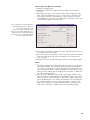
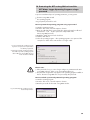
Fig. 19: Display/input window "OTT Water
Logger Operating Program – Observer".
The window displays the current
instantaneous value for all measurements.
Furthermore, the window displays the sensor
number/name, the current battery voltage,
the amount of power used from the batteries
up to now, and the date and time.
If necessary: Input Observer registration into the entry field of the pressure sensor and click on the "Store" button.
If necessary: Start new instantaneous value measurement: click on the "Refresh"
button (" Automatic refresh" starts an instantaneous value measurement
every 5 seconds).
Exiting the Observer: Click the "Exit" button and close the operating program.
Notes
The OTT ecoLog 800 stores each call of the Observer function in an info chan-
nel with date and time. After reading in and accepting into the OTT Hydras 3
user software, this information can be displayed in the evaluation window of a
sensor using the "Info Data" > "Station" > Displays" function ("Observer registration general"). Similarly, they are visible via the "View data" > "Table" function of the operating program.
If the " Do not calculate manual input value with scaling" check box in the
"Options" window is enabled, the OTT ecoLog 800 also saves the input check
value as well as the current instantaneous value. After reading in and accepting into the OTT Hydras 3 user software, this information can be displayed in
the evaluation window of a sensor using the "Info Data" > "Sensor" > "Displays" function ("Observer registration with check value). Similarly, they are
visible via the "View data" > "Table" function of the operating program.
35
11 Reading data
How to read data (on site)
Start the operating program.
Establish the PC/OTT ecoLog 800 communication link, refer to Chapters
9.2 or 9.3.
Press the "Download data" button in the start window ➝ The operating program displays the available sensors and the possible period for downloading
in the "Download data" window. If these values are not visible: Press the
"Connect" button.
Select the desired sensors or "All sensors".
Select the desired read period or "All". (The row above the entry field shows
the complete time period for which there are data.)
Click the "Connect" button ➝ The operating program copies the measured values from the OTT ecoLog 800 to the PC. The data is then available in the raw
data directory of the operating program.
If necessary: Change to the "View / Export data" function to display/export
measured values and/or to export to another software application.
Click the "Main menu" button.
Fig. 20: Downloading data.
Possible alternatives for downloads:
Using the operating program and a cellular network
In conjunction with a modem connected to the PC, a communication link may
be established via a cellular network (read data remotely), refer to online help.
Using the "OTT Hydras 3 (Basic)" application software
From the tree, select the desired station by double clicking it. In the following
window, make the necessary settings and click the "Start" button. For further
information, see the online help for the OTT Hydras 3 (Basic).
36
12 Exporting data
After downloading to the operating program, the measured value and information
data can be found in the "RAWDATA" sub-directory of the program directory
(default setting: "C:\Program files\OTT\OrpheusMini_CTD\RAWDATA"). To transfer to an external application, you may export the data in various formats:
CSV – Structured text file in CSV format (Comma-Separated Values);
Excel – Microsoft Excel spreadsheet program;
OTT Hydras 3 – Raw data format for the OTT Hydras 3 user software;
OTT MIS – OTT-specific file format for automatically importing into the measurement database of the OTT Hydras 3 user software.
Using the "Export options" dialog window, you may set the location for saving
and, for the CSV format, various export parameters. The data will remain available in the sub-directory after export. If required, you may explicitly delete it.
Info data can only be exported to the OTT Hydras 3 user software.
How to export the data
Step 1 – Make export settings:
Click the "View / Export data" button in the start window.
In the "View / Export data" window, click the "Export options" button, refer to
Fig. 21.
Set the path to the location of the required export format (default setting:
"C:\Program files\OTT\OrpheusMini_CTD\Export"). No path can be set for
the Excel format: The operating program automatically opens Microsoft Excel
during export and displays the data in a new workbook. For the "Hydras 3"
format, the "?" button can be used to automatically find the installation directory of OTT Hydras 3.
For the "CSV" format: set "Field separator", "Dec. separator", "Date format",
and "Time format". For the date and time formats, the typical Windows placeholders may be used.
Step 2 – Export data:
From the list, select the desired station/sensor (multiple selections possible).
Click the "Export ..." button.
Confirm the message about successful export by clicking "OK".
If required, delete the exported data: Click the "Delete" button.
(Station/sensor must still be selected.)
Confirm the message by clicking "Yes".
37
13 Displaying data
After downloading to the operating program, the measured value and information
data can be found in the "RAWDATA" sub-directory of the program directory
(default setting: "C:\Program files\OTT\OrpheusMini_CTD\RAWDATA"). For an
initial check, you may display the data graphically and numerically and print
them, if required.
How to display data graphically
Click the "View / Export data" button in the start window.
From the list, select the desired station/sensor (multiple selections possible - a
maximum of 6 will be displayed; info data can only be displayed numerically).
Click the "Graphic" button ➝ The operating program displays the window presenting the graphical view of the selected data;
– Show ruler: "F12" function key. Move ruler: Arrow keys ← →.
– Zoom in: Use the mouse to drag the desired area.
– Zoom out: "F12" function key.
Print graphic: From the "File" menu, select the "Print" function.
Close graphic: From the "File" menu, select the "Exit" function (or ).
How to display data numerically
Click the "View / Export data" button in the start window.
From the list, select the desired station/sensor (multiple selections possible, a
maximum of 6 will be displayed).
Click on the "Table" button ➝ the operating program displays the window with
the numerical view of the data in the OTT data protocol;
– Only display measured values: select "Values".
– Highlight special areas (only with information data): Select "Observer &
operation", "Alarm & limit", "Communication & faults", "Faults & service
log".
Printing the numerical display: From the "File" menu, select the "Print" function.
Closing the numerical display: Select the "Exit" button (or ).
How to delete data
From the list, select the desired station/sensor (multiple selections possible).
Click the "Delete" button.
Confirm the message by clicking "Yes".
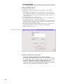
Fig. 21: Viewing/exporting data.
38
14 Protecting the OTT ecoLog 800 unit and the
OTT Water Logger Operating Program using a
password
To prevent unauthorized input of operating parameters, you may protect
the OTT ecoLog 800 unit and
the operating program:
using a separate password for each.
How to protect the operating program using a password
Start the operating program.
From the "File" menu, select the "Options" function.
Enter an eight-digit (max.) password into the "Password" input box. Allowed
characters 0 … 9, A … Z. (This password is independent of the
OTT ecoLog 800 password.)
Enable the "Only observer mode" check box.
Click the "OK" button.
Close the operating program ➝ The operating program is now protected: The
"Setup device" button in the start window is no longer visible.
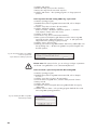
Fig. 22: Protecting the operating program
by means of a password – Input window
for defining a password.
A password protected operating program is
reasonable only if the operating program
starts in Observer mode ("Only observer
mode" check box enabled)!
Please note:
If the password is lost, you can no longer configure or parameterize the OTT
ecoLog 800 on this PC. If this occurs contact OTT HydroService.
The password assigned here only applies to the operating program installed on
this PC. The OTT ecoLog 800 unit is not protected by this password!
How to unlock a password-protected operating program
Start the operating program.
From the "File" menu, select the "Options" function.
Enter the password into the "OTT ecoLog 800" window.
Fig. 23: Unlocking the operating program –
Password input window.
39
Click the "OK" button.
Disable the "Only observer mode" check box.
Remove the entry from the "Password" input box.
Click the "OK" button ➝ The operating program is no longer password
protected.
How to protect the OTT ecoLog 800 using a password
Start the operating program.
Establish the PC/OTT ecoLog 800 communication link, refer to Chapters
9.2 or 9.3.
Click the "Setup device" button in the start window.
Click the "Advanced operation …" button.
(Button not visible? ➝ Enable the "Advanced operation ..." check box
in the "Options" function in the "File" menu.)
Click the "Connect" button.
From the tree view, select "Communication Interface".
Enter a password of maximum eight characters into the "OTT ecoLog 800
password" input box. Allowed characters 0 … 9, A … Z. (This password is
independent of the operating program password.)
Click the "Save to device" button.
Warning: "Reset OTT ecoLog 800 and delete data memory additionally?" Confirm by clicking "No" ➝ The OTT ecoLog 800 is now protected against unauthorized operation.
Fig. 24: Protecting the OTT ecoLog 800 by
means of a password –
Input window for defining a password.
Please note: If the password is lost, you can no longer configure or parameterize the OTT ecoLog 800. If this occurs contact OTT HydroService.
How to unlock a password-protected OTT ecoLog 800
Start the operating program.
Establish the PC/OTT ecoLog 800 communication link, refer to Chapters
9.2 or 9.3.
Click the "Setup device" button in the start window.
From the "OTT ecoLog 800" menu, select the "Enter password" function.
Enter password.
Click the "OK" button.
Confirm the "Password accepted! OTT ecoLog 800 unlocked" message by
clicking "OK".
Click the "Connect" button ➝ The operating program downloads the current
OTT ecoLog 800 operating parameters.
Fig. 25: Unlocking the OTT ecoLog 800 –
Password input window.
40
15 Setting date and time
The internal clock of the OTT ecoLog 800 is a high-accuracy realtime-clock. It runs
as soon as batteries are installed in the OTT ecoLog 800. After the batteries are
removed, the clock will continue to run for approximately 10 minutes. After a
longer period of power loss, the OTT ecoLog 800 will lose the date and time.
When batteries are reinstalled, the OTT ecoLog 800 adopts the date and time of
the last stored measured value, with one minute added to the stored time. The
date and time are set using the operating program.
How to set the date and time
Start the operating program.
Establish the PC/OTT ecoLog 800 communication link, refer to Chapters
9.2 or 9.3.
Click the "Setup device" button in the start window.
Select the "Date/time" function in the "OTT ecoLog 800" menu ➝ The operating program reads the date and time from the OTT ecoLog 800 and opens the
"OTT ecoLog 800 – date/time" window.
Fig. 26: Setting the OTT ecoLog 800
date and time.
If necessary: click the "Refresh" button ➝ The OTT ecoLog 800 reads the date
and time again.
If necessary: Adjust the desired values in the two input fields.
Click the "Set date/time" button ➝ The operating program sets the
OTT ecoLog 800 date and time to the PC time/date or to the values set.
Click the "Exit" button.
Please note: If the PC is in Daylight Saving Time (ID: PC (DST)), the operating
program automatically uses the standard time without DST correction. To obtain
continuous time series, it is a good idea not to use Daylight Saving Time in the
OTT ecoLog 800.
In connection with a GPRS remote data transfer and the "Time synchronization"
function, it is necessary to reference the time to UTC/GMT and to set the time
zone of the station in the "Advanced operation", "OTT ecoLog 800" window, refer
to online help.
Note
When the unit is put back into service, it may be appropriate to erase the data
memory after having set date and time, refer to Chapter 16.
41
16 Erasing the data memory
Please note: After erasing the data memory, the measured values stored in the
OTT ecoLog 800 are permanently lost! If necessary download measured values
before erasing!
How to erase the data memory
Start the operating program.
Establish the PC/OTT ecoLog 800 communication link, refer to Chapters
9.2 or 9.3.
Click the "Setup device" button in the start window.
Select the "Delete data memory" function in the "OTT ecoLog 800" menu.
Acknowledge the "Are you sure you want to delete data memory?" warning by
clicking "Yes"➝ The operating program erases the complete data memory of
the OTT ecoLog 800 (all measurement channels including the info channel). The
OTT ecoLog 800 then determines and stores the water level, the water temperature and the specific conductivity again using the sample interval settings set.
17 Updating the OTT ecoLog 800 firmware
If required, you have the option of updating the OTT ecoLog 800 firmware (operating system software). This makes sense, if e.g. devices delivered at different
times are to receive the same operating system version. Updating is carried out
via the operating program. According to availability, an updated version of the
OTT ecoLog 800 firmware can be found on the internet site "www.ott.com" in the
"myOTT" area.
How to update the firmware
Download the new version of the firmware (File: e.g. "spl21m_V1.10.1.bin")
from the internet site.
Move the file "spl21m_VX.XX.X.bin" to the directory, in which the operating
program is located.
Establish the PC/OTT ecoLog 800 communication link, refer to Chapters
9.2 or 9.3.
From the "OTT ecoLog 800" menu, select the "Firmware update" function.
Confirm message by clicking "Yes" ➝ The operating program copies the new
firmware to the OTT ecoLog 800. The OTT ecoLog 800 then determines and
stores the water level, the water temperature and the specific conductivity again
using the sample interval settings set.
Please note: During updating process, avoid breaking the communication
link (e.g. by accidentally removing the OTT DuoLink from the infrared interface
of the OTT ecoLog 800.) If the communication link is aborted, the firmware will
no longer be executable! Similarly, no other programs should be started or files
opened during the copying process!
Notes
If there are multiple ".bin" files in the directory you will have to select the
required file manually.
The measurements saved in the OTT ecoLog 800 are not lost after an update.
42
18 Maintenance work
18.1 Cleaning the pressure probe
Recommended interval: Every 12 months
In case of difficult local measuring conditions (heavy
deposits): as required every 4 to 6 months.
(Measurements that are inaccurate or not plausible
indicate a contaminated pressure sensor.)
How to clean the pressure probe
Open the top cap/observation well cover.
Completely remove the OTT ecoLog 800 from the observation well.
Remove the black protective cap.
Clean the pressure sensor carefully using a brush and water. Clean graphite
electrodes and temperature sensors for the conductivity sensor with soapy
water and cotton buds. Lime scale deposits can be removed using a common
household scale remover. Make sure to follow the use and safety instructions for
the scale remover!
Rinse the pressure probe thoroughly with clear water!
Reattach the black protective cap.
Recommendation: Calibrate the conductivity sensor (see Chapter 18.4).
Reinstall the OTT ecoLog 800, refer to Chapter 8.
Determine current reference value by means of a contact gauge and enter it,
refer to Chapters 9.4 or 10.
Close the top cap/observation well cover.
Fig. 27: Cleaning the pressure probe.
Pressure probe with
conductivity sensor
and datalogger
Black
protective cap
Temperature sensor
Graphite
electrodes
Conductivity
sensor
Pressure Sensor
43
18.2 Replacing the desiccant capsules
Recommended interval: Depending on the level of air humidity at the station,
every 12 to 24 months and when replacing the batteries.
There is a humidity indicator on the desiccant capsule.
When this indicator changes its color from blue to pink
the desiccant capsule has to be replaced, irrespective of
the time elapsed.
Quantity:
2 (1x pressure compensation capillary,
1x communication unit).
Notes
Store the desiccant capsule only in its original packaging.
Use only desiccant capsules that are fitted with a blue humidity indicator.
How to replace the desiccant capsules
A) Desiccant capsule for pressure compensation capillary
Open the top cap/observation well cover.
Pull and hold the communication unit approximately 1 m out of the observation
well (a second person would be useful).
Remove the screw fitting from the communication unit.
Slide the cap and pipe casing of the communication unit approx. 50 cm
towards the pressure probe cable. (The rubber stop located on the pressure
probe cable (refer to Fig. 2) prevents the pipe casing from falling.)
Pull the desiccant capsule container of the pressure compensation capillary
from the holder, as shown in Fig. 28.
Remove the cap of the container by rotating it counter-clockwise.
Remove the exhausted desiccant capsule.
Install new desiccant capsule. Labeling must face towards pressure compensation capillary.
Install the cap by rotating it clockwise.
Reinsert the container into the holder.
Fig. 28: Replacing the pressure
probe desiccant capsule.
Container for
desiccant capsule
Pressure compensation capillary
desiccant capsule
Pressure compensation capillary
44
Cap
B) Desiccant capsule for communication unit
Remove the exhausted desiccant capsule of the communication unit, as shown
in Figure 29.
Install new desiccant capsule.
Fig. 29: Replacing the communication
unit desiccant capsule.
Communication unit
desiccant capsule
Slide the pipe casing of the communication unit back up to the stop.
Please note: Do not bend or pinch the battery lead.
Reinstall the screw fitting to the communication unit.
Slowly and carefully reinsert the communication unit into the observation well.
Close the top cap/observation well cover.
18.3 Checking/replacing the batteries
Refer to Chapter 5
18.4 Calibrating the conductivity sensor
The goal of the calibration is to determine the so-called "cell constant" for the conductivity sensor. To do this, it is necessary to check the zero point and to carry out
a conductivity measurement with a standardized calibration solution.
The cell constant – as well as the unchanging geometric measurements, the materials used and the construction of the conductivity sensor – takes account of the
aging process of the electrodes.
Recommended interval: every 12 months (after every cleaning)
with difficult local measuring conditions (heavy deposits):
as required every 4 to 6 months
Required accessories:
standardized calibration solution, calibration container
(see Chapter 2, "Order numbers")
45
Caution: For an optimum calibration process, the OTT ecoLog 800 and the calibration solution must be at the surrounding temperature!
How to calibrate the conductivity sensor
Carefully clean the pressure probe and dry well (see Chapter 18.1).
Start the operating program.
Set up the PC/OTT ecoLog 800 communication link (see Chapter 9.2).
Press the "Setup device" button. (Button not visible? ➝ deactivate the "Only
observer mode" check box in the "Options" function in the "File" menu and
restart the operating program.)
Select the "Calibrate conductivity sensor" function in the "OTT ecoLog 800"
menu.
Press the "Start zero point test" button. The operating program starts an instantaneous value measurement and updates this every 5 to 6 seconds. If the measurement result displayed (blue triangle) is not in the green area ➝ clean the
conductivity sensor again and dry it well.
Press the "End zero point test" button.
Select the calibration solution used. Alternatively, select "Other ..." and enter
the appropriate conductivity value.
Add the calibration solution to the calibration container (filling height approx. 3/4).
Place the OTT ecoLog 800 into the calibration container (screw-on cover in
place) and tighten the screw-on cover by hand. Caution: There must not be
any air bubbles in the slot of the conductivity sensor! If necessary, lightly shake
the calibration container.
Press the "Start calibration" button. The operating program starts the instantaneous value measurement again and continuously updates it.
Wait until the values for conductivity and temperature do not change for several updates. The operating program displays the current and newly calculated
cell constant. Caution: Temperature values shown in red ➝ the conductivity
sensor is not at the temperature of the calibration solution! New cell constant
shown in red ➝ the cell constant lies outside the valid range.
Press the "End calibration" button.
Confirm the resulting question: "Save new cell constant?":
– cell constant is within the tolerance range ➝ "No"
(conductivity value is in the green area)
– Cell constant is outside the tolerance range and within the valid range ➝
"Yes" (conductivity value is in red area + current cell constant is shown in
black)
If the cell constant is outside the valid range ➝ error message.
Close the operating program.
Rinse the pressure probe thoroughly with clear water!
Reinstall OTT ecoLog 800 (see Chapter 8).
Determine current reference value with a contact gauge and enter it
(see Chapter 9.4 or 10).
Close the top cap/observation well cover.
Dispose of the used calibration solution!
Notes
Only use the calibration solution once!
Always store the calibration solution in a closed container! (The carbon dioxide
in the surrounding air and evaporation can change the conductivity value.)
Avoid water entering the calibration solution! Always dry the calibration con-
tainer carefully after calibration.
Calibration solution can be disposed of in the normal public sewer system!
The OTT ecoLog 800 saves the last three cell constants in a history (see
"Advanced operation ...", channel "Conductivity").
46
19 Error messages
When faulty measurements or a malfunction occur, the OTT ecoLog 800 stores
one of the following error messages in the data memory instead of a measured
value.
Err
Err
Err
Err
00
01
03
05
Err 06
Err 10
Internal error (automated measurement)
Internal error (A/D conversion error)
Measuring range exceeded
An input value required for the measurement calculation is not in the
valid range (example: the temperature value needed for the calculation
of the salinity (standard method) is outside of the valid range :
0 °C ≤ t ≤ 35.0 °C)
An input value for the measurement calculation is missing
Measured value (still) not recorded
Internal errors indicate a device fault, if they occur repeatedly.
20 Troubleshooting/remedy
No communication possible
(operating program/OTT ecoLog 800)
Password programmed?
➝ Enter correct password.
Batteries installed?
➝ Install batteries.
Alkaline batteries: Battery voltage lower than approx. 1.9 V
➝ Replace the batteries.
Lithium battery: Battery exhausted?
➝ Replace the battery.
Pressure probe cable damaged?
➝ Send OTT ecoLog 800 to factory for repair.
Infrared interface dirty?
➝ Clean the infrared interface carefully using a damp, soft cloth.
Setting measured value not possible?
➝ Scaling module missing. Check configuration*
(for advanced operation, refer to online help).
Communication starts and then aborts.
Alkaline batteries: Battery voltage lower than approx. 1.9 V
➝ Replace the batteries.
Lithium battery: Battery exhausted?
➝ Replace the battery.
Faulty measured values
Temperature values faulty
➝ Check configuration* (for advanced operation, refer to online help).
Pressure sensor values faulty
➝ Check configuration* (for advanced operation, refer to online help).
➝ Check the pressure compensation capillary in the communication unit
(blocked?). Clean as necessary.
➝ Check pressure sensor for contamination. Clean as necessary.
* The default factory configuration is located on the "OTT Water Logger Software" CD-ROM.
47
Conductivity values erroneous
➝ check configuration* (for advanced operation, see online help).
➝ check conductivity sensor for contamination. If necessary, clean and then
recalibrate
Calculated salinity values erroneous (Err 05)
➝ check configuration* (for advanced operation, see online help).
➝ input value is outside valid range:
– salinity by standard method
1.0 °C ≤ t ≤ 35.0 °C for salinity 2.0 PSU ≤ salinity ≤ 42.0 PSU
– Salinity by "USGS 2311" method
0 °C ≤ t ≤ 30.0 °C for salinity 2.0 ppt ≤ salinity ≤ 60.0 ppt
Observer does not display calculated salinity values
➝ values lie outside the valid range:
– salinity according to standard method
2.0 PSU ≤ salinity ≤ 42.0 PSU
– salinity according to "USGS 2311" method
2.0 ppt ≤ salinity ≤ 60.0 ppt
No measured values in database
Configuration incorrect?
➝ Check configuration* (for advanced operation, refer to online help).
Alkaline batteries: Battery voltage lower than approx. 1.9 V
➝ Replace the batteries.
Lithium battery: Battery exhausted?
➝ Replace the battery.
Communication through cellular network not possible/
not successful
No transmission parameters (operator, etc) configured
➝ Check the operating parameters entered, refer to Chapter 9.4.
Alkaline batteries: Battery voltage lower than approx. 1.9 V
➝ Replace the batteries.
Lithium battery: Battery exhausted?
➝ Replace the batteries.
SIM card missing
➝ Insert the SIM card, refer to Chapter 6.
Incorrect PIN
➝ Check PIN, refer to Chapter 9.4.
GSM signal too low
➝ Check whether an external radio antenna should be used, refer to
Chapter 7.
No measured values present (by transmitting data)
➝ Wait for the next data interval.
* The default factory configuration is located on the "OTT Water Logger Software" CD-ROM.
48
21 Repair
In case of a device malfunction, use Chapter 20, Troubleshooting/remedy to
see if you can resolve the problem yourself.
In case of device failure, please contact the OTT repair center (or alternatively
your local OTT sales representative):
OTT Hydromet GmbH
Repaircenter
Ludwigstraße 16
87437 Kempten · Germany
Phone +49 831 5617-433
Fax
+49 831 5617-439
[email protected]
Please note: Have a faulty OTT ecoLog 800 checked and repaired only by the OTT repair center. Never attempt to repair the unit yourself! Any repairs or
attempted repairs carried out by the customer will void any warranty.
22 Notes about the disposal of old units
Within the member countries of the European Union
In accordance with the European Union guideline 2002/96/EC, OTT takes back
old devices within the member countries of the European Union and disposes of
them in an appropriate way. The devices concerned by this are marked with the
symbol shown aside.
For further information on the return procedure, please contact your local sales
contact. You will find the addresses of all sales partners in the internet on
"www.ott.com". Please take into consideration also the national implementation
of the EU guideline 2002/96/EC of your country.
For all other countries
After putting the unit out of service, properly dispose of the OTT ecoLog 800.
Observe the regulations applicable in your country for the disposal of
electronic devices.
Never dispose of the OTT ecoLog 800 in the normal domestic waste.
Materials used
Refer to Chapter 23, Technical data.
49
23 Technical data
Water level
Measuring range
Resolution*
Accuracy (linearity + hysteresis)
Long-term stability (linearity + hysteresis)
Zero
Overload-resistant without permanent mechanical
damage (Pressure sensor)
0 ... 0.4 bar
0 ... 1 bar
0 ... 2 bar
0 ... 4 bar
0 ... 10 bar
Units
Pressure sensor
Temperature-compensated operating range
Temperature
Measuring range
Resolution
Accuracy
Units
4 bar
10 bar
15 bar
25 bar
40 bar
m, ft, inch, bar, psi, pascal
ceramic; temperature-compensated
–5 °C … +45 °C (ice free)
–25 °C ... +70 °C
0.01 °C
±0.1 °C
°C · °F
Power supply
2 x 1.5 V alkaline battery (C cell); or
Lithium battery, D type, 3.6 V / 13 Ah; or
Lithium battery, DD type, 3.6 V / 26 Ah
Conductivity
Measuring ranges
Resolution
0.001 … 2.000
0.10 … 100.00
Accuracy
0.001 … 2.000
0.10 … 100.00
Units
0.001 … 2.000
0.10 … 100.00
0 … 4 m water column (0 ... 0.4 bar)
0 … 10 m water column (0 ... 1 bar)
0 … 20 m water column (0 ... 2 bar)
0 … 40 m water column (0 ... 4 bar)
0 …100 m water column (0 ... 10 bar)
0.001 m; 0.1 cm; 0.01 ft; 0.1 inch
0.0001 bar; 0.001 psi
± 0.05 % full scale
± 0.1 %/a full scale
± 0.1 % full scale
0.001 … 2.000 mS/cm
0.10 … 100.00 mS/cm
mS/cm
mS/cm
0.001 mS/cm
0.01 mS/cm
mS/cm
mS/cm
±0.5 % of measured value (at least ±0.001 mS/cm)
±1.5 % of measured value (at least ±0.01 mS/cm)
mS/cm
mS/cm
mS/cm · μS/cm
mS/cm
Current consumption
Sleep mode
Read (IrDA)
Measuring operation
GSM receiving
GSM transmitting
Lifetime (1 hour sample interval, one transfer per day)
Lithium battery (26 Ah)
Lithium battery (13 Ah)
Alkaline batteries
110 μA
76 mA
65 mA
13 mA
160 mA
> 10 years minimum
> 5 years minimum
> 1 year minimum (high quality battery types).
* For value ranges ±32.750 m; ±3275.0 cm; ±327.50 ft; ±3275.0 inch; ±3.2750 bar; ±32.750 psi
50
Clock
Design
Accuracy
Buffer period for battery replacement
Interface
Modem
SIM card
Antenna
Temperature range, operating
Temperature range, storage
Air humidity
Data memory
Measurement memory
Number of measured values
Number of logical channels
Physical channels (input signals)
Sample interval
Storage interval (mean interval)
Individually configurable functions
Real-time clock
±8 seconds/month (at +25 °C)
7 minutes max.
Infrared (IrDA)
Type: Telit G30; GSM; GPRS
quadband (850/900/1800/1900 MHz)
1.8 / 3 V
Built-in, robust and weather-proof, external antenna optionally
available
-30 °C … +85 °C
-40 °C … +85 °C
5 % … 95 % (non-condensing)
4 MB
Approx. 500,000
6 + 1 info channel
Water level/pressure
Temperature
Conductivity
Supply voltage
GSM signal strength
Minimum supply voltage during GSM transmission
5 seconds … 24 hours
5 seconds … 24 hours
– Basic or advanced operation
– 5 extended sample intervals with start/stop time indication,
support for pumping tests
– Selection of units
– Number of decimal places
– Pressure/level measurement or depth measurement
– With consideration of the local gravitational acceleration
– Compensate for water density using salinity and temperature
– Temperature compensation for conductivity. Options: Freshwater;
Saltwater; Standard method 2510 (reference temperature: 25 °C
or 20 °C); ISO 7888 / EN 27888; none
– Salinity (standard method or USGS 2311)
– Display of instantaneous values with level monitoring function
– Password protection
– Measured value processing: Calculation of mean; delta storage;
scaling function; extreme value storage; limit control of the sample
interval
– Virtual sensor/virtual terminal
– Alarm management
– Remote data transfer
Cellular networks
Supported frequencies
Direct SMS data transmission
Data retrieval through direct connection
GPRS functionality
GSM 850 / 900 / 1800 / 1900 MHz (quadband)
Supported
Supported
Supported
51
Mechanical Data
Can be installed in observation wells
– Top caps with cut-out (OTT, HT)
– With adapter plates for top caps
With cut-out (OTT, HT)
– With universal suspension brackets for top caps
Without cut-out/universal installation
Dimensions
Communication unit (L x Ø)
Pressure probe (L x Ø)
System length (cable length including
communication unit/pressure probe)
Weight
Communication unit (incl. lithium batteries, DD type)
Pressure probe
Pressure probe cable
Material
Pressure probe housing
Seals
Separating membrane
Cable jacket
Communication unit housing
Conductivity sensor:
Type of protection
Communication unit
Pressure probe
Desiccant
Performance classification of the sensors
according to DIN EN ISO 4373
Measurement reliability
Temperature range
Relative air humidity
2"
3", 4", 6"
> 2"
520 mm x 50 mm
317 mm x 22 mm
2 … 200 m ±1 % ±5 cm
Approx. 0.920 kg
Approx. 0.430 kg
Approx. 0.082 kg/m
POM, stainless steel 1.4539 (904 L)
Viton
Al2O3 ceramics (96 %)
PUR
Aluminum, PA-GF
ABS, graphite (electrodes) and stainless steel 1.4539 (904L)
IP 67 (submersion depth 1 m, submersion duration 30 min)
IP 68
2 capsules (2.65 g silica gel), recommended replacement interval:
Once per year
Performance class 1
Temperature class 2
Class 1
EMC limits
According to EC 204/108/EC
ETSI EN 301 486-1/-7
EN 61326-1
EN 60950-1:2006 + A11:2009 + A1:2010
FCC ID
RI7T56KT1
52
Appendix A – OTT ecoLog 800 declaration of conformity
53
OTT Hydromet GmbH
Document number
55.447.001.B.E 03-0613
Ludwigstraße 16
87437 Kempten · Germany
Phone +49 831 5617-0
Fax
+49 831 5617-209
[email protected] · www.ott.com