1
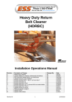
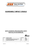
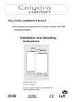
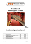
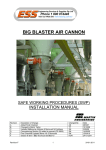
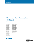
HEAVY DUTY RETURN BELT CLEANER (HDRBC) SAFE WORKING PROCEDURES (SWP) INSTALLATION MANUAL Revision A B C D E Revision E Description of Change Added Final Checklist Updated Melbourne Address & Removed SA Address Final Checklist Updated Items 4 & 5 Reversed Updated manual as per CR2634 Revised drawing F0147 - Rev G & F0141 Rev F 1 Changed By AS SH SH SH KO Date 28/5/07 3/08/09 15/04/10 12/08/10 14/03/11 14/03/2011 ENGINEERING SERVICES and SUPPLIES OFFICE DETAILS ESS HEAD OFFICE 11-13 TRADERS WAY PO BOX 121 CURRUMBIN QLD 4223 P: (07) 5589 2000 F: (07) 5598 1353 ESS MACKAY 1 PROGRESS STREET PO BOX 5755 MACKAY MC QLD 4740 P: (07) 4952 4600 F: (07) 4952 4717 ESS PERTH 19 CLAVERING ROAD BAYSWATER WA 6053 P: (08) 9370 3155 F: (08) 9272 5130 ESS MAITLAND UNIT 2 BARTON COURT 6 JOHNSON STREET MAITLAND NSW 2320 P: (02) 4932 3544 F: (02) 4932 3611 ESS WOLLONGONG 1/20 DOYLE AVENUE PO BOX 343 UNANDERRA NSW 2526 P: (02) 4272 4422 F: (02) 4272 4434 ESS MELBOURNE 4/314 Governor Road BRAESIDE VIC 3195 P: (03) 9580 0388 F: (03) 9587 5199 ESS EMERALD 11/115 ROBERTS STREET EMERALD QLD 4720 P: (07) 4982 4855 F: (07) 4987 5118 ESS GLADSTONE 2/34 CHAPPLE STREET PO BOX 1475 GLADSTONE QLD 4680 P: (07) 4972 3759 F: (07) 4972 2866 ESS ADELAIDE P: (08) 8262 8955 F:(08) 8262 4944 ESS KALGOORLIE 4/235 HAY STREET PO BOX 10471 KALGOORLIE WA 6430 P: (08) 9021 7991 F: (08) 9021 7291 ESS MOUNT ISA 6 TRADERS WAY PO BOX 1554 MT ISA QLD 4825 P: (07) 4749 4580 F: (07) 4749 3019 CUSTOMER SERVICE NUMBER 1800 074446 TOLL FREE FROM ANYWHERE IN AUSTRALIA Revision E 2 14/03/2011 WARRANTY NOTE ESS WARRANTS the ESS Product to be free of defects both in materials and workmanship for a period of 12 months from the date of despatch of the product from the ESS factory. The warranty given by ESS in this regard will extend only to replacing or repairing product shown to be defective. The warranty also is subject to the following restrictions: (a) Installation of the product contrary to the instructions contained in the supplied manual will void such warranty absolutely; (b) The warranty will not extend to any liability for injuries incurred and which result from the use of the product contrary to the instructions in the manual; (c) Save as prescribed by law, ESS will not be liable for any damage sustained by a purchaser or a third party by way of consequential loss arising out of defects in the product. You are asked to note that ESS offers purchasers a service whereby either: (a) It will install the product and certify the correctness of such installation, or (b) Certify the correctness or otherwise of the installation of the product by third parties. This certification service is designed to ensure that you obtain the full benefit of the ESS warranty hereby provided. If you would like to take advantage of the installation certification service provided, please contact ESS regarding the service. THE CONTENTS OF THIS MANUAL ARE COPYRIGHT TO: ESS ENGINEERING SERVICES AND SUPPLIES PTY LTD ALL RIGHTS RESERVED Information contained herein is for use in the operation of the HEAVY DUTY RETURN BELT CLEANER, purchased from ESS and cannot be passed on to any other party without express permission, in writing, from ESS. ESS Despatch Department to complete. Client should retain for warranty. Purchaser / Client: Purchase Order / Contract No.: Site: Conveyor No/s.: Despatch Date: No. Supplied: Description / Part Numbers: Comments: Revision E 3 14/03/2011 INDEX SECTION 1 SAFETY SECTION 2 INTRODUCTION SECTION 3 PREPARATION FOR INSTALLATION SECTION 4 INSTALLATION SECTION 5 COMMISSIONING SECTION 6 OPERATOR TRAINING SECTION 7 ROUTINE MAINTENANCE AND SERVICE SECTION 8 INSTALLATION ARRANGEMENT DRAWING SECTION 9 EXPLODED PARTS DRAWING Revision E 4 14/03/2011 SECTION 1 - SAFETY The HEAVY DUTY RETURN BELT CLEANER is designed to be quickly and easily serviced by appropriate personnel. Under no circumstances should servicing or installation of the cleaner be carried out whilst the belt is in operation. The conveyor must be shut down and locked out before any person enters or reaches into the conveyor enclosure. Ensure that only suitably qualified and trained personnel install and service this product. Ensure that all site and statutory safety procedures are followed. SECTION 2 - INTRODUCTION The ESS HEAVY DUTY RETURN BELT CLEANER (HDRBC) is a return belt cleaner designed to remove fugitive material from the inner side of the return strand of a conveyor belt. The HDRBC is normally located before the tail pulley, gravity take up, mid-drive unit or any other position where fugitive material can become trapped between the belt and pulley, causing damage or wear to the belt, pulley or pulley lagging. The ESS HDRBC features a urethane blade for long-life and efficient cleaning, and can also be supplied in Mines Department approved FRAS urethane for underground coal and similar applications. The main feature, however, of the ESS HDRBC, is the unique urethane torsion strap suspension. This suspension arrangement allows pre-tensioning of the HDRBC onto the belt by simply rotating the support pipes. The HDRBC is held lightly against the belt surface, and “floats” with the belt movement, eliminating the “chatter” commonly associated with gravity-type Vee Ploughs. NOTE: The ESS HDRBC is directional, and is not suitable for reversing belts. Figure 1: Typical installation positions and use of HD-RBC. Revision E 5 14/03/2011 SECTION 3 - PREPARATION FOR INSTALLATION 1. ASCERTAIN INSTALLATION POSITION As previously noted, the ESS HDRBC is intended to be installed on the inside return conveyor belt, just before the tail pulley, gravity take-up or similar. The position selected for installation should have a flat, taut belt (see notes in Section 4), and good access for installation and maintenance. Suitable support structure for attachment of the HDRBC mounts is also required. 2. OBSERVE BELT CONDITIONS Does the belt reverse or roll back on stopping? If so, do not use this HDRBC. An ESS Diagonal Plough is used on reversing belts. Is the belt flat and taut or does it sag or cup Does the belt bounce or vibrate? The HDRBC will operate best on a flat, vibration free belt. Achieve these conditions by appropriate use of flat rollers – SEE NOTES IN SECTION 4. If a flat, stable belt cannot be achieved contact ESS before proceeding with the installation. 3. TRIAL ASSEMBLE HDRBC Familiarise yourself with the parts and operation of the HDRBC. Plan the installation. Measure and pre-manufacture any mounting brackets that may be required. Note! Dimensions shown here are for the HDRBC Figure 2 : Typical Installation dimensions – HD-RBC. Revision E 6 14/03/2011 4. ASSEMBLE THE NECESSARY TOOLS AND SAFETY EQUIPMENT REQUIRED FOR THE JOB. SECTION 4 - INSTALLATION 4.1 NOTES: BEFORE PROCEEDING WITH INSTALLATION, ENSURE THAT THE CONVEYOR BELT DRIVE IS FULLY ISOLATED AND LOCKED OUT. DO NOT ALTER SPECIFIED HDRBC INSTALLATION DIMENSIONS TO AVOID SITE OBSTACLES – THE HDRBC WARRANTY WILL BE VOIDED IF NOT INSTALLED TO SPECIFIED DIMENSIONS. 4.2 DIMENSIONAL NOTES AND CHECKLIST The following tolerances may be applied to installation dimensions quoted in this section: 4.3 The dimension from top of belt to centre of support pipes is 324 ± 5 mm. The dimension between support pipes centres is DIM C ± 5 mm. Tolerance on support pipe squareness to conveyor centreline (viewed in plan) is maximum 5 mm out of square for each 1000 mm of pipe length. Tolerance on support pipe parallelism is maximum 5 mm out of parallel for each 1000 mm of pipe length. The centre line of plough should align with the centre line of the conveyor. The maximum deviation is 5 mm either side of centre, measured at the nose and at the tail of the HDRBC frame. NOTES ON BELT SUPPORT The HDRBC must be installed on a flat belt to achieve best results, and to avoid damage to the unit caused by misalignment of supports. The following procedure may be used to achieve a flat belt: ESS recommends that a return roller should be installed within 150 mm of the front edge of the cleaner nose (before or after). A second roller after the HDRBC will only be required if the following factors are present: Low belt tension Visible or measurable belt deflection under the weight of the HDRBC Belt edge cupping or curling Belt vibrations that are transferred into the HDRBC Where a belt is in a high tension condition, and the unit is installed close to a tail or bend pulley, a second support roller is unlikely to be required unless excessive vibration is detected. When installing support rollers under a belt in the area of a HDRBC, care must be taken not to alter the line of the conveyor belt. This may result in the distance from the top of belt to the support pipes being altered. If the line of the belt is altered, the HDRBC installation dimensions should be re-checked and adjusted if necessary. Revision E 7 14/03/2011 4.4 Installation Procedure Step 1 Place the HDRBC without support pipes or tensioning straps on the belt at the selected position. Ensure that the HDRBC frame rear cross member is 90° to the centre line of the belt (see fig3). Step2. Measure 124mm forward from the nose of the HDRBC, and 324mm perpendicular upwards from the belt surface (see fig 1). Mark this point on the stringer or conveyor structure on each side of the belt, ensuring that the line between the points is at 90° (square) to the belt. These points represent the centre lines of the front support pipe and front mount sets. Step 3 Install the front support pipe and mounts at the above point. Installation may involve cutting holes or attaching brackets to conveyor structure (see typical mount arrangements in previous section, and cut out details below). Seek site Engineer’s approval before modifying conveyor structure. Figure 3 Table 1 Belt Width 900 1050 1200 1350 1500 1600 1800 2000 2200 2400 2500 Pipe Centres (Dim C) 277 352 502 577 727 927 1077 Step 4 427 627 827 1027 Measure back from the above point a distance equal to dimension “C” from above table, and parallel to the belt (i.e. 324mm from belt surface). This point represents the centre line of the rear support pipe and mounts. Figure 4 Revision E 8 14/03/2011 Step 5 Install rear support pipe and mounts, as previously described. STOP: At this point, check that the two support pipes are exactly 324mm from centre of pipe to top of belt. Check that the two pipes are exactly Dim C apart from centre to centre. Check that the two pipes are square to the belt and parallel to each other. Step 6 If not already done, withdraw the pipes though one mount and slide on the urethane tensioning straps – one on the front pipe and two on the rear. Centralise the HDRBC and pipe supports to the belt and/or stringers, and align the straps to the holes in the HDRBC frame. The holes should easily align without force. Insert bolts and bolt the strap ends to the HDRBC frame. If the strap holes do not align with the frame holes, DO NOT bend or distort the strap to align them. Re-check pipe installation dimensions to correct the misalignment. Distorting the straps may result in vibration and failure of the HDRBC and the straps. If after re-checking, the hole in the straps do not match the holes in the frame immediately contact ESS. Step 7 Attach one end of the safety chain by shackle to the HDRBC frame. Loop the other end around the front support pipe and connect to itself with the other shackle, allowing approximately 70-80mm of slack for blade wear. Tighten the lockscrews securing the tensioning straps to the support pipes. Step 8 At one end of each support pipe drill a hole large enough for insertion of an appropriate tensioning bar (say 25 hole). Refer to drawing F0141 in this manual. As an alternative, a pipe wrench may be used for tensioning. Step 9 If support pipes are over long, trim off the appropriate amount, remembering to leave enough pipe exposed for tensioning (see Step.8 above). Step 10 From outside the conveyor enclosure; rotate the front support pipe to just place a slight downward load on the front tensioning strap, but without inducing any visible deflection in the strap. Tighten the lockscrew(s) on the support pipe mounts to retain the adjustment, and to prevent movement of the pipe. Repeat for the rear pipe and straps. Installation of the HDRBC is now complete. The conveyor can be returned to service and commissioning of the HDRBC can commence. Revision E 9 14/03/2011 Figure 5 Revision E 10 14/03/2011 SECTION 5 - COMMISSIONING Step 1 Start the belt - Observe the action of the HDRBC. The HDRBC should ride smoothly on the belt with no chatter or vibration. If vibration is present, repeat the tensioning procedure in Step10 of Section 4, but slightly increase the contact pressure. Do not over-tension the HDRBC - it will not increase cleaner efficiency but will increase blade wear. If vibration is present after moderate tensioning, contact ESS on 1800 074446 within Australia, or +61 7 5598 1077 from outside Australia, for further advice. Step 3. Demonstrate the system to the operating supervisors and crew Call the supervisors responsible for maintenance and operation to the site. Make a short run of the system. Show the operator how to adjust and operate the system. Step 4. Secure the system for production Follow plant procedure to secure the conveyor for actual production. SECTION 6 - OPERATOR TRAINING The decision to purchase ESS Belt Cleaning equipment is the first step toward achieving a clean plant. The next step is the correct installation of the equipment as outlined in this manual. The final step is to maintain and service the equipment to guarantee ongoing performance. ESS strongly recommends that operators are correctly trained to maintain ESS equipment, or that ESS is commissioned to maintain the equipment on a scheduled basis. The benefits of efficient cleaners outweigh the cost of maintaining the cleaners many times. 1. Adhere to all local safety rules. 2. Give a “Hands On” instruction with the conveyor system shut down. 3. Give a “Hands On” instruction with the conveyor system running. 4. All service must be recorded and given to a person of responsibility. 5. Encourage the person being trained to look for possible problems developing on the system, eg. excessive or unusual vibrations, belt tracking excessively, tears or damage to belt, seized idlers, missing bolts, etc. A warning to the maintenance department to rectify small problems can save the company a lot of money in repairs and production costs. 6. Impress how important it is to maintain and service the cleaners correctly. Revision E 11 14/03/2011 SECTION 7 - ROUTINE MAINTENANCE AND SERVICE Although the HDRBC requires only minimal maintenance, regular inspection and servicing is the key to effective conveyor belt cleaning. It is recommended that the cleaner be inspected once per week. Actual service intervals will vary considerably from plant to plant. CAUTION! DO NOT REACH INTO THE CONVEYOR UNDER CIRCUMSTANCES WHILST THE CONVEYOR IS RUNNING. ANY ROUTINE EXTERNAL INSPECTION Step 1. Visually inspect the condition of the HDRBC. Observe the condition and action of the cleaner with the belt running. If vibration or other unusual conditions exist, shutdown the conveyor and carry out a Shutdown Service as described below. Step 2. Observe the condition of the blade. If necessary (and if plant rules allow it), hose any material build-up from the blade. DO NOT REACH INTO THE CONVEYOR WHILST IT IS RUNNING. If the blade is excessively worn or blade to belt contact is not even, shutdown the conveyor and carry out a Shutdown Service as described below. SHUTDOWN INSPECTION / SERVICE Step 1. Shut down and lock out the conveyor. Step 2. Visually inspect the blade. Check the condition of the urethane torsion straps, looking for cracks, cuts or any damage. Check that all fasteners are secure. If the blade is not excessively worn, and straps and fasteners are in good condition, check the tension of the cleaner and if necessary, re-tension as described in Section 4, Step 10. Service completed. If the blade or torsion straps are excessively worn or damaged, proceed. Step 3. Release the lockscrews on the HDRBC mounts to release tensioning pressure on the HDRBC. . Step 4. Remove the bolts securing the tensioning straps to the HDRBC mainframe. Remove the HDRBC frame and blade assembly from the conveyor enclosure and place in accessible area. Alternatively, if it is easier to access the HDRBC in-situ, place appropriate packing under the RBC frame to allow removal and replacement of the HDRBC blade. Step 5. Clean and inspect the HDRBC blade, and replace if necessary. Inspect closely the tensioning straps and replace if damaged. See section 4 for description of HDRBC assembly. Step 6. Re-install all parts, ensuring that all fasteners are adequately secured. Re-tension the HDRBC as described in Section 4. Step 7. Remove locks and return the conveyor to service. Revision E 12 14/03/2011 SECTION 8 – INSTALLATION ARRANGEMENT DRAWING Revision E 13 14/03/2011 SECTION 9 – EXPLODED PARTS DRAWING Revision E 14 14/03/2011 FINAL CHECKLIST Site:____________________________ Number: ____________________ Date: ____________________ Site Equipment No./Location: _________________________ Site Contact: __________________________ Completed By: _____________________________________ (Circle Yes or No Below) 1. Was equipment to ESS Specification? ______________________________ Yes/No Drawing No. Ref: _______________________________________ Attached? Yes/No If No, WHY ________________________________________________________________________________ _________________________________________________________________________________________ Will this affect performance? Yes/No If Yes, WHY _______________________________________________________________________________ _________________________________________________________________________________________ 2. Was this a standard service inspection installation? Yes/No If No, WHY ________________________________________________________________________________ _________________________________________________________________________________________ 3. Was work carried out as per procedure and JSA? Yes/No If No, WHY ________________________________________________________________________________ _________________________________________________________________________________________ 4. Is equipment fit for commissioning? Yes/No If No, WHY ________________________________________________________________________________ _________________________________________________________________________________________ 5. Was a final inspection carried out while plant was running? Yes/No If No, WHY ________________________________________________________________________________ _________________________________________________________________________________________ 6. Has anything changed from previous service / inspection / installation? Yes/No If Yes, WHAT ______________________________________________________________________________ _________________________________________________________________________________________ 7. Is equipment performance to Client expectations? Yes/No If No, WHY ________________________________________________________________________________ _________________________________________________________________________________________ ESS Signature: _____________________________ Revision E 15 Client Signature: _____________________________ 14/03/2011