1
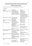
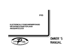
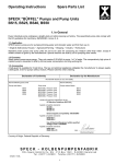
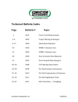
GUARDABELT IMPACT CRADLE SAFE WORKING PROCEDURES (SWP) INSTALLATION MANUAL Revision A B C D Revision D Description of Change Added Final Checklist Updated Melbourne Address & Removed SA Address Final Checklist Updated Items 4 & 5 Reversed Updated Drawing F0055 & F0007 1 Changed By AS SH SH KO Date 28/5/07 3/08/09 15/04/10 14/03/11 14/03/2011 ENGINEERING SERVICES and SUPPLIES OFFICE DETAILS ESS HEAD OFFICE 11-13 TRADERS WAY PO BOX 121 CURRUMBIN QLD 4223 P: (07) 5589 2000 F: (07) 5598 1353 ESS MACKAY 1 PROGRESS STREET PO BOX 5755 MACKAY MC QLD 4740 P: (07) 4952 4600 F: (07) 4952 4717 ESS PERTH 19 CLAVERING ROAD BAYSWATER WA 6053 P: (08) 9370 3155 F: (08) 9272 5130 ESS MAITLAND UNIT 2 BARTON COURT 6 JOHNSON STREET MAITLAND NSW 2320 P: (02) 4932 3544 F: (02) 4932 3611 ESS WOLLONGONG 1/20 DOYLE AVENUE PO BOX 343 UNANDERRA NSW 2526 P: (02) 4272 4422 F: (02) 4272 4434 ESS MELBOURNE 4/314 Governor Road BRAESIDE VIC 3195 P: (03) 9580 0388 F: (03) 9587 5199 ESS EMERALD 11/115 ROBERTS STREET EMERALD QLD 4720 P: (07) 4982 4855 F: (07) 4987 5118 ESS GLADSTONE 2/34 CHAPPLE STREET PO BOX 1475 GLADSTONE QLD 4680 P: (07) 4972 3759 F: (07) 4972 2866 ESS ADELAIDE P: (08) 8262 8955 F:(08) 8262 4944 ESS KALGOORLIE 4/235 HAY STREET PO BOX 10471 KALGOORLIE WA 6430 P: (08) 9021 7991 F: (08) 9021 7291 ESS MOUNT ISA 6 TRADERS WAY PO BOX 1554 MT ISA QLD 4825 P: (07) 4749 4580 F: (07) 4749 3019 CUSTOMER SERVICE NUMBER 1800 074446 TOLL FREE FROM ANYWHERE IN AUSTRALIA Revision D 2 14/03/2011 WARRANTY NOTE ESS WARRANTS the ESS Product to be free of defects both in materials and workmanship for a period of 12 months from the date of despatch of the product from the ESS factory. The warranty given by ESS in this regard will extend only to replacing or repairing product shown to be defective. The warranty also is subject to the following restrictions: (a) Installation of the product contrary to the instructions contained in the supplied manual will void such warranty absolutely; (b) The warranty will not extend to any liability for injuries incurred and which result from the use of the product contrary to the instructions in the manual; (c) Save as prescribed by law, ESS will not be liable for any damage sustained by a purchaser or a third party by way of consequential loss arising out of defects in the product. You are asked to note that ESS offers purchasers a service whereby either: (a) It will install the product and certify the correctness of such installation, or (b) Certify the correctness or otherwise of the installation of the product by third parties. This certification service is designed to ensure that you obtain the full benefit of the ESS warranty hereby provided. If you would like to take advantage of the installation certification service provided, please contact ESS regarding the service. THE CONTENTS OF THIS MANUAL ARE COPYRIGHT TO: ESS ENGINEERING SERVICES AND SUPPLIES PTY LTD ALL RIGHTS RESERVED Information contained herein is for use in the operation of the Guardabelt Impact Cradle, purchased from ESS and cannot be passed on to any other party without express permission, in writing, from ESS. ESS Despatch Department to complete. Client should retain for warranty. Purchaser / Client: Purchase Order / Contract No.: Site: Conveyor No/s.: Despatch Date: No. Supplied: Description / Part Numbers: Comments: Revision D 3 14/03/2011 INDEX SECTION 1 SAFETY SECTION 2 INTRODUCTION SECTION 3 INSTALLATION SECTION 4 COMMISSIONING SECTION 5 OPERATOR TRAINING SECTION 6 ROUTINE MAINTENANCE AND SERVICE SECTION 7 INSTALLATION ARRANGEMENT DRAWING SECTION 8 EXPLODED PARTS DRAWING Revision D 4 14/03/2011 SECTION 1 - SAFETY The Guardabelt Impact Cradle is designed to be quickly and easily serviced by appropriate personnel. Under no circumstances should servicing or installation of the cleaner be carried out whilst the belt is in operation. The conveyor must be shut down and locked out before any person enters or reaches into the conveyor enclosure. Ensure that only suitably qualified and trained personel install and service this product. Ensure that all site and statutory safety procedures are followed. SECTION 2 - INTRODUCTION The ESS Guardabelt Impact Cradle consists of an adjustable steel frame, fitted with impact absorbing rubber bars that are designed to be easily removed without the necessity of pulling out the cradle frame from the conveyor. The bars have a low friction UHMW-Polyethylene top wear surface. The cradle is fabricated to conform exactly to the troughed belt profile. The ESS Guardabelt Impact Cradle is designed to replace conventional impact idlers in the load zone of a conveyor. Under heavy impact loading the Guardabelt bars will easily outlast standard impact idlers, absorb shock loads and increase belt life by reducing material piercing. In addition to these benefits the Guardabelt impact bars are able to hold the belt flat under the skirting thereby virtually eliminating material spillage. To achieve these results however, the ESS Guardabelt Impact Cradle must be installed in the correct manner. Clearances and adjustments which are specified later are essential Revision D 5 14/03/2011 to the performance of the cradle. The cradles have been designed and manufactured to simply bolt into place on the conveyor stringers and achieve these clearances from a set of dimensions supplied by the client. The clearances should however be checked at installation to ensure that no fabrication error or design errors have resulted in incorrect installation position of the cradle. SECTION 3 - INSTALLATION Handling and Storage Instructions The ESS Guardabelt Impact Cradle is a sturdy and robust assembly. It is unlikely to be damaged during normal transport and handling procedures. Each Impact Cradle assembly is despatched individually and is suitable for forklift handling. Average weight, depending on belt width, is of the order of 300-500kg per assembly. The units are suitable for outdoor storage on site. Installation Procedure 1. Determine approximate installation position for each impact cradle on the conveyor and place the appropriate cradles adjacent to the installation area by use of a forklift, crane etc. 2. Before commencing installation or any work around the conveyor belt ensure that the belt is isolated and tagged. 3. The ESS Impact Cradle is intended to be installed between impact idler troughing assemblies. Multiple impact cradles will have an impact idler trough assembly between each successive cradle. Ensure that impact idler assemblies are either already installed or available at the installation site. If the idlers are already installed check that sufficient clearance is available between successive sets of rollers to fit an impact cradle. Standard impact cradles are 1200mm long and require 25mm clearance at each end between cradle bar and roller. Non standard cradles of 1400mm and 1500mm are also available. 4. NOTE: Revision D Assemble the necessary tools and safety equipment required for the job. BEFORE PROCEEDING WITH INSTALLATION, ENSURE THAT THE CONVEYOR BELT DRIVE IS FULLY ISOLATED AND LOCKED OUT. 6 14/03/2011 Fig 1. Guardabelt Impact Cradle Layout 5. Determine the installation position for the impact cradle/s. The impact cradle/s should be installed to cover the entire direct load area of the conveyor belt. For a short load zone this may mean one cradle and for longer load zones multiple cradles may be used. Having determined the position of the first impact cradle, disassemble one cradle for installation. This involves removal of the wing locks (two per side) and sliding off the wing bars from both sides. After this is done the four wing support assemblies can be slid from either side of the cradle. The centre bars can then be slid from the cradle base. Insert the cradle base onto the conveyor stringers in the appropriate position and align with stringers. Ensure that the base is centred and squared to the stringers and clamp into position. NOTE: If the conveyor belt is not already in place, the cradle can be lifted complete into position and installed without disassembly. This would require crane or fork handling. 6. Slide the centre bars onto the base frame and centre them on the base. 7. If not already in position, install an impact idler set either side of the impact cradle base ensuring that 25mm clearance will be available at both ends of the centre impact bars(Fig 1). Revision D 7 14/03/2011 8. Using a string line or straight edge ensure that the top of the centre bars is approximately 20mm below the top of the centre rollers of the impact idler frame (Fig 2). If this dimension is not approximately 20mm, packing of either the impact cradle base or the impact idler frames may be necessary to achieve this 20mm clearance. Once this clearance is achieved drill bolt holes in the stringers at appropriate position and bolt the cradle base in place. Alternatively, weld in place. NOTE: Accelerated bar wear will result from insufficient clearance. Belt damage may result from an excessive clearance - due to lack of belt support. Fig 2. Cradle Positioning 9. Re-assemble the cradle in reverse order of disassembly. The wing bars, that is the troughing bars, should also be approximately 20mm away from the troughing idler line (Fig 3). Fig 3. Cradle Setup Clearances Revision D 8 14/03/2011 Final adjustment. 10. Using the multiple hole adjustment, adjust the wing support arms so that the outer bar is brought up to be in line with the troughing idler rollers (Fig 4). Care should be taken to ensure that the outer bar is as close as possible to the roller line. If the bar is too high, accelerated wear will result. If the bar is too low, the belt may sag, resulting in material spillage. Fig 4. Wing Adjustment 11. Repeat the above procedure for all subsequent cradles. NOTE: IF YOU HAVE ANY PROBLEMS, OR ARE UNCLEAR ON ANY INSTALLATION STEP, CONTACT ESS ON OUR CUSTOMER SERVICE NUMBER 1800 074446. 12. Remove danger tags and return conveyor to service, following plant procedures. Revision D 9 14/03/2011 SECTION 4 - COMMISSIONING No special commissioning procedures are required for Guardabelt impact cradles. Provided the cradles are installed as per the drawing and instructions, then operational attention should not be required. A note on safety: No additional safety hazards are present with Guardabelt Impact Cradles other than normal conveyor belt dangers. In particular: Beware of moving conveyor belts. Beware of pinch points Do not attempt to install, maintain or disassemble any part of a conveyor belt without first isolating and tagging the conveyor drive. SECTION 5 - OPERATOR TRAINING Servicing Recommended dismantle & Hose down and reassemble every 6 months There are no operator serviceable or adjustable functions on an ESS Guardabelt Impact Cradle. No in-service procedures need to be followed, other than normal conveyor belt operating procedures. Safety As mentioned in Section 4, no additional safety hazards exist with an ESS Guardabelt Impact Cradle, other than normal conveyor belt dangers. Do not attempt to perform any job on or around a moving conveyor belt isolate and tag the belt first. Problems The operator, during routine conveyor inspections, should be alert to the following problem indicators: Smoke or burning rubber smell - the belt should be stopped immediately, and the problem located. It is far more likely to be a siezed impact idler or a skirting problem, but could possibly indicate an impact cradle fault. Leakage of material from skirts at load zone - this should be notified to the appropriate maintenance personnel for attention at the earliest plant stoppage. It may mean that skirting requires attention, and/or that the impact cradle wings require adjustment. Revision D 10 14/03/2011 SECTION 6 - ROUTINE MAINTENANCE AND SERVICE Safety Before attempting any maintenance on or around a conveyor belt, ensure that the belt drive is isolated and tagged. General The ESS Guardabelt Impact Cradle requires virtually no maintenance to operate under extreme conditions for thousands of hours. However, to achieve the best bar life and avoid the need for unscheduled bar change-outs, the following maintenance practices should be adopted. Routine Maintenance The cradles should be disassembled (Cradle Disassembly Procedure - page 13) and inspected for bar wear after one month of operation, and again after three months. Subsequent inspection frequency can be determined after the wear rate is assessed at these initial inspections. The UHMW-Polyethylene top cover of the bar is 8mm thick. The bars should be scheduled for change out when the top cover thickness reaches 2mm. TIP: During inspection, higher wear areas may be identified on some bars, or sections of bars. This is caused by uneven belt loading in the transfer point. Longer overall bar life may be achieved by noting the position of the bars at disassembly, and rotating the bars to a differeant position on re-assembly, much like rotating the tyres on a car. Non-Routine Maintenance (Trouble-Shooting) If the routine maintenance and scheduled bar change-outs are performed as per Routine Maintenance, non routine maintenance should be virtually non existent. However the following situations are possible. SYMPTOM POSSIBLE CAUSE REMEDY Smoke or burning rubber 1. Siezed idler. - Replace idler smell. 2. Overadjusted or damaged - Replace or adjust skirting skirting. rubber. 3. Worn out impact bar. - Disassemble impact cradle and replace bars. If bar life is short or wear is uneven, contact ESS. Material spillage under skirts. 1. Skirting rubber not - Adjust or replace skirting. adjusted or failed. 2. Impact cradle wings not - Adjust the cradle wings. adjusted up to belt. Revision D 11 14/03/2011 Cradle Disassembly Procedure The disassembly of an ESS Guardabelt Impact Cradle is a simple process. 1. Remove the slide locks from the outer wing bars (two per side). 2. Remove the securing bolt and nuts holding the wing assembly to the base (two per side). 3. Slide the entire wing assembly out from the belt about 50mm. 4. Slide the individual wing bars from the wing assemblies. Note the bar positions by numbering (with a marking pen or chalk). 5. Slide the wing frame assemblies from the base (four per side). 6. Repeat for the other side. 7. Slide the centre bars of the base (again noting the positions). 8. Inspect the bars for wear or damage. If severe or unusual wear is noted, contact ESS on 1800 074446 for advice. Cradle Re-assembly Re-assemble the cradle in reverse order of disassembly, paying attention to the following: If new bars are being fitted, or if existing bar wear is negligible, refit the bars in any order. If wear spots are evident on certain bars, rotate or rearrange bars on reassembly to maximise total bar life. Revision D 12 14/03/2011 SECTION 7 – INSTALLATION ARRANGEMENT DRAWING Revision D 13 14/03/2011 SECTION 8 – EXPLODED PARTS DRAWING Revision D 14 14/03/2011 FINAL CHECKLIST Site:____________________________ Number: ____________________ Date: ____________________ Site Equipment No./Location: _________________________ Site Contact: __________________________ Completed By: _____________________________________ (Circle Yes or No Below) 1. Was equipment to ESS Specification? ______________________________ Yes/No Drawing No. Ref: _______________________________________ Attached? Yes/No If No, WHY ________________________________________________________________________________ _________________________________________________________________________________________ Will this affect performance? Yes/No If Yes, WHY _______________________________________________________________________________ _________________________________________________________________________________________ 2. Was this a standard service inspection installation? Yes/No If No, WHY ________________________________________________________________________________ _________________________________________________________________________________________ 3. Was work carried out as per procedure and JSA? Yes/No If No, WHY ________________________________________________________________________________ _________________________________________________________________________________________ 4. Is equipment fit for commissioning? Yes/No If No, WHY ________________________________________________________________________________ _________________________________________________________________________________________ 5. Was a final inspection carried out while plant was running? Yes/No If No, WHY ________________________________________________________________________________ _________________________________________________________________________________________ 6. Has anything changed from previous service / inspection / installation? Yes/No If Yes, WHAT ______________________________________________________________________________ _________________________________________________________________________________________ 7. Is equipment performance to Client expectations? Yes/No If No, WHY ________________________________________________________________________________ _________________________________________________________________________________________ ESS Signature: _____________________________ Revision D 15 Client Signature: _____________________________ 14/03/2011