1
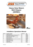
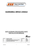
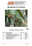
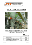
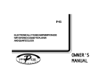
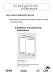
Guardaseal Belt Support System Installation Operations Manual Revision A B C D E F G H Revision H Description of Change Added Final Checklist Updated Melbourne Address & Removed SA Address Final Checklist Updated Items 4 & 5 Reversed Removed Mt isa contact details Updated format of manual Updated drawing F0251 Inserted updated drawing F0251 Updated office details 1 Changed By AS SH SH KO KO KO KO KO Date 28/5/07 3/08/09 15/04/10 21/6/12 11/9/12 5/1/13 11/2/14 11/3/14 11/03/2014 ENGINEERING SERVICES and SUPPLIES OFFICE DETAILS Location CURRUMBIN Address 11 – 13 Traders Way PO Box 121 Currumbin QLD 4223 [email protected] Unit 11 / 115 Roberts Street PO Box 1861 Emerald QLD 4720 [email protected] Unit 2/34 Chapple Street PO Box 1475 Gladstone QLD 4680 [email protected] Unit A 255 Dugan St Kalgoorlie WA 6430 PO Box 10471 Kalgoorlie WA 6433 [email protected] EMERALD GLADSTONE KALGOORLIE MACKAY MAITLAND PERTH TOWNSVILLE SOUTH AUSTRALIA WOLLONGONG Phone: (07) 4982 4855 Fax: (07) 4987 5118 Phone: (07) 4972 3759 Fax: (07) 4972 2866 Phone: (08) 9021 7991 Fax: (08) 9021 7291 Phone: (08) 9144 0689 Fax: (08) 9144 0682 KARRATHA VICTORIA Phone & Fax Phone: (07) 5589 2000 Fax: (07) 5521 0347 1 Progress Street Paget, QLD 4740 PO Box 5755 Mackay Mail Centre QLD 4741 [email protected] Unit 2 Barton Court 6 Johnson Street Maitland NSW 2320 [email protected] 19 Clavering Road Bayswater WA 6053 26 Midas Road Malaga WA 6090 [email protected] Unit 6 40-42 Carmel St Garbutt QLD 4814 [email protected] 5 Cormorant Court. Middleton. SA . 5213 [email protected] Unit 4 / 314 Governor Road Braeside VIC 3195 [email protected] Unit 1 / 20 Doyle Avenue PO Box 343 Unanderra NSW 2526 [email protected] Phone: (07) 4952 4600 Fax: (07) 4952 4717 Phone: (02) 4932 3544 Fax: (02) 4932 3611 Phone: (08) 9370 3155 Fax: (08) 9272 5130 Phone: (07) 4755 2776 Fax: (07) 4779 6236 Mobile: 0408 948 175 Phone: (03) 9580 0388 Fax: (03) 9587 5199 Phone: (02) 4272 4422 Fax: (02) 4272 4434 TOLL FREE 1800 074 446 FROM ANYWHERE IN AUSTRALIA VSS TOLL FREE 1800 300 877 Revision H 2 11/03/2014 WARRANTY NOTE ESS WARRANTS the Guardaseal Belt Support System to be free of defects both in materials and workmanship for a period of 12 months from the date of despatch of the product from the ESS factory. The warranty given by ESS in this regard will extend only to replacing or repairing product shown to be defective. The warranty also is subject to the following restrictions: (a) Installation of the product contrary to the instructions contained in the supplied manual will void such warranty absolutely; (b) The warranty will not extend to any liability for injuries incurred and which result from the use of the product contrary to the instructions in the manual; (c) Save as prescribed by law, ESS will not be liable for any damage sustained by a purchaser or a third party by way of consequential loss arising out of defects in the product. You are asked to note that ESS offers purchasers a service whereby either: (a) It will install the product and certify the correctness of such installation, or (b) Certify the correctness or otherwise of the installation of the product by third parties. This certification service is designed to ensure that you obtain the full benefit of the ESS warranty hereby provided. If you would like to take advantage of the installation certification service provided, please contact ESS regarding the service. Refer to the Final Checklist at the back of this manual. Visit the ESS website www.esseng.com.au to register your product warranty. THE CONTENTS OF THIS MANUAL ARE COPYRIGHT TO: ESS ENGINEERING SERVICES AND SUPPLIES PTY LTD ALL RIGHTS RESERVED Information contained herein is for use in the operation of Guardaseal Belt Support System, purchased from ESS and cannot be passed on to any other party without express permission, in writing, from ESS. Revision H 3 11/03/2014 INDEX SECTION 1 SAFETY SECTION 2 INTRODUCTION SECTION 3 INSTALLATION SECTION 4 COMMISSIONING SECTION 5 OPERATOR TRAINING SECTION 6 ROUTINE MAINTENANCE AND SERVICE SECTION 7 TROUBLE SHOOTING SECTION 8 INSTALLATION ARRANGEMENT DRAWING SECTION 9 EXPLODED PARTS DRAWING SECTION 10 FINAL CHECKLIST Revision H 4 11/03/2014 SECTION 1 - SAFETY The GUARDASEAL is designed to be quickly and easily serviced by appropriate personnel. Under no circumstances should servicing or installation of the cleaner be carried out whilst the belt is in operation. The conveyor must be shut down and locked out before any person enters or reaches into the conveyor enclosure. Ensure that only suitably qualified and trained personel install and service this product. Ensure that all site and statutory safety procedures are followed. Revision H 5 11/03/2014 SECTION 2 - INTRODUCTION The ESS Guardaseal Belt Support System consists of a telescoping steel frame, fitted with low friction UHMW-Polyethylene bars that are designed to be easily removed without the necessity of pulling out the support frame from the conveyor. The System is fabricated to conform exactly to the troughed belt profile (FIG. 1). FIG. 1 The ESS Guardaseal Belt Support System holds conveyor belts in a stable, sag free position to allow effective sealing. By minimising belt vibration and sag the Guardaseal Belt Support System reduces escaping material and risk of damage to the belt and conveyor accessories. Guardaseal bars provide a low friction, self lubricating surface for conveyor belts to skim over without heat builldup or undue wear on the belt surface or bars. The ESS Guardaseal Belt Support System is not intended to absorb impact. Revision H 6 11/03/2014 SECTION 3 - INSTALLATION Installation Procedure 1. Determine approximate installation position for each Support System on the conveyor and place the appropriate Systems adjacent to the installation area. 2. Before commencing installation or any work around the conveyor belt ensure that the belt is isolated and tagged. 3. The ESS Guardaseal Belt Support System is intended to be installed between idler troughing assemblies. Multiple Support Systems will have an idler trough assembly between each successive System. Ensure that the idler assemblies are either already installed or available at the installation site. If the idlers are already installed, check that sufficient clearance is available between successive sets of rollers to fit a Support System. Standard Systems are 1200mm long and require 25mm clearance at each end between System bar and roller (FIG. 2). If required, the Guardaseal Bars can be easily cut to suit on site. 4. Assemble the necessary tools and safety equipment required for the job. NOTE: BEFORE PROCEEDING WITH INSTALLATION, ENSURE THAT THE CONVEYOR BELT DRIVE IS FULLY ISOLATED AND LOCKED OUT. FIG. 2 Revision H 7 11/03/2014 5. Determine the installation position for the Support System/s The System/s should be installed to cover the entire skirted section of the conveyor belt. Having determined the position of the first Support System, place the first support frame onto the conveyor stringers in the appropriate position and align with stringers. Ensure that the support frame is centred and squared to the stringers and clamp into position. Repeat with other support frame. 6. Slide the telescoping supports onto the Guardaseal Bar at a distance apart the same as the support frames. Slide this assembly onto the support frames until the Guardaseal Bars are under the skirting. Adjust the telescoping frames so that the Guaraseal Bar sandwiches the belt firmly between the skirting and the Bar (FIG. 3). 7. If not already in position, install an idler set either side of the Support System ensuring that 25mm clearance will be available at both ends of the Guardaseal Bars (FIG. 2). 8. Repeat the above procedure for all subsequent Systems. NOTE: IF YOU HAVE ANY PROBLEMS, OR ARE UNCLEAR ON ANY INSTALLATION STEP, CONTACT ESS ON OUR CUSTOMER SERVICE NUMBER 1800 074446. 9. Remove danger tags and return conveyor to service, following plant procedures. FIG. 3 Revision H 8 11/03/2014 SECTION 4 - COMMISSIONING No special commissioning procedures are required for Guardaseal Support Systems. Provided the Systems are installed as per the drawing and instructions, then operational attention should not be required. A note on safety: No additional safety hazards are present with Guardaseal Support Systems other than normal conveyor belt dangers. In particular: Beware of moving conveyor belts. Beware of pinch points Do not attempt to install, maintain or disassemble any part of a conveyor belt without first isolating and tagging the conveyor drive. Revision H 9 11/03/2014 SECTION 5 - OPERATOR TRAINING Servicing There are no operator serviceable or adjustable functions on an ESS Guardaseal Support System. No in-service procedures need to be followed, other than normal conveyor belt operating procedures. Safety As mentioned in Section 4, no additional safety hazards exist with an ESS Guardaseal Support System, other than normal conveyor belt dangers. Do not attempt to perform any job on or around a moving conveyor belt isolate and tag the belt first. Problems The operator, during routine conveyor inspections, should be alert to the following problem indicators: Smoke or burning rubber smell - the belt should be stopped immediately, and the problem located. It is far more likely to be a seized impact idler or a skirting problem, but could possibly indicate an Support System fault. Leakage of material from skirts at load zone - this should be notified to the appropriate maintenance personnel for attention at the earliest plant stoppage. It may mean that skirting requires attention, and/or that the Support System wings require adjustment or are worn. Revision H 10 11/03/2014 SECTION 6 - ROUTINE MAINTENANCE AND SERVICE Safety Before attempting any maintenance on or around a conveyor belt, ensure that the belt drive is isolated and tagged. General The ESS Guardaseal Support System requires virtually no maintenance to operate under extreme conditions for thousands of hours. However, to achieve the best bar life and avoid the need for unscheduled bar change-outs, the following maintenance practices should be adopted. Routine Maintenance The Systems should be inspected for bar wear after one month of operation, and again after three months. Subsequent inspection frequency can be determined after the wear rate is assessed at these initial inspections. Revision H 11 11/03/2014 SECTION 7 – TROUBLE SHOOTING If the routine maintenance and scheduled bar change-outs are performed as per Routine Maintenance, non routine maintenance should be virtually non existent. However the following situations are possible. SYMPTOM POSSIBLE CAUSE REMEDY Smoke or burning rubber 1. Seized idler. - Replace idler smell. 2. Over adjusted or damaged - Replace or adjust skirting skirting. rubber. Material spillage under skirts. 1. Skirting rubber not - Adjust or replace skirting. adjusted or failed. 2. Guardaseal Bars are worn. - Adjust or turn Bars over or replace. System Disassembly Procedure The disassembly of an ESS Guardaseal Support System is a simple process. 1. Loosen the lock screws on the telescoping supports. 2. Slide the assembly from the support frame. 3. Loosen the lock screws on the bars. 4. Slide the Bars from the supports. 5. Inspect the bars for wear or damage. 6. Rotate the bars if necessary or replace them. 7. Repeat for the other side. System Re-assembly Re-assemble the System in reverse order of disassembly, Revision H 12 11/03/2014 SECTION 8 – INSTALLATION ARRANGEMENT DRAWING Revision H 13 11/03/2014 SECTION 9– EXPLODED PARTS LISTS Revision H 14 11/03/2014 SECTION 10 FINAL CHECKLIST Site: ____________________________ Number: _____________________ Site Equipment No./Location: _________________________ Date: ___________________ Site Contact: _________________________ Completed By: _____________________________________ (Circle Yes or No Below) 1. Was equipment to ESS Specification? _______________________________ Yes/No Drawing No. Ref: _________________________________________ Attached? Yes/No If No, WHY _______________________________________________________________________________ ________________________________________________________________________________________ Will this affect performance? Yes/No If Yes, WHY ______________________________________________________________________________ ________________________________________________________________________________________ 2. Was this a standard service inspection installation? Yes/No If No, WHY _______________________________________________________________________________ ________________________________________________________________________________________ 3. Was work carried out as per procedure and JSA? Yes/No If No, WHY _______________________________________________________________________________ ________________________________________________________________________________________ 4. Is equipment fit for commissioning? Yes/No If No, WHY _______________________________________________________________________________ ________________________________________________________________________________________ 5. Was a final inspection carried out while plant was running? Yes/No If No, WHY _______________________________________________________________________________ ________________________________________________________________________________________ 6. Has anything changed from previous service / inspection / installation? Yes/No If Yes, WHAT _____________________________________________________________________________ ________________________________________________________________________________________ 7. Is equipment performance to Client expectations? Yes/No If No, WHY _______________________________________________________________________________ ________________________________________________________________________________________ ESS Signature: ______________________________ Revision H 15 Client Signature: ____________________________ 11/03/2014