1
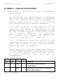
Unique Micro Design
Advanced Thinking Products
Model 164 Quad Coupler
User Manual
Document reference : DOC-M164-UM
UMD Part Number : 6-0164-993-4
Issue 1 - First release
Revision 2/12/92
Unique Micro Design
DOC-M164-UM
Unique Micro Design
Advanced Thinking Products
Model 164 Quad Coupler
Document reference : DOC-M164-UM
UMD Part Number : 6-0164-993-4
Issue 1 - First release
Revision 2/12/92
Unique Micro Design Pty Ltd
(A.C.N. 007 419 490)
2 / 23 Wadhurst Drive
Boronia Vic 3155
Australia
Tel +61-3-887-1022
Fax +61-3-887-0734
Copyright (C) 1992 Unique Micro Design P/L
Issue 1
2/12/92
2
Unique Micro Design
Issue 1
DOC-M164-UM
Issue
Date
Comments
1
2/12/92
First release
2/12/92
3
Unique Micro Design
DOC-M164-UM
1. Introduction
1.1 Scope
This
manual
provides
installation
and
configuration details for the
Unique Micro
Design Model 164 Quad Coupler.
1.2 Overview
The Model 164 Quad Coupler is a general
purpose microcomputer based device which
provides three full duplex serial ports and
a configurable parallel I/O port. Its
multiple operating modes are selected by a
series of switches.
This
manual
describes
the
Model
164
operating with the standard firmware. Other
firmware options can be provided to suit
specific applications.
Issue 1
2/12/92
4
Unique Micro Design
DOC-M164-UM
1.3 Description
S3
D
E
S1
Quad Coupler
Advanced Thinking Products
+DC
GND
A
B
C
PARALLEL I/O
Model 164
S2
Power
Status
The three serial ports on the Model 164 are
designated S1, S2 and S3. A parallel port is
also provided which can be configured either
as an input, designated PI, or configured as
an output, designated PO.
The Model 164 can operate in a number of
modes as configured via the externally
accessible switches. These switches are
arranged in five banks designated "A" to "E"
with each bank comprising four switches,
numbered 1 to 4. For example, switch 2 of
bank "B" is designated "B-2".
Issue 1
2/12/92
5
Unique Micro Design
DOC-M164-UM
There are two indicators - power and status.
The power indicator lights when power is
applied to the unit. The status indicator
flashes once on successful power up and
flashes in various sequences to indicate
error and other conditions.
Issue 1
2/12/92
6
Unique Micro Design
DOC-M164-UM
1.4 Modes of operation
The Model 164 is a multi-functional device.
It can operate as a:
* serial to parallel converter
* parallel to serial converter
* ASCII to PC TERM
converter
* simple baud rate converter
* serial wedge
* printer sharer
* code activated switch
There are four basic operating modes with
the Model 164, numbered from 1 to 4. These
modes determine how the parallel I/O and
serial
ports
behave.
These
modes
are
selected by switches C-1 and C-2 which are
detailed
in
chapter
2.
The
following
sections
describe
some
typical
configurations.
1.5 Parallel to serial converter
Mode 1 has the parallel port configured as
an input (ie it connects to the printer port
of a PC). Input into this port is output to
S1, thereby converting parallel input to
serial output.
Issue 1
2/12/92
7
Unique Micro Design
DOC-M164-UM
Optional
PC Term
Conversion
Parallel
Port
Serial Port
S1
Serial Port
S2
Serial Port
S3
1.6 Serial wedge
1
also
offers
a
serial
wedging
function. Here, S1 and S2 can communicate
bidirectionally. Serial port S3 inserts its
input into this stream by either outputting
to S1 (ie where communication is full duplex
with the terminal) or both S1 or S2 (where
communication is half duplex). In this way a
bar code scanner can insert its data between
a terminal and a host computer.
Mode
Issue 1
2/12/92
8
Unique Micro Design
DOC-M164-UM
Parallel
Port
Optional
PC Term
Conversion
Serial Port
S1
Serial Port
S2
Serial Port
S3
Scanner
1.7 PC TERM conversion
In mode 1, ASCII input to S3 can optionally
be converted to PC TERM output, allowing bar
code scanners and the like to be inserted in
between terminals running PC TERM and the
multi-user system.
1.8 Serial to Parallel converter
With mode 2 the parallel port is configured
as an output (ie it connects to a parallel
printer). This mode provides serial input
conversion to parallel output.
Issue 1
2/12/92
9
Unique Micro Design
DOC-M164-UM
Parallel
Port
Optional
PC Term
Conversion
Serial Port
S1
Serial Port
S2
Serial Port
S3
As Mode 2 has input from serial port S2
directed to S1, a host computer could
communicate with a parallel printer whilst
receiving input from a bar code scanner.
Issue 1
2/12/92
10
Unique Micro Design
DOC-M164-UM
1.9 Code activated switch
3
provides
code
activated
switch
functionality
where
parallel
input
is
interpreted for codes which direct output to
a selected serial port.
Mode
Parallel
Port
Serial Port
S1
Serial Port
S2
Serial Port
S3
1.10 Printer sharer
4
provides
printer
sharing
functionality. Here input to S1, S2 and S3
is directed to the parallel output port.
Port contention is resolved by time out, ie
if say, S1 is outputting to the printer then
S2 is locked out from sending information
until S1 finishes its job. Job completion is
determined by having no activity for a
selected time out period.
Mode
Issue 1
2/12/92
11
Unique Micro Design
DOC-M164-UM
Parallel
Port
Serial Port
S1
Issue 1
2/12/92
Serial Port
S2
Serial Port
S3
12
Unique Micro Design
DOC-M164-UM
2. Configuration
2.1 Mode 1 - Serial Wedge/Parallel to Serial Converter
With mode 1, the parallel port is configured
as an input with its data being directed to
S1 providing parallel to serial conversion.
Mode 1 also provides serial wedging. Here S1
and S2 are cross-linked which provides Host
to Terminal communications. S3 is wedged
between S1 and S2, allowing scanner (or
other) input into the data stream. Optional
PC TERM conversion may be enabled on S3
input to allow ASCII devices to communicate
with PC TERM Host systems.
C-1 C-2
OFF OFF
C-3
C-4
OFF
OFF
ON
ON
OFF
ON
Issue 1
2/12/92
Mode 1
S3 no conversion
S3 to S1 (full duplex)
S3 to S1 & S2 (half duplex)
S3 PC Term conversion
(S3 to S1)
No intercharacter delay
Intercharacter delay of 30 mS
13
Unique Micro Design
DOC-M164-UM
2.1.1 PC TERM conversion handshake
When PC TERM conversion is invoked, software
handshake (when enabled) will use the PC
TERM protocol. Hardware handshaking operates
as normal. The Host (running PC TERM) must
be connected to S1 and the terminal to S2.
The software handshake only operates for
data travelling from S1 to S2, ie there is
no terminal/scanner to Host software flow
control. For this reason, switch C-4 enables
an intercharacter delay to slow down data
input from S3 if needed.
2.1.2 S3 blocking in modes 1 & 2
In modes 1 and 2, input received on serial
channel S3 may be blocked.
Here input is
buffered
until a terminator character is
received, which in the standard firmware
option is the carriage return control
character (ie hexadecimal 0D, decimal 13).
Once the terminating character is received,
the optional
preamble character string is
output followed by the buffered characters
(excluding
the
terminating
character)
followed by the optional postamble character
string.
The received block may be manipulated as
determined by the block modifier routine
given in the table below. A Spectra-Physics
bar code symbology id stripping modifier is
provided as standard, other routines can be
provide upon request.
Issue 1
2/12/92
14
Unique Micro Design
DOC-M164-UM
Input from Spectra
Physics Scanner
FF12234567890<CR>
<STX>1234567890<ETX>
Output
Example of block modifer 2 with <STX> preamble and <ETX>
postamble
Block
modifier
routine
1
2
Description
No manipulation
Spectra-Physics bar code symbology id
characters removed
reserved
3
Block modifier routines
Switch
Setting
A-3
A-4
OFF
OFF
ON
OFF
OFF
ON
ON
ON
A-1
OFF
ON
OFF
A-2
OFF
OFF
ON
Issue 1
2/12/92
Blocking type
none
[preamble] [modified BLOCK using routine
1] [postamble]
[preamble] [modified BLOCK using routine
2] [postamble]
[preamble] [modified BLOCK using routine
3] [postamble]
Description
Reserved
Reserved
Reserved
15
Unique Micro Design
ON
ON
DOC-M164-UM
Reserved
Switch bank A in Modes 1 & 2
Blocking selection
2.1.3 Pre- and post-amble strings
Switch bank B is used to select the pre- and
post-amble character strings which are sent
with blocked data in modes 1 and 2.
Switch
Setting
B-1
OFF
ON
OFF
ON
B-3
OFF
ON
OFF
ON
where
Preamble (valid when blocking enabled)
B-2
OFF
OFF
ON
ON
none
<STX>
reserved
reserved
B-4
Postamble (valid when blocking enabled)
OFF none
OFF <ETX>
ON
<CR>
ON
<CR><LF>
Code
Hexadecimal
Decimal
<STX>
02
2
<ETX>
03
3
<LF>
0A
10
<CR>
0D
13
Switch definitions
Pre/post-amble string selection
Issue 1
2/12/92
16
Unique Micro Design
DOC-M164-UM
2.2 Mode 2 - Serial to Parallel Converter
With mode 2, the parallel port is configured
as an output and accepts input from S1. The
operation of S3 is the same as mode 1.
C-1
ON
C-2
OFF
C-3
OF
F
ON
Issue 1
2/12/92
C-4
Mode 2
S3 no conversion
OFF S3 to S1
ON S3 to S1 & S2
S3 PC Term conversion (S3 to
S1)
OFF No intercharacter delay
ON Intercharacter delay of 30 mS
17
Unique Micro Design
DOC-M164-UM
2.3 Mode 3 - Code Activated Switch
With mode 3, the parallel port is configured
as an input.
In this mode, the Quad Coupler is operating
as a code activated switch. Input is accepted
from the parallel port and is directed to
either serial port S1, S2 or S3 as selected
by a designated two character sequence.
The first character in the sequence is the
selection code which is determined by the
binary pattern given in switch banks A and
B. The second character determines which
port to select: ASCII "1" (ie hexadecimal
31, decimal 49) selects S1, ASCII "2"
selects S2 and ASCII "3" selects S3.
If it is desired to send the selection code
character through to the selected output
port, two of these selection code characters
need to be sent in sequence.
With switch C-3 on, the selection code is
only interpreted after a selected idle time.
In this way, graphic data which may contain
a
valid
selection
code
will
not
be
interpreted.
C-1 C-2
OFF ON
C-3
OFF
ON
Issue 1
2/12/92
C-4
Mode 3
Selection code always
interpreted
Selection code only interpreted
after idle timeout
18
Unique Micro Design
DOC-M164-UM
OFF 30 second idle timeout
ON 10 second idle timeout
OFF = 1 bit, ON = 0 bit
A-1 A-2
A-3 A-4
bit 7 bit 6 bit 5 bit 4
B-1
bit 3
B-2
bit 2
B-3
bit 1
B-4
bit 0
Switch bank A and B in Mode 3
Selection code character
2.4 Mode 4 - Printer Sharer
With mode 4, the parallel port is configured
as an output.
In this mode the Quad Coupler is operating as
a printer sharer. Here the parallel output
port is shared between the three serial
input ports. Contention is resolved on a
first come, first served basis with the
first active serial port being assigned to
the printer port. After no activity on the
active input port for the selected idle
timeout
period,
the
parallel
port
is
released for allocation to the next active
serial port.
Switch C-3 selects whether a form feed
control character is sent after a print job.
C-1
ON
C-2
ON
C-3
OFF
Issue 1
2/12/92
C-4
Mode 4
No form feed sent after idle
timeout
19
Unique Micro Design
ON
Issue 1
2/12/92
DOC-M164-UM
Form feed sent after idle timeout
OFF 30 second idle timeout
ON 10 second idle timeout
20
Unique Micro Design
DOC-M164-UM
2.5 Communications parameters
For
serial
channel
S3,
the
serial
communications parameters are fixed at 9600
baud, 8 data bits with no parity and one
stop bit with hardware handshaking. For
serial channels S1 & S2, switch bank D and
E determine their parameters.
Switch setting
D-1
D-2
ON
ON
OFF
OFF
OFF
OFF
OFF
ON
OFF
ON
ON
OFF
ON
ON
ON
OFF
Baud rate
D-3
ON
OFF
ON
OFF
ON
OFF
OFF
ON
38.4K
19.2K
9600
4800
2400
1200
600
300
Switch definitions
Serial ports S1 & S2 baud rate
Switch setting
D-4
OFF
ON
Description
Data bits
8
7
E-1
OFF
ON
Parity
Enabled
Disabled
Issue 1
2/12/92
21
Unique Micro Design
E-2
OFF
ON
Parity type
Even
Odd
E-3
OFF
ON
S1 handshake
Hardware DTR/CTS
Software XON/XOFF
E-4
OFF
ON
S2 handshake
Hardware DTR/CTS
Software XON/XOFF
DOC-M164-UM
Switch definitions
S1 & S2 communications parameters
Issue 1
2/12/92
22
Unique Micro Design
DOC-M164-UM
4. Interfaces
4.1 Serial interfaces
The serial interfaces use +/- 10 Volt
levels. The pin consigment on the DB9 plug
(male) is a subset of the PC/AT
serial
interface.
Pin
1
2
3
4
5
6
7
I/O
i/p
o/p
o/p
o/p
8
9
case
i/p
-
Description
no connection
RxD
TxD
DTR (input data stream handshake)
Ground
no connection
RTS (ie always asserted)
tied to +5V (can power external devices)
CTS (output data stream handshake)
no connection
Ground
Serial interface
DB9 plug connector
*1 * * * *5
*6 * * *9
Front view of DB9 plug
Issue 1
2/12/92
23
Unique Micro Design
DOC-M164-UM
4.2 Parallel Interface
Pin
1
2
3
4
5
6
7
8
9
10
11
12
13
14
15
16
17
18-25
Description
Strobe(-)
Data 0
Data 1
Data 2
Data 3
Data 4
Data 5
Data 6
Data 7
Acknowledge(-)
Busy
Paper end
Select
Autofeed(-)
Error(-)
Initialise(-)
Select input(-)
Ground
As output
O
O
O
O
O
O
O
O
O
I
I
I=GND
I n/c
O n/c
I n/c
O n/c
O n/c
-
As input
I
I
I
I
I
I
I
I
I
O
O
O=GND
O n/c
I n/c
O n/c
I n/c
I n/c
-
Parallel I/O interface
DB25 socket connector
13 * * * * * * * * * * * * * 1
25 * * * * * * * * * * * * 14
Front view of DB25 socket
Issue 1
2/12/92
24
Unique Micro Design
DOC-M164-UM
4.3 External power interface
The Model 164 requires 6 to 9 volts DC at
300 mA to operate. The external power
connector connects to standard plug packs
with centre pin grounded.
Issue 1
2/12/92
25
Unique Micro Design
DOC-M164-UM
4.4 Typical cables
4.4.1 To serial port of Printer
PC serial port
DB25 plug
M164 serial port
DB9 socket
2 --------------------2
3 --------------------3
7 --------------------5
20--------------------8
4.4.2 To serial port of PC
PC serial port
DB25 socket
M164 serial port
DB9 socket
2 --------------------2
3 --------------------3
5 -|
6 --------------------4
7 --------------------5
20--------------------8
Issue 1
2/12/92
26
Unique Micro Design
PC serial port
DB9 socket
DOC-M164-UM
M164 serial port
DB9 socket
2 --------------------3
3 --------------------2
6 -|
8 --------------------4
5 --------------------5
4 --------------------8
|
--6
4.4.3 To Centronics printer
A standard PC parallel printer cable should
be used to connect the parallel port of the
Model 164 to a Centronics printer.
4.4.4 To parallel port of PC
A straight through pin to pin DB25 plug to
DB25 plug cable is used to connect the
parallel port of a PC to the parallel input
port of the Model 164.
Issue 1
2/12/92
27